Distributed Design Series™ High-Fidelity Coaxial Ceiling Loudspeakers Installation and Operation Manual D10 D10SUB Model D4LP D4 D5 D6 & D6-B D8 D10 D10SUB Driver Diameter 4.5" 4.5" 5.0" 6.5" 8.0" 10.0" 10.0" 114.3 mm 114.3 mm 127 mm 165.1 mm 203.2 mm 254.0 mm 254.
Introduction Thank you for selecting the Community Distributed Design Series™ of ceiling loudspeakers. Whether you chose them because they deliver exceptionally high quality sound, because they have predictable, uniform coverage so spaces are easy to lay out, because they are easy to install and save time, or because they are very competitively priced for such a high-performance, durable loudspeaker, you can have confidence you made the right choice.
Table of Contents Important Safety Instructions . . . . . . . . . . . . . . . . . . . . . . . . . . . . . 5 L’information de Sûreté Importante . . . . . . . . . . . . . . . . . . . . . . . . . . 6 Unpacking and Inspection . . . . . . . . . . . . . . . . . . . . . . . . . . . . . . . 7 Option 1: Full Ceiling Loudspeaker Assembly* . . . . . . . . . . . . . . . . . . . . 8 Option 2: Face Only. . . . . .
Table of Figures Figure 1. Full Ceiling Loudspeaker assembly package contents (typical) . . . . . . . . 8 Figure 2. Face Only package contents (typical) . . . . . . . . . . . . . . . . . . . . . 9 Figure 3. Back Can package contents (typical) . . . . . . . . . . . . . . . . . . . . . 10 Figure 4. Optional Accessories. . . . . . . . . . . . . . . . . . . . . . . . . . . . . . . . 11 Figure 5. D45-BC Back can dimensions. . . . . . . . . . . . . . . . . . . .
Important Safety Instructions Always follow these basic safety precautions when using or installing Distributed Design loudspeakers and accessories: • Read these instructions. • Keep these instructions. • Heed all warnings. • Follow all instructions, particularly those pertaining to rigging, mounting, hanging and electrical connections. • Do not use this apparatus near water. • Clean only with dry cloth. • Do not block any ventilation openings. Install in accordance with the manufacturer’s instruction.
L’information de Sûreté Importante PRECAUTION : Veuillez toujours suivrent ces mesures de sécurité de base lors de l’utilisation ou lors de l’installation des haut-parleurs Distributed Design et de ces accessoires: • Lisez et Gardez les instructions. • Observez tous les avertissements. • Suivez toutes les instructions, particulierement ceux concernant le calage, support, montage et raccordements électriques. • Ne pas utiliser cet appareil près de l’eau. • Nettoyez seulement avec un tissu sec.
EC Statement of Conformity This document confirms that the range of products of Community Professional Loudspeakers bearing the CE label meet all of the requirements in the EMC directive 89/336/EEC laid down by the Member States Council for adjustment of legal requirements. Furthermore, the products comply with the rules and regulations referring to the electromagnetic compatibility of devices from 30-August-1995.
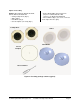
Option 1: Full Ceiling Loudspeaker Assembly* Models: D4LP, D4, D5, D6, D6-B, D8, D10, D10SUB • Ceiling Loudspeaker Assembly (Qty 2) • Back cans (Qty 2) • Tile Support Bridge Rails (Qty 4) • Grilles (Qty 2) Loudspeakers (secured in their back cans) • C-Ring Support Plates (Qty 2) • Cut-out template (can-sized) (Qty 1) • Paint Masks (Qty 2) • Flat screwdriver (Qty 1) (for screws, connectors and to help remove the grille) Grilles C-Ring Support Plates Tile Support Bridge Rails Cut-out Template Paint M
Option 2: Face Only Models: D4-FO, D5-FO, D6-FO, D6-FO-B, D8-FO, D10-FO, D10SUB-FO • Ceiling Loudspeakers (Qty 2) • Grilles (Qty 2) • Paint Masks (Qty 2) • Cut-out template (can-sized) (Qty 1) • 4mm x 20mm Phillips Pan Head Screws (x8 pieces for D4LP, D4, D5 or D6; x16 pieces for D8, D10 and D10SUB) • Flat screwdriver (Qty 1) (for screws, connector and to help remove the grille) Loudspeakers Grilles Paint Masks Cut-out Template Flat screwdriver Figure 2.
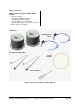
Option 3: Back Can (Models: D4LP-BC, D45-BC, D6-BC, D8-BC, D10-BC) • Back cans (Qty 2) • Tile Support Bridge Rails (Qty 4) • C-Ring Support Plates (Qty 2) • Cut-out template (can-sized) (Qty 1) • Flat screwdriver (Qty 1) (for screws, connectors and to help remove the grille) Back Cans C-Ring Support Plates Tile Support Bridge Rails Cut-out Template Flat screwdriver Figure 3.
Optional Accessories Community offers helpful optional accessories that are not included with the basic packages. Please be sure to order these parts separately if you need them. Retrofit rings are available in two types for various loudspeaker group sizes. The Face Adapter Ring allows you to place the Distributed Design loudspeaker alone in a non-Community made back can.
Specifications Description Ceiling Loudspeaker Type Model 4.5" Low Profile Full Range Coax D4LP 60 Watts 4.5" Standard Full Range Coax D4 100 Watts 5.0" Standard Full Range Coax D5 100 Watts 6.5" Standard Full Range Coax D6, D6-B 150 Watts 8.0" Standard Full Range Coax D8 200 Watts 10.0" Standard Full Range Coax D10 200 Watts 10.0" Subwoofer Subwoofer D10SUB 40 V (200 W) 60 Watts 40 V (200 W) 180° conical 8 ohms 30.98 V (120W) 110° conical N/A 8 ohms 30.
Safety Agency Compliance 4001450 Conforms to UL1480 Standard Conforms to UL2043 Standard Certified to CSA C22.2 No. 60065 Standard For protection against electrical shock and to meet the requirements of the UL2043 standard, the speaker assembly must be installed in the appropriate Listed Community Distributed Design Series Back Box or similar UL1480/UL2043 Listed enclosure.
Figure 5. D45-BC Back can dimensions Figure 7. D4LP-BC Back can dimensions Ø7.142" (181.4) Ø7.189" (182.6) 3.552" (90.2) 6.622" (168.2) 3.421" (86.9) 6.492" (164.9) Ø8.303" (210.9) Ø9.384" (238.3) Ø8.249" (209.5) Ø9.322" (236.8) Figure 6. D4-FO Loudspeaker dimensions Note: The same D4-FO Loudspeaker face assembly is used for the D4 and D4LP as these models differ only with respect to their back cans. 3.293" (83.7) .442" (11.2) Ø8.386" (213) Ø9.768" (248.
Figure 8. D5-FO Loudspeaker dimensions Figure 9. D6-BC Back can dimensions Ø8.858" (225) 6.651" (168.9) 6.520" (165.6) 4.934" (125.3) Ø9.742" (247.4) .442" (11.2) Ø8.386" (213) Ø10.797" (274.2) Ø9.768" (248.1) Note: The D5-FO uses the same D45-BC back can as the D4-FO. Figure 10. D6-FO Loudspeaker dimensions 4.677" (118.8) .462" (11.7) Ø9.881" (251) Ø11.24" (285.
Figure 11. D8-BC Back can dimensions Figure 13. D10-BC Back can dimensions Ø12.431" (315.7) Ø10.592" (269) 8.027" (203.9) 7.896" (200.6) 9.693" (246.2) Ø11.709" (297.4) 9.563" (242.9) Ø13.54" (343.9) Ø12.769" (324.3) Ø14.611" (371.1) Figure 12. D8-FO Loudspeaker dimensions Figure 14. D10-FO Loudspeaker dimensions 7.157" (181.8) 6.067" (154.1) .473" (12) .523" (13.3) Ø11.85" (301) Ø13.209" (335.5) Community Distributed Design Series Ø13.819" (351) Ø15.
Figure 15. D10SUB-FO Loudspeaker dimensions Figure 16. Face adapter ring detail 7.886" (200.3) .523" (13.3) Ø13.819" (351) Ø15.197" (386) Figure 17. Can adapter / trim ring detail Note: The D10SUB-FO loudspeaker uses the same D10-BC back can as the D10-FO loudspeaker.
Component Identification Combination terminal block cover and cable strain relief clamp Input terminal block Knockout strain relief on terminal block cover (with conduit installed) 3/4" and 1" knockout strain relief Zinc plated steel can-locking clamp (4) Drop-Stop™ tab (4) Steel can-locking clamp (shown deployed) Internal leads and plug to bring rear terminal block signal to the loudspeaker’s input connector on the circuit board Twist-Assist™ can mating clip (4) Bass reflex port Hole for 4mm sheet m
Bridge rail clip on C-ring support plate Seismic safety tabs Drop-Stop™ installation assistant tabs Steel can-locking clamp (shown retracted) Tile support bridge rails Stabilizing flange on rail (faces the loudspeaker) Low impedance / 70V & 100V transformer tap switch Grille (shown snapped onto loudspeaker face) Metal safety clip and high-impact mono filament nylon loops that secure grille to loudspeaker face Mounting screw holes on optional face adapter ring (left) and optional can adapter/trim ring (
Wiring Note: This section describes the wiring connection of the loudspeaker to the can, and the wiring between the can and loudspeaker. Installation order will depend upon the facility and the installer; pre-installation of the cans including routing the wires to the can location, or cans and loudspeakers at the same time. There is no "perfect or preferred" order for installation. This section describes the general means to wire the cans and loudspeakers before mounting the can into the ceiling (or wall).
Note: All electrical installation connections for loudspeaker lines are subject to all applicable governmental building and fire codes. The selection of appropriate electrical hardware to interface with the Distributed Design Series loudspeaker lies solely with the installation professional. Community recommends that an appropriately licensed engineer, electrician, or other professional identify and select the appropriate conduit, fittings, wire, etc. for the installation.
Installation of conduit to the back can • Additionally, the top cover has a 3/4" (19 mm) knock-out. Required tools: • One hammer and knockout punch tool • One step-bit for adjusting knockout diameter (optional) • Safety glasses, gloves and other personal safety gear are recommended as this process involves striking metal parts and chipping away debris around the knockouts. 1. All Distributed Design Series loudspeaker back cans have dual-diameter knockout strain relief fittings on each side.
Installing the Back Can in the Ceiling General Lay out the loudspeaker locations according to the requirements of the specific installation and in compliance with applicable safety and building codes. It is beyond the scope of this manual to provide guidance in this area. Community does, however, offer our Forecaster ceiling system software to assist you in distributed loudspeaker system design. Please visit the Product Selection area of Community website for this software.
4. Slide the back can into the hole, aligning it so that its input terminal block OR its knockout strain relief locations are consistent with the wiring distribution you have mapped out. When you press the can fully into place, the four spring-loaded Drop-Stop™ tabs will spread atop the C-ring, and you may hear them "snap" into position; you can now continue without having to hold the can in place. See Figure 26. Figure 26.
Dry-Wall Ceiling Installation There are four basic ways to install a Community Distributed Series loudspeaker assembly into a drywall ceiling (a.k.a. sheet rock or gypsum board). Some are for new construction, others for retrofit to existing construction. We recommend some methods over others and of course the choice is yours. A. The preferred method for new installations is to use the optional New Construction Bracket, pre-installing it directly to the supporting beams before the sheet rock is applied.
Details for Pre-Installation in a New Drywall Ceiling Inserting the Loudspeaker Assembly into the Back Can Optional New Construction Brackets are available for installing loudspeakers in new construction before drywall or plaster is put in place. See Figure 29, and refer to the chart on page 11 for sizes and model numbers. 1. Bring the wiring from the ceiling to the top of the can and attach it to the terminal block (see the next Section of this manual for details).
Painting the Loudspeaker The loudspeakers’ textured white finish complements most decors and does not require further painting. However, if the interior design requires a custom loudspeaker finish, these loudspeakers are easy to paint. It’s best to paint the baffle before installation. In cases where it needs to be finished along with the ceiling, the loudspeaker baffle can be painted after mounting in the ceiling.
Secure the Loudspeaker In the Back Can When you have made the electrical connections from the wires coming into the can to the loudspeaker then you can mount that loudspeaker into the can. 2. Twist the loudspeaker clockwise a few degrees so the Twist-Assist™ face tabs are positioned at the left of the face slots as you look at the front face (see Figures 30 and 31). 1. Four Twist-Assist™ face tabs protrude just inside the can opening.
4. Once the loudspeaker is secured in the back can, you can attach the safety cable between the grille and loudspeaker. There is a nylon mono filament loop attached to the grille and looped through a metal clip. Another mono filament line is located inside the bass reflex port of the face of the loudspeaker. Use the metal clip to link these two mono filament loops. See Figure 33. 5. Carefully lower the grille until the cable holds it, and let go. It should hang harmlessly from the mono filament line. 6.
Loudspeaker Tap Setting You can use a standard #2 or #3 Phillips or a medium slot-blade screwdriver such (not the one provided with the loudspeaker kit), or just press with your thumb firmly, and twist to adjust the power control dial on the front face of the loudspeaker baffle. As shown in Figure 34, you can make any of five different settings, although the dial has dual calibrations so at first glance it appears to have ten settings.
Warranty Information and Service TRANSFERABLE WARRANTY "(LIMITED)" - VALID IN THE USA ONLY NOTES The Distributed Design Ceiling Loudspeaker Systems are designed and backed by Community Professional Loudspeakers. For complete warranty information within the USA please refer to the Warranty Card enclosed with the product, or the website: www.communitypro.com/warranty. Please call 610-876-3400 to locate your nearest Authorized Field Service Station. For Factory Service call 610-876-3400.
Community Professional Loudspeakers 333 East Fifth Street, Chester, PA 19013-4511 USA Tel: (610) 876-3400 • Fax: (610)874-0190 communitypro.