
Specifications


Community Distributed Design Series Installation and Operation Manual Page 24
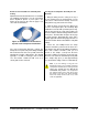
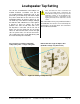
4. Slide the back can into the hole, aligning it
so that its input terminal block OR its knockout
strain relief locations are consistent with the
wiring distribution you have mapped out. When
you press the can fully into place, the four
spring-loaded Drop-Stop™ tabs will spread
atop the C-ring, and you may hear them "snap"
into position; you can now continue without
having to hold the can in place. See Figure 26.
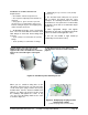
Figure 26. Drop-Stop™ tabs (highlighted)
snap out over C-Ring support
(Temporarily holds can in place even before you secure
it with the steel mounting clamps)
Rotate the back can as necessary to ensure all of
the clamps are oriented to contact and compress
the C-Ringtothe ceiling tileduringstepve as
follows.
Note: If you’re using loose wires, rather than conduit, it
makes sense to rst connect the wires to the terminal
block atop the can, and secure them with the top cover/
strain relief, before installing the can through the cutout
and into place in the C-Ring.
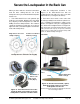
5. Locate the four Phillips-head can clamp
actuators around the perimeter of the back can’s
front ange (seeFigure27).Usinga #2 Phillips
screwdriver twist each actuator clockwise until
you feel resistance as the can clamp presses
against the ceiling.
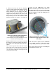
Figure 27. Turning the can clamp actuators
clockwise securely locks the back can into
the ceiling.
6. This concludes a single back can installation
for a standard suspended ceiling. Repeat for
as many loudspeakers as you need to install.
Refer to page 28 for instructions on installing the
loudspeaker into the back can.