R SERIES Loudspeakers With Unparalleled Musicality, Superior Voice Projection and Premium Weather Resistance Installation and Operation Manual Models: R.
IMPORTANT SAFETY INSTRUCTIONS RIGGING AND ELECTRICAL SAFETY Always follow these basic safety precautions when using or installing R SERIES loudspeakers and accessories: DANGER: The loudspeakers described in this manual are designed and intended to be ‘flown’ or suspended using a variety of rigging hardware, means, and methods. Installation of loudspeakers should only be performed by trained and qualified personnel.
UNPACKING AND INSPECTION SYSTEM INFORMATION Community R SERIES loudspeakers are engineered and manufactured to be rugged and they are carefully packed in sturdy cartons. Make sure that the number of cartons shown on the freight documents have actually been delivered. It is wise to thoroughly inspect each unit after it has been removed from the packaging, as damage could occur during shipping.
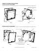
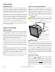
PRODUCT FEATURES IDENTIFICATION TYPICAL R.5-MAX FULL-RANGE MODEL Safety Cable Attachment Point: (Utilize empty rigging point. User must supply appropriate fastener and safety cable) Installer to supply hardware for top attachment of strap to yoke Yoke Aiming Strap Grille 3/8"-16 Rigging points (sides and back) 5 Rigging Points (3/8"-16) (sides + back) FRONT Gland Nut / Cable REAR TYPICAL R2-MAX FULL-RANGE MODEL Safety Cable Attachment Point: (Utilize empty rigging point.
RIGGING / SUSPENSION AND SAFETY TERMINOLOGY: The terms “rigging", “flying" and “suspension" are often used interchangeably to describe the installation of loudspeaker systems above ground level. None of these terms pertain to, or attempt to describe, the actual method that is used (cables, brackets, chains, etc.). DANGER: The loudspeakers described in this manual are designed and intended to be suspended using a variety of rigging hardware, means, and methods.
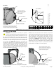
INSTALLATION BEFORE YOU START MOUNT THE R.5-MAX LOUDSPEAKER q Read all instructions and gather tools necessary before starting the installation. Please read all safety instructions and warnings regarding rigging and installation of the loudspeaker. The "q" preceding each step can be used to check off each step as it is completed (or applicable). q Attach the R.5-MAX loudspeaker to the yoke. See Figure 2. The mounting point holes are approximately 7/16" (11mm) deep.
R.5-MAX Yoke 0° Securing Strap X° Angle Securing Strap (determine approximate hole to use based on chart at right) 11 10 9 8 7 6 5 4 3 2 1 3/8" SS Flat Washer 3/8" SS Hex Nut 3/8" SS Lock Washer 3/8"-16 x 1-1/4" SS Stud (leave 3/4" sticking out) Hardware to secure the strap to the yoke appropriate for yoke attachment to the structure must be supplied by the installer Hole # 1 2 Down Angle 3° 6° 3 4 5 6 7 8 9 10 11 14° 18° 20° 25° 29.5° 36° 41.5° 47° 50° Figure 3.
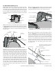
R2-MAX INSTALLATION (cont'd) q Mount the R2-MAX and yoke to the support structure. If the center hole is being used to mount the yoke, that hardware must be installed before attaching the securing strap to the yoke. All mounting hardware must be supplied by the installer and be weather-resistant and properly rated for the weight and potential wind load by a structural engineer. q Attach the free end of the contour strap to the enclosure as shown in Figure 5b.
WIRING AND ELECTRICAL SAFETY All standard R-MAX loudspeakers come with attached SJOW rated input cables, 12' (3.6m) in length. The cable enters the enclosure through a waterproof gland nut. The other end of the cable is un-terminated. Beyond this length, line-loss calculations should be performed when selecting additional wiring to prevent losses in output due to voltage drops resulting from increased impedance.
MAINTAINING WEATHER RESISTANCE SERVICE AND SUPPORT GUIDELINES FOR R SERIES OUTDOOR USE INFORMATION AND APPLICATION ASSISTANCE R SERIES is suitable for outdoor direct exposure installation when used as recommended. For best results in outdoor applications, follow these guidelines: For more information on installing and operating your R SERIES loudspeaker, please refer to Community’s web site at communitypro.com.
SPECIFICATIONS R.5-66 MAX R.5-96 MAX Loudspeaker Type: 2 way, full-range, coaxial 2 way, full-range, coaxial Driver Complement: LF: 1 x 12" with neodymium motor and aluminum demodulation ring HF: 1 x 1.4" exit compression driver with 2.87" voice coil LF: 1 x 12" with neodymium motor and aluminum demodulation ring HF: 1 x 1.4" exit compression driver with 2.
SPECIFICATIONS R2-64 MAX R2-66 MAX R2-94 MAX SYSTEM TRANSDUCERS LF: MF: HF: 2 x 12" inherently weather-resistant cones with 3" voice coil, neodymium motor and aluminum demodulation ring 1 x 2" exit, M200HP compression, 3.5" diaphragm, 2.2" Voice coil, high temp non-metallic diaphragm 1 x 1.4" exit compression, 2.
R-MAX SPEC SHEET PROCESSING DETAILS COMMUNITY LOUDSPEAKER DATA: “TRUE TO SPECIFICATION” Ever since Community pioneered the measurement and publication of detailed loudspeaker specifications in 1976, we have striven to present the most relevant, useful, and technically correct loudspeaker data to our customers.
LOW FREQUENCY “BOOST” EFFECT (continued) Now, as a thought experiment, imagine that we apply the specified maximum of 63 Volts to the entire loudspeaker before applying the recommended +6 dB boost at 70 Hz. The entire bandwidth of the loudspeaker would then be operating at its 2000 watt limit. Now, add the +6 dB boost at 70 Hz into the signal chain.
COMMUNITY'S ALTERNATE APPROACH (continued) In the spirit of our efforts to offer “full-disclosure” specifications and DSP settings, we limited the R-MAX LF boost to no more than 6 dB. Figures 11 and 12 show a comparison of the R2-64MAX with and without the 6 dB LF EQ boost, and the EQ transfer function for each.
COMMUNITY'S ALTERNATE APPROACH (continued) Both R.5-MAX products also use 6dB of LF boost to create the “Processed” Frequency Response graphs shown on the spec sheets. Figure 13 shows the response curves, with notation, for the R.5-66MAX and Figure 14 shows the R.
TECHNICAL DRAWINGS TYPICAL R.5-MAX COAXIAL LOUDSPEAKER 8" (203mm) 16" (406mm) (5) 3/8"-16 Threaded Inserts .2" (5mm) 10.2" (259mm) typ Center of Gravity 9" (229mm) 9" (229mm) 16.39" (416mm) Ø 0.45" (Ø 12mm) hole x 4 Center Line Top 8.2" (208mm) Ø 0.55" (Ø 14mm) Center only 2" (51mm) 1" (25mm) 4.63" (117mm) 2.75" (70mm) 4.63" (117mm) 2.75" (70mm) NOTE: YOKE MOUNT AND MEASURMENTS NOTE: YOKE MOUNT A .125" [3MM] TOLER AND MEASURMENTS A .125" [3MM] TOLER Yoke Dimensions 16.
TECHNICAL DRAWINGS TYPICAL R2-MAX COAXIAL LOUDSPEAKER 13.5" (343mm) 8" (203mm) 8" (203mm) Center of Gravity Ø .53" (Ø 13.5mm) typ. Top 30.75" (781mm) Yoke 24.75" (629mm) 17.25" (438mm) 12.38" (314mm) 15.43" (392mm) 12.38" (314mm) 24.75" (629mm) Center of Gravity Rear Page 18 (5) 1/2"-13 Threaded Inserts Sides Installation and Operation Manual Center of Gravity Front R.
ACCESSORIES (for R.5-MAX only) Pole mount bracket kit for mounting a single R.25, R.5, RMG-200A, W2-218, W2-228, W2-2W8 or W2-2V8 loudspeaker. Vertical downtilt to 90°. PMB-1RR Pole mount bracket kit for mounting one (1) R.25, R.5, RMG-200A, W2-218, W2-228, W2-2W8 or W2-2V8 loudspeaker, or two (2) loudspeakers in a "top-bottom" configuration, with left-to-right panning capability and vertical downtilt.
R SERIES ©2014 Community Professional Loudspeakers Community Professional Loudspeakers 333 East Fifth Street, Chester, PA 19013-4511 USA Phone: Page 20(610) 876-3400 • Fax: (610) 874-0190 www.communitypro.com Installation and Operation Manual Part#: 112928 v:9OCT2014 R.