R SERIES INSTALLATION / OPERATION MANUAL
EC STATEMENT OF CONFORMITY E C S TAT E M E N T O F C O N F O R M I T Y This document confirms that the range of products of Community Professional Loudspeakers bearing the CE label meets all of the requirements in the EMC directive 89/336/EEC laid down by the Member States Council for adjustment of legal requirements. Furthermore, the products comply with the rules and regulations referring to the electromagnetic compatibility of devices from 30-August-1995.
WELCOME TO COMMUNITY A T R A D I T I O N O F E X C E L L E N C E A N D I N N O VAT I O N Since the founding of our company in 1968, Community has been a constant developer and innovator of loudspeaker technology. Many of our engineering achievements were undertaken to solve problems, when no prior solutions existed. Others resulted from simply seeing a better way to do things.
TABLE OF CONTENTS CONTENTS EC Statement of Conformity ........................................................................................................ Page 2 Welcome to Community ................................................................................................................ Page 3 Important Safety Information ....................................................................................................... Page 6 Rigging and Electrical Safety ...................................
TABLE OF FIGURES AND DRAWINGS F I G U R E S A N D D R AW I N G S Figure 1: Recommended Cable Gauge ............................................................................ Page 19 Figure 2: Protection Capacitor Equation ........................................................................... Page 20 Figure 3: 70-Volt Impedance Equation ............................................................................. Page 20 Figure 4: Mounting Point Detail..................................................
IMPORTANT SAFETY INFORMATION I M P O R TA N T S A F E T Y I N F O R M AT I O N Always follow these basic safety precautions when using or installing R SERIES loudspeakers and accessories: Read these instructions. Keep these instructions. Heed all warnings. Follow all instructions, particularly those pertaining to rigging, mounting, hanging and electrical connections. Only use accessories that are specified and approved by the manufacturer.
UNPACKING AND INSPECTION U N PA C K I N G A N D I N S P E C T I O N R SERIES loudspeakers are inherently rugged and are carefully packed in sturdy cartons. However, it’s wise to thoroughly inspect each unit after it has been removed from the packaging, as damage could occur during shipping. SHIPPING CLAIMS Please note that once the shipment has left your dealer or the Community factory, the responsibility for damage is always borne by the freight company.
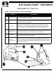
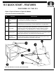
R.25 QUICK START - FEATURES F E AT U R E S O F T H E R . 2 5 Figure 1: Physical Features of Typical R.25 Models NO. FEATURE DESCRIPTION 1 Mounting/Rigging Points Five integral M8 (8mm) threaded mounting points on the sides and the back of the R.25 mate with the yoke bracket. 2 Grille 22-gauge perforated stainless steel grille backed by a foam sheet and stainless steel mesh (100 x 100 wires/sq in). 3 Input Cable Attached 16 Gauge SJOW cable, approximately 12 feet (4m) long, rated for outdoor use.
R.5 QUICK START - FEATURES F E AT U R E S O F T H E R . 5 Figure 2: Physical Features of Typical R.5 Models (R.5Z, R.5HP, R.5COAX and R.5SUB models) NO. FEATURE DESCRIPTION 1 Mounting/Rigging Points Five integral 3/8-16 threaded mounting points on the sides and the back of the R.5 mate with the yoke bracket or aiming strap. 2 Grille 20-gauge perforated stainless steel grille backed by a foam sheet and stainless steel mesh (100 x 100 wires/sq in). (R.
QUICK START - INSTALLATION E L E C T R I C A L I N S TA L L AT I O N A N D S A F E T Y Electrical Safety The output voltage and current capabilities of audio power amplifiers present a danger to installers especially in 70-volt and 100-volt distributed systems. To minimize the risk of electric shock from loudspeaker connecting cables, confirm that the power amplifiers are turned “off” before connecting loudspeaker cable to the loudspeaker or amplifier.
QUICK START - INSTALLATION M E C H A N I C A L I N S TA L L AT I O N A N D S A F E T Y Rigging Safety The loudspeakers described in this manual are designed and intended to be ‘flown’ or suspended for maximum acoustical performance using a variety of rigging hardware, means, and methods. It is essential that all installation work involving the suspension of these loudspeaker products be performed by competent, knowledgeable persons who understand safe rigging practices.
INTRODUCTION INTRODUCTION Community’s R SERIES is a high-quality, high-fidelity product line designed to be highly weather-resistant. R SERIES products perform consistently in continuous outdoor exposure while simultaneously providing superlative acoustic performance. This manual is intended to help you install and use R SERIES loudspeakers safely and effectively. It provides useful information to help you obtain the best performance, sound quality, and reliability from your R SERIES systems.
APPLICATIONS R SERIES Applications R SERIES products are designed for permanent installation or portable use both outdoors and indoors. The primary applications for Community’s R SERIES are those where re-entrant horns, outdoor two-way horn/woofer loudspeakers, and some larger horn loudspeakers typically are used but lack capability for both high quality music reproduction and longer distance voice projection.
FEATURES R S E R I E S F E AT U R E S R SERIES products are entirely constructed of corrosion-resistant materials like fiberglass, stainless steel, polyimide and carbon fiber, using sophisticated technologies to ensure they will withstand exposure to harsh environmental conditions. Weather-Treated Cones Community applies a special weather treatment to the low-frequency cones used in R SERIES products to maximize their long-term resistance to temperature, moisture and dry-rot problems.
FEATURES Weather-Stop™ Grille Each enclosure is fitted with Community’s proprietary Weather-Stop™ protective grille. The grille consists of a corrosion-resistant outer layer of perforated steel with a proprietary zinc-rich epoxy dual-layer powder coat finish in light grey, a center layer of UV-resistant reticulated foam, and an inner layer of fine-mesh screen made from a UV-resistant synthetic material that blocks rain and fights rusting.
MODELS R SERIES MODELS The R SERIES family features 22 models that range in capability from short throw usage for local area fill (about 30 to 50 feet), to extremely long throw capable of reaching across an entire stadium (about 700 feet). A wide selection of coverage angles and power output capabilities characterize this versatile product line. A small, single 12” subwoofer (called the R.5SUB) and a much larger dual 12” subwoofer (called the R2SUB) are available to complement full-range systems.
MODELS R.5HP High-Performance, Medium-Throw 12-Inch Full-Range The “high performance” R.5HP is a three-way horn loaded system engineered to provide maximum intelligibility from the same compact form factor. By combining Community's M200 midrange driver coaxially within the mouth of a 12" LF horn, an extremely powerful tool for voice announcement systems with 60 x 40 degree coverage was created. High frequencies are handled by Community's non-metallic diaphragm UC1 1" exit HF driver.
INSTALLATION E L E C T R I C A L I N S TA L L AT I O N A N D S A F E T Y DANGER: The output voltage and current of audio power amplifiers are a shock hazard especially in 70-volt and 100-volt distributed systems. To minimize the risk of electric shock from loudspeaker connecting cables, confirm that the power amplifiers are turned “off” before connecting loudspeaker cable to the loudspeaker or amplifier. Always follow local electrical codes and proper electrical safety procedures.
INSTALLATION However, in most cases, using transformer versions of the R SERIES loudspeakers along with 70.7 volt or 100 volt amplification will yield the best performance at a reasonable cost. In this approach, the need for larger gauge wire will be reduced. Refer to pages 10 and 21 for more discussion of this topic and the technical support page of our website for technical articles on this subject.
INSTALLATION Use of Limiters Community recommends use of a limiter to help prevent loudspeaker damage due to sudden transients (dropped microphones, etc.) or amplifier clipping. When used for this purpose, connect the limiter as the last item in the signal chain before the power amplifier (at the input to the power amplifier). Set the limiter’s “threshold” high enough so that no limiting occurs until the signal is in danger of clipping.
INSTALLATION Loudspeaker Grounding In a low-impedance (8-ohm) system (not 70/100-volt), the minus (-) output terminal of the power amplifier is usually grounded. This provides a ground reference for the loudspeaker. In a 70/100-volt system, it is necessary for the amplifier output terminals to be ungrounded. Thus, there is no ground reference for the loudspeaker. In most cases, this is acceptable.
INSTALLATION M E C H A N I C A L I N S TA L L AT I O N A N D S A F E T Y DANGER: The loudspeakers described in this manual are designed and intended to be ‘flown’ or suspended for maximum acoustical performance using a variety of rigging hardware, means, and methods. It is essential that all installation work involving the suspension of these loudspeaker products be performed by competent, knowledgeable persons who understand safe rigging practices.
INSTALLATION Using Yoke Brackets Community provides one yoke-type mounting bracket with each R.25 or R.5 loudspeaker. In most cases, this will be the preferred hardware for mounting these products. The yoke attaches to the sides of the cabinet with the provided fasteners.
INSTALLATION Community does offer in its catalog forged, rated eyebolts intended for rigging loudspeakers. However, these eyebolts are not rated for outdoor use and the shank is too long for the threaded inserts on R.25 and R.5 loudspeakers. Using an eyebolt with too long of a shank will not permit the eyebolt shoulder to properly seat against the exterior of the cabinet.
INSTALLATION R.25 and R.5 Throw Distance and Sound Levels The chart below helps answer the question, “how far can it throw?”. The chart shows the maximum distance at which a given model can reach 96 dB SPL on the A Scale (speech range). Consider a high-school football stadium where the crowd noise is 86 dBA. At the recommended distance, an R.25 or R.5 would provide 10 dB headroom above the crowd noise. Even if the crowd noise reaches 90 dBA, the R.25 or R.
INSTALLATION I M P O R TA N T I N S TA L L AT I O N N O T E S Mounting Hardware Notes When tightening mounting point hardware, do not use excessive force. Any bolts used in place of the supplied mounting studs should be properly rated stainless steel and should not extend into the hole more than 3/8" (9.5 mm).
SYSTEM OPTIMIZATION CHOOSING THE RIGHT LOUDSPEAKERS AND ELECTRONICS Choose R SERIES models with high enough maximum SPL to provide the needed SPL at the farthest listener with an appropriate headroom. Typical headroom factors are at least 6 dB for voice paging, at least 10 dB for voice reinforcement and at least 20 dB for music reinforcement. Choose R SERIES models with the right frequency response for the application.
R.25 SPECIFICATIONS* R.25 Specifications MODEL R.25-94Z Type R.25-94TZ Two-way, horn loaded, full-range loudspeaker system, weather-resistant Frequency Range 100 Hz - 16 kHz (160 Hz - 12.5 kHz +/- 3 dB) 100 Hz - 16 kHz (160 Hz – 12.
R.25 SPECIFICATIONS* R.25 Input Connection Guide Cable 70V/100V Selector Switch Version Black White Pos. 1 R.25-94Z Negative Positive R.25-94TZ (70V) Negative Positive 25W R.25-94TZ (100V) Negative Positive 50W Pos. 2 Pos. 3 Pos. 4 50W 100W 200W 100W 200W N/A N/A R.25 Dimensions R.25 Yoke Mounting Bracket (included) Community R SERIES Installation/Operation Manual for Models R.5 and R.
R.5COAX SPECIFICATIONS* R.5COAX Specifications MODEL R.5COAX66 R.5COAX66T Type R.5COAX99 R.5COAX99T Two-way, full-range, coaxial loudspeaker systems, weather-resistant Frequency Range 80 Hz - 18 kHz (90 Hz - 12.5 kHz ±3.5 dB) 80 Hz - 18 kHz (90 Hz - 13 kHz ±3.5 dB) 80 Hz - 18 kHz (90 Hz - 12.5 kHz ±3.5 dB) 80 Hz - 18 kHz (90 Hz - 13 kHz ±3.
R.5COAX SPECIFICATIONS* R.5COAX Input Connection Guide Cable Version 70V/100V Selector Switch Black White Pos. 1 8 ohm Models Negative Positive “T” Models 70V Negative Positive 200W “T” Models 100V Negative Positive N/A Pos. 2 Pos. 3 Pos. 4 100W 50W 25W 200W 100W 50W N/A R.5COAX Dimensions 15.94" (404.88mm) 16" (406.4mm) 16" (406.4mm) R.5COAX Yoke Mounting Bracket (included) Community R SERIES Installation/Operation Manual for Models R.5 and R.
R.5HP/HPT SPECIFICATIONS* R.5HP Specifications MODEL R.5HP R.5HPT Type Three-way, horn loaded, full-range loudspeaker, weather-resistant Frequency Range 90 Hz – 16 kHz (125 Hz – 12.
R.5HP/HPT SPECIFICATIONS* R.5HP Input Connection Guide Version Black White Brown Orange Yellow Red R.5HP (6 ohm) Negative Positive N/A N/A N/A N/A R.5HPT, 70V Negative N/A 200W 100W 50W 25W R.5HPT, 100V Negative N/A N/A 200W 100W 50W R.5HP Dimensions R.5HP Yoke Mounting Bracket (included) Community R SERIES Installation/Operation Manual for Models R.5 and R.
R.5Z SPECIFICATIONS* R.5Z Specifications MODEL R.5-66Z and R.5-66TZ R.5-94Z and R.5-94TZ R.5-99Z and R.
R.5Z SPECIFICATIONS* R.5Z Input Connection Guide Cable 70V/100V Selector Switch Version Black White Pos. 1 R.5-xxZ (8 ohm) Negative Positive R.5-xxTZ, 70V Negative Positive 200W R.5-xxTZ (100V) Negative Positive N/A Pos. 2 Pos. 3 Pos. 4 100W 50W 25W 200W 100W 50W N/A R.5Z Dimensions 15.94" (404.88mm) 16" (406.4mm) 16" (406.4mm) R.5Z Yoke Mounting Bracket (included) Community R SERIES Installation/Operation Manual for Models R.5 and R.
R.5SUB SPECIFICATIONS* R.5SUB Specifications MODEL R.5SUB R.5SUB-T Type Compact subwoofer, vented enclosure, weather-resistant Frequency Range 45 Hz – 150 Hz (50 Hz – 100 Hz ±3.
R.5SUB SPECIFICATIONS* R.5SUB Input Connection Guide Version Black White Brown Orange Yellow Red R.5SUB Negative Positive N/A N/A N/A N/A R.5SUB-T 70V Negative N/A 200W 100W 50W 25W R.5 SUB-T 100V Negative N/A N/A 200W 100W 50W R.5SUB Dimensions 15.94" (404.88m m) 16" (406.4m m) 16" (406.4m m) R.5SUB Yoke Mounting Bracket (included) Community R SERIES Installation/Operation Manual for Models R.5 and R.
WARRANTY AND SERVICE FIELD SERVICE Any driver or crossover service required is done from the front of the enclosure by removing the screws around the edge of the grille. For warranty repair, contact Community directly or ask us for the location of your nearest Authorized Service Center.
WARRANTY AND SERVICE For factory service, please call (610) 876-3400 for a Return Authorization (R/A) number before shipping. The following information must be included in the package: Owner’s complete name, daytime phone number, return street address and return authorization number. The serial number of the product being returned and a copy of the retail sales receipt, if possible.
Community Professional Loudspeakers 333 East Fifth Street, Chester, PA 19013-4511 USA Phone: +1 610 876-3400 Fax: +1 610 874-0190 www.communitypro.com © 2015 All Rights Reserved # 110267 rev.