S-Series Portable Linear-Response Loudspeaker Systems Operation Manual
EC STATEMENT OF CONFORMITY This document confirms that the range of products of Community Professional Loudspeakers bearing the CE label meet all of the requirements in the EMC directive 89/336/EEC laid down by the Member States Council for adjustment of legal requirements. Furthermore, the products comply with the rules and regulations referring to the electromagnetic compatibility of devices from 30-August-1995.
WELCOME TO COMMUNITY! Since 1968, Community has been designing and building innovative loudspeaker products for the worldwide sound reinforcement industry. Founded by Bruce Howze, who remains the principal designer to this day, the company has achieved numerous ‘firsts’ in technology breakthroughs. Some of these include: First - fiberglass composite loaded midrange horn for touring systems – the LMF. First - large-scale fiberglass horns used on Elvis Presley’s 1971 tour.
TABLE OF CONTENTS TABLE OF FIGURES ............................................................................................... 5 IMPORTANT SAFETY INFORMATION .............................................................................. 5 C-TIPS ............................................................................................................ 6 PRECAUTIONS & SAFETY CONSIDERATIONS .................................................................... 6 S-SERIES OPERATION MANUAL INTRODUCTION.....
TABLE OF FIGURES Following is a list of figures found in this manual: Figure Title Page 1 Physical Features of Typical S-Series Full-Range Models 10 2 Physical Features of Typical S-Series Subwoofers 12 3 Graph Depicting Frequency Response of MUSIC / VOICE Presence Switch 16 4 Graph Depicting Response of HIGH-PASS / FLAT Switch 17 5 Community’s Cool-Coil™ Heat Evacuation System 18 6 S-Series Full-Range Input Panel 22 7 S-Series Subwoofer Input Panel 25 8 Single Amp Connections 26
C-TIPS Occasionally, in this manual, you’ll come across some useful tips that are intended to help you get the most from your use of S-Series loudspeakers in portable applications and fixed installations. We call these C-TIPS (short for COMMUNITY-TIPS or COOL-TIPS…we’ll let you decide!). These tips originate from Community staff members as well as from installers and end users.
S-SERIES OPERATION MANUAL INTRODUCTION Thank you for selecting Community’s S-Series. S-Series is a family of affordable, linearresponse loudspeakers designed for use in applications requiring controlled coverage patterns, high-impact power response, with clear and intelligible sonic output. All models are designed with portability in mind, but they are equally effective in permanent or semipermanent installations.
• DYNA-TECHTM active protection circuitry aids in reducing the likelihood of damage under abusive conditions. • Switchable high-pass output on subwoofers maximizes performance when a fullrange system and a subwoofer are powered by a single amplifier channel. • Rugged 11-ply cross-laminated Birch enclosures, coated with a two-part catalyzed polyester paint for durability. • Protective steel grilles covered with durable powder-coat finish.
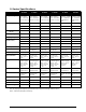
S-Series Specifications Model S-1296 S-1596 S-3294 S-3594 S-215S S-218S Loudspeaker Type Two-way, fullrange, vented bass - switchable passive or bi-amp Two-way, fullrange, vented bass - switchable passive or bi-amp Three-way, fullrange, vented bass - switchable passive or bi-amp Three-way, fullrange, vented bass - switchable passive or bi-amp Dual driver subwoofer, vented bass - switchable hi-pass/parallel output Dual driver subwoofer, vented bass - switchable hi-pass/parallel output Driver Co
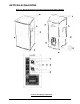
GETTING ACQUAINTED Figure 1: Physical Features of Typical S-Series Full-Range Models S-Series Full-Range Input Panel Community S-Series - Operation and Installation Manual - Page 10
PHYSICAL FEATURES OF S-SERIES FULL-RANGE MODELS FEATURE DESCRIPTION TOP & BOTTOM RIGGING POINTS 8 total, 4 top and 4 bottom - bottom points not shown1 (note: S-SERIES-1296 has 3 top and 3 bottom). ERGO-GRIP SIDE LIFTING HANDLES 2 total. PROTECTIVE GRILLE Powder-coated steel grille protects drivers from foreign objects. GRILLE RETENTION SCREWS Eight (or ten) #6 x 5/8” sheet metal screws, depending on model. REAR ERGO-GRIP LIFTING HANDLE 1 total.
Figure 2: Physical Features of Typical S-Series Subwoofers (Note: the S-215S Subwoofer is not equipped with wheels) S-Series Subwoofer Input Panel Community S-Series - Operation and Installation Manual - Page 12
PHYSICAL FEATURES OF S-SERIES SUBWOOFERS FEATURE DESCRIPTION LIFTING HANDLES 4 total; 2 on each end panel. ‘HANDTRUCK’ HANDLES 2 total. For tilting the enclosure onto its built-in transport wheels (model 218S only). RIGGING POINTS MODEL S-218S: 4 total; 2 on each end panel2. MODEL S-215S: 8 total; 4 on each end panel3. POLE SUPPORT RECEPTACLE Installed on top of enclosure. Accepts standard loudspeaker support pole (1.375” / 35 mm diameter).
GENERAL DESCRIPTION S-Series loudspeakers are designed for demanding day-to-day use in a wide range of both portable applications and fixed installations. Their high quality driver components are housed in rugged, acoustically inert enclosures fitted with convenient carrying handles, rigging fittings, and support stand receptacles. S-Series is characterized by a high-power, low distortion linear response that provides exceptional musicality and speech intelligibility.
IMPORTANT: If the operator continues to run the system at excessive levels, or worse, if the operator raises the drive level to compensate for the drop in output caused by the protection circuitry, eventually an additional stage of protection will engage that shuts down the system entirely (note that this additional stage of protection will never engage until after the second stage has been triggered).
Figure 3: Graph Depicting Frequency Response of MUSIC / VOICE Presence Switch (Note: the Voice/Speech position is represented by the dotted line) Resolution <500 Hz = 10 Hz, >500 Hz = 40 Hz, 1/2 octave smoothing 110 100 90 dB 80 SPL 70 10 100 1,000 10,000 100,000 Frequency in Hertz C-TIP: The VOICE-SPEECH (+4dB) position may be useful when trying to compensate for absorption loss over very long distances, or just when some additional presence is needed to achieve the tonal quality you’re seeking.
Figure 4: Graph Depicting Response of HIGH-PASS / FLAT Switch (Note: upper line depicts HIGH-PASS; lower line depicts FLAT) HIGH-PASS position FLAT position In addition to presenting a more amplifier-friendly load, the HIGH-PASS OUTPUT also attenuates the low-frequency energy that’s fed to the full-range loudspeaker. This reduces the demand on the full-range loudspeaker’s woofer, thereby freeing up some additional power and headroom in the upper part of the bass spectrum.
COOL-COIL™ TECHNOLOGY The cone drivers used in the S-Series subwoofers utilize Community’s patented Cool-Coil™ heat evacuation technology. A proprietary process, Cool-Coil employs an airflow director to remove heat from the voice coil, thereby increasing both the performance and reliability of the cone drivers. In particular, the effect of Power Compression is significantly improved by Cool-Coil technology.
In PASSIVE mode one amplifier is used to power the entire loudspeaker. In BI-AMP mode one amplifier is used to power the low frequency section and another is used to power the high frequency section. The separation of high and low frequencies is done internally in the loudspeaker, so no electronic crossover is required. Simply run full-range signals into the amplifiers and connect the outputs to the appropriate HF and LF terminals on one of the Neutrik input jacks.
USING PROTECTIVE LIMITERS Although S-Series loudspeaker systems are well protected against potentially abusive operating conditions by their internal DYNA-TECH protection circuits, the use of an active, outboard limiter can add an extra measure of insurance for long-term reliability. Additionally, an active outboard limiter can be adjusted to provide a subtler degree of driver protection, precisely tailored to each user’s specific needs in terms of musical styles and operating conditions.
Following is a brief discussion on using limiters to protect loudspeaker systems: • The limiter should be set so that it provides some measure of gain reduction before the amplifier(s) begin to clip. If the limiter is set so that it allows the amplifier(s) to go into hard clipping, it will do little to protect the drivers, except perhaps in the event of extended microphone feedback. • If the system is large enough to handle the intended musical style in the size of room that it’s designed to cover, i.e.
CONNECTING THE AMPLIFIER TO THE LOUDSPEAKER All S Series loudspeakers come with two methods of connecting the amplifier to the loudspeaker. One is a pair of industry standard NL4 type locking connectors, and the other is a pair of ¼” jacks. With the exception of the S-Series subwoofers, which feature a switchable High-Pass output, the four connectors are wired in parallel with each other on all full-range models. When there’s a choice, we recommend using the NL4 type connectors whenever possible.
Figure 6: S-Series Full-Range Input Panel The following figure is an example of the input panel used on full-range S-Series loudspeakers.
PIN DESIGNATIONS In Passive Mode the pin designation is as follows: • • NL4 Pin 1+ and the tip of the ¼” jack connect to the positive (red) output of the amplifier. NL4 Pin 1- and the sleeve of the ¼” jack connect to the negative (black) output of the amplifier. Internally, these pins are connected to the passive crossover in the loudspeaker. Note: Pin 1+ and 1- and Pin 2+ and 2- are always connected in parallel to the second NL4 connector.
Figure 7: S-Series Subwoofer Input Panel The following figure is an example of the input panel used on S-Series subwoofers. Subwoofer Input Panel (Typical) PIN DESIGNATIONS In the Parallel Output Mode the pin designation is as follows: • • NL4 Pin 1+ and the tip of the ¼” jack connect to the positive (red) output of the amplifier. NL4 Pin 1- and the sleeve of the ¼” jack connect to the negative (black) output of the amplifier.
WIRING NEUTRIK TYPE CONNECTORS The diagrams below show how connections are made to a Neutrik SpeakonTM style loudspeaker connector. Terminations may be soldered, or made by means of their built-in screw and pressure clamp. If using the pressure clamp, it’s important to tighten it fully, then to wait about ten minutes (longer is better), then to tighten it again. This is because copper wire flows under pressure.
Impedance and Paralleling Loudspeakers Loudspeakers of identical type may be connected together on the same amplifier. This forms a parallel circuit. When two loudspeakers are connected in parallel, the nominal impedance of the circuit will divide in half. For example, if two 8 ohm loudspeakers are wired in parallel, the result will be a 4 ohm load and the power from the amplifier (voltage x current) will be divided equally between both.
covered with a variety of jacket types. Jackets may be made of PVC, rubber, neoprene, and other materials, depending on the intended conditions of use. Generally speaking, the wires and cables that power loudspeakers do not need to be twisted into pairs, though there is some benefit to doing so.
Below is a table that gives a quick look at the effect of wire size on line loss. These numbers assume that the amplifier is producing a constant 48 Volts at its output terminals, which is equivalent to 288 watts into 8Ω or 576 watts into 4Ω: Size Length Load Z Loss in dB #10 AWG 100’ 8Ω -0.42 dB #10 AWG 200’ 8Ω -0.83 dB #10 AWG 100’ 4Ω -0.83 dB #10 AWG 200’ 4Ω -1.58 dB #12 AWG 100’ 8Ω -0.66 dB #12 AWG 200’ 8Ω -1.28 dB #12 AWG 100’ 4Ω -1.28 dB #12 AWG 200’ 4Ω -2.
C-TIP: Although it’s beyond the scope of this manual to test and rate the many specialty loudspeaker cables sold in audio shops, studies conducted by skilled engineers have conclusively shown that the majority of such cables offer no real performance advantages (and in some cases, notable disadvantages) over that of good quality industrial grade wire. SELECTING AMPLIFIERS Amplifiers are a vital part of any sound system’s performance capability.
Most waveforms that occur in music and speech are the complex conjugate of sine and triangle waves. Such waveforms have a relative short duty cycle, cresting to maximum voltage for only a small part of each cyclic repetition. When an amplifier clips, it’s because it’s reached its maximum voltage potential, so it starts to square off the crest of the waveforms. This more or less turns the waveform into a square wave.
falls below the amplifier’s nominal rating (this is sometimes referred to as a brown-out), and they may shut down or be damaged if the AC voltage suddenly increases. Conversely, those that are built around switching-type power supplies may be tolerant of a drop in AC mains voltage with no loss of output capability. They may also be tolerant of an increase in AC voltage that’s well above nominal.
General Application Guidelines In choosing the right S-Series product for your application, the initial factors to consider are the size of the venue, the style of music and speech to be reproduced, and the location(s) of the loudspeaker(s). In smaller venues with less demanding musical styles, one can usually achieve excellent results with either of the two smaller S-Series models.
Second, the substantial length of low-frequency waves can make it difficult to distinguish their source direction. This is why a single subwoofer can often be used successfully to augment a stereo pair of mid-high loudspeakers, without unduly harming the stereo separation and image. Third, low-frequency waves tend to add together quite graciously, even if their sources are separated by considerable distances, as long as they are in phase with each other.
loudspeaker(s), such location may result in the subwoofer being drastically out of time sync with one or more of the full-range speakers. Sometimes the sound quality of a wall or corner placement is not desirable, simply due to the room’s acoustical properties. Keep in mind that when wall and corner locations are appropriate for use they’ll provide a tremendous increase in power output, but they may not always be the best choice.
subwoofer. This would be true if the full-range system is a very small loudspeaker, like those that are used for front-fill and underbalcony fill. (2) The placement of the subwoofer in relation to the full-range loudspeaker is not optimum. Little or no response variation will occur if the physical relationship results in an approximate ¼ wavelength of offset at the center of the crossover frequency. The solution to (1) is for both systems to remain in positive polarity.
reducing the power that’s required to obtain a given sound pressure level. This will result in more available power, more headroom and less demand on the drivers, all of which lowers the potential for distortion and damage under high power conditions. Now that you’ve chosen the final physical locations for your full-range loudspeakers and subwoofers, established their optimum phase relationship, and brilliantly EQ’d any crossover peaks, you’re almost ready to permanently wire the system.
So here we have a loudspeaker installed in a room. We already know that this loudspeaker exhibits a flat response in a free field environment, such as outdoors or in an anechoic chamber. But what happens when it’s installed in a room? Logic dictates that whatever changes occur to the response of the loudspeaker in the room, are dependant entirely on the effect of the room (unless, of course we wired the loudspeaker wrong, or broke it in transit…which we didn’t).
bumps, and an overall drop that looks like the inverse of the low-frequency rise. You feel a little like Alice in Wonderland. When the equalizer was switched in, the filters actually improved the phase response! You’ve got to get your hands on one of these FFT things, and soon. ### OK. Let’s put this event into more scientific terminology. Here’s what’s happening: The loudspeaker is transferring its acoustic energy into the room.
dB greater in intensity than another, but will not be identified as the location that the sound is coming from, if it arrives later than the lower intensity source. This effect can be used to make underbalcony, overbalcony, and other delayed loudspeakers acoustically ‘disappear,’ drawing the listener’s attention to the stage rather than to the ancillary delay speaker.
RIGGING GUIDELINES The following guidelines on rigging are not intended as a comprehensive rigging manual, nor are they meant to replace the knowledge of safe rigging practices that might be obtained from receiving professional training on the subject. These guidelines are intended only to provide basic safety information, and to call your attention to some commonly made mistakes.
mounted on a cruise ship or in a venue located near sea water), or in conditions involving high-vibration, high wind-loads, or other unusual conditions. A common safety factor is a 6:1 ratio; however many theatrical rigging companies voluntarily work at a 7:1 ratio or higher. A 10:1 ratio is required in most countries that are members of the European Union. At a 10:1 ratio, this means that a component rated at 10,000 lbs of ultimate strength should never be subjected to a load greater than 1,000 lbs.
4. Load Angles This is an area that is often misunderstood, so let’s clear it up. Whenever an object is suspended from one point, it has no choice but to hang directly below that point of suspension; in other words at a zero degree angle to the suspension point. When an object is suspended from more than one point, the points may or may not be at zero degrees to the suspension point. When the suspension points are not at zero degrees to the object, they form a bridle.
5. Wire Rope Clips Wire rope clips, sometimes called “Crosbys” after one manufacturer, should always be of the drop-forged type, never of malleable steel. They must always be installed in accordance with the manufacturer’s instructions and specifications.
only 30% of its rated strength. At 90º it is de-rated to only 25%. Use at angles steeper than 45° is strongly discouraged. Such use would be permissible for breasting back a loudspeaker to alter its downward angle, where the breast line is not part of the suspension system nor is it considered to be the safety cable. Vertically rigging a loudspeaker from eyebolts placed into its side surfaces (90º) must always be avoided.
10. Support Points & General Practices A vital part of planning the mounting or suspension system is to first determine the strength of the building’s support points. Nothing should be assumed, even for the lightest loads. A ten pound loudspeaker falling from ten feet can maim or kill just as readily as a heavy loudspeaker array falling from thirty feet.
S-SERIES RIGGING AND MOUNTING HARDWARE Below are descriptions of mounting brackets and suspension kits manufactured by Community for use with S-Series loudspeakers. In this section the terms “suspension” and “fly” mean the same thing: to elevate the loudspeaker enclosure above the ground surface. IMPORTANT: All rigging fittings should remain sealed, otherwise air leaks will occur in the enclosure that can compromise the low-frequency performance with distortion and reduced output.
STKIT Assembly Instructions CAUTION: Before assembling the Seat Track Channels to the loudspeaker enclosure, note that the kit is supplied with both 3/8-16 Unified Course and 10mm Metric fasteners. These fasteners are very similar but they are NOT identical. It is critically important that you use fasteners with the proper thread pitch. All S- Series loudspeakers use the M10 metric fasteners. DO NOT USE THE 3/8-16 UNC FASTENERS! It is very easy to mistake one thread pitch for the other. 1.
Figure 15: STKIT Assembly of S-Series Enclosure with 4 Seat Track Channels and M10 Hardware (4) 8 x 1" FLATHEAD PHILLIPS D RIVE DEEP THREAD SCREWS (4) FLATHEAD ALLEN DRIVE SCREWS (M10 x 40mm OR 3/8-16 x 1.5”) (4) SEAT TRACK CHANNELS IMPORTANT SAFETY WARNING: The STKIT is supplied with both 3/8-16 Unified Course and 10mm Metric fasteners. These fasteners are very similar but they are NOT identical. It is critically important that you use the M10 fasteners with all S- Series enclosures.
VFKIT Parts List (1) (1) (4) (8) (8) (4) (4) Front Metal Bracket Rear Metal Bracket M10 30mm Bolts M10 Flat Washers M10 Split Lock Washer M10 Eyebolts M10 Hex Nuts The installer must supply all other hardware for the installation. VFKIT Assembly Instructions 1. First, remove the two factory supplied flat-head Allen screws on the inside tops of each enclosure (4 total). 2. Assemble the components of the Vertical Fly Kit as shown in the drawing below.
2. The use of safety points in rigged or ‘flown’ systems is highly recommended. The Vertical Fly Kit includes eyebolts intended for this purpose. The eyebolts should ideally be attached to unused rigging fittings on the tops of the enclosures and connected to safety cables. Safety cables are a second set of ‘backup’ cables that can sustain the load in the event that the primary suspension system fails. Safety cables must always be installed with little to no slack.
Figure 17: Never Reeve Cables! Using More Than One VFKIT More than one Vertical Fly Kit may be used to fly three, four, or more loudspeakers in an array. Simply attach the additional kit(s) to the additional enclosures in the same manner as the first kit. WARNING: When assembling more than two enclosures into an array, it is very important that the suspension cables be installed correctly so as not to place undue stress on either the Vertical Fly Kit or on the enclosures themselves.
It is also permissible to bridle from the front to rear hang points, using a separate bridle for each enclosure. This may have to be done if the hang points in the building are oriented left-to-right instead of upstage/downstage. However, setting the bridles for an upstage/downstage hang, as shown above, provides the advantage of being able to adjust the inclination of the array while it’s in the air.
AVAILABLE ACCESSORIES In addition to the rigging kits described above, these other useful accessories are available for S-Series loudspeakers: Padded Transport Covers Protect your S-Series loudspeakers from scratches and mars.
SERVICING S-SERIES LOUDSPEAKERS Servicing a S-Series loudspeaker is straightforward and easy. All drivers are serviceable by removing the screws that attach the protective grille to the front of the enclosure. The crossover is serviceable by removing the input panel on the rear of the enclosure. There are no other user-serviceable parts. TROUBLESHOOTING GUIDE Should you have a problem with your S-Series loudspeaker(s), find the symptom and follow the associated “What To Do” instructions below.
SYMPTOM PROBABLE CAUSE WHAT TO DO Low volume level. Signal or speaker wire connection is shorted. Make sure the signal and input wire connections inside all system connectors are not shorted or open. Even one small wire strand shorting the +/– signal terminals together anywhere in the system can cause this problem. Sound when BI-AMPLIFIED is “muffled”. PASSIVE / BI-AMP switch is in the wrong position. Switch on the input panel should be in the BI-AMP MODE (RIGHT) position.
REPLACEMENT PARTS The following replacement parts may be ordered through authorized Community Service Stations. Please contact Community for your nearest Service Station.
WARRANTY INFORMATION AND SERVICE Transferable Warranty (Limited) – Valid in the USA Only Community loudspeaker systems are warranted in the USA to be free from defects in materials and workmanship for a period of five years, as determined by one of the following two methods, whichever is longer: 1. Starting from the date of retail purchase, as noted on the sales receipt from an authorized Community dealer, OR 2.
the exclusion or limitations of consequential or incidental damages, so the above limitations and exclusions may not apply. This Community warranty is not extended by the length of time which an owner is deprived of the use of the product. Repairs and replacement parts provided under the terms of this warranty shall carry only the remaining portion of the warranty.
Community Professional Loudspeakers 333 East Fifth Street, Chester, PA 19013-4511 USA Tel: 1-(610) 876-3400 | Fax: 1-(610) 874-0190 www.communitypro.