
Specifications


Community VLF Series – Operation Manual - Page 15
CONNECTING THE AMPLIFIER TO THE LOUDSPEAKER:
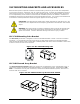
VLF212P
Figure 13: VLF212P Input Panel
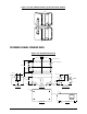
PIN Designations
In the Parallel Output Mode the pin designation is as follows:
NL4 Pin 1+ and the tip of the ¼” jack connect to the positive (red) output of the amplifier.
NL4 Pin 1- and the sleeve of the ¼” jack connect to the negative (black) output of the amplifier.
Internally, each of these pins are connected to the NL4 output connector, to the ¼” output jack, and to the
drivers in the subwoofer.
In the Hi-Pass Mode the pin designation is as follows:
NL4 Pin 1+ and the tip of the ¼” jack connect to the positive (red) output of the amplifier.
NL4 Pin 1- and the sleeve of the ¼” jack connect to the negative (black) output of the amplifier.
Either the NL4 or the ¼" jack on the right side of the input panel may be used as hi-pass outputs to drive
one or more full-range loudspeakers. These hi-pass outputs exhibit the response that is discussed in the
section of this manual entitled “SELECTABLE HIGH-PASS OUTPUTS: VLF212P.”