ComNav R Marine Ltd. CT2-40A MOTOR CONTROLLER PART NUMBER 20350001 DOCUMENT PART NUMBER 29010024 Permanent Magnet z Shunt Field Compound z D.C. Motors ComNav Installation Instructions Version 3.3 ComNav Marine Ltd. #15-13511 Crestwood Place. Richmond, B.C. Canada. V6V-2G1 Telephone: 604-207-1600 Facsimile: 604-207-8008 Web: www.comnavmarine.com E-mail: sales@comnav.
Introduction: CT2-40A Motor Controllers are designed to connect a ComNav Autopilot to a steering system using a permanent magnet, shunt field, or compound reversing D.C. Motor. CT2-40A Motor Controllers feature dynamic braking, current limiting and thermal protection of the MOSFET driving transistors while allowing full power acceleration and drive when needed. CT2 Motor Controllers can be used with 12, 24 and 32 VDC battery systems.
For the correct interconnection of the CT2 Motor Controller and the Autopilot refer to Figures 2 through 4. A four-conductor, #24 AWG cable with shield will be satisfactory. The shield of the cable should be terminated to the JOG COMMON terminal (or V-) in the Autopilot distribution box and unterminated at the other end. If Jog Levers are used to override the Autopilot, connect them to the terminals provided in the Autopilot distribution box (see enclosed diagrams or the Autopilot manual).
TROUBLESHOOTING: • Check with a voltmeter that voltage is present between Terminals J1, V+ and J1, V- (the battery voltage). • If no voltage is present, check that there is power to the breaker panel, and that the breaker for the motor is turned on. Recheck the wiring from the breaker panel to the CT2 Drive Box. • If voltage is present, use an ohmmeter to check the 30 AMP Fuse (F1). Check the 1 AMP Fuse (F2) as well. If either is faulty, replace with the same size fuse.
• If the motor runs: 1. Check the outputs from the Autopilot for correct operation. The red and green output diagnostic LED's in the Autopilot distribution box should come on as described in the ComNav Autopilot Installation and Operation Manual. 2. If the diagnostic LED's do come on and the rudder still will not move, examine the wiring between the Autopilot and the CT2 Motor Controller again. Check for open or short circuits. Check for nails or staples which may have penetrated the cable. 3.
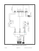
Figure 2 Connection to Permanent Magnet Motor 21/09/2007 Page 5 of 10 29010024V3.3(2T Drive Box).doc 6 MOTOR MONITOR +5V STBD PORT 3 2 1 + M1 M2 FIELD + FIELD - 4 5 6 5 4 3 2 1 10 - 40 VDC MOTOR 3 2 1 + BATTERY 12/24 VDC - 30A FUSE OR BREAKER (NOT SUPPLIED) JOG LEVER 4 3 2 1 JOG COM JOG STBD JOG PORT MOTOR MON (1001,1101,1201) COM +5V SPD CNTL SW. PWR STBD PORT UNSW.
Figure 3 Connection to Shunt Field Motor 21/09/2007 Page 6 of 10 29010024V3.3(2T Drive Box).doc 6 MOTOR MONITOR +5V STBD PORT 3 2 1 + M1 M2 FIELD + FIELD - 4 5 6 5 4 3 2 1 M1 M2 FLD+ FLD- SHUNT FIELD MOTOR 10 - 40 VDC MOTOR 3 2 1 + BATTERY 12/24 VDC - 30A FUSE OR BREAKER (NOT SUPPLIED) JOG LEVER 4 3 2 1 AUTOPILOT JOG COM JOG STBD JOG PORT MOTOR MON (1001,1101,1201) COM +5V SPD CNTL SW. PWR STBD PORT UNSW.
Figure 4 Connection to Compound Motor Page 7 of 10 6 MOTOR MONITOR +5V STBD PORT 4 3 2 1 5 1 FIELD - 6 + 5 4 M1 3 M2 2 FIELD + M1 M2 FLD- + COMPOUND MOTOR 10 - 40 VDC MOTOR 3 2 1 - + SHUNT BATTERY 12/24 VDC - 30A FUSE OR BREAKER RED GREEN 21/09/2007 29010024V3.3(2T Drive Box).doc S E R IE S BLACK W H IT E BROW N (NOT SUPPLIED) JOG LEVER 4 3 2 1 JOG COM JOG STBD JOG PORT MOTOR MON (1001,1101,1201) COM +5V SPD CNTL SW. PWR STBD PORT UNSW.
Figure 5 Connection to Processor Based Autopilots 21/09/2007 Page 8 of 10 29010024V3.3(2T Drive Box).doc TO CT2 BOX 5 TO BAT 12/24/32 VDC U2 1A + M1 M2 F1 20A U3 V BOOST PORT IN STBD IN J2 1 2 M2 3 FIELD+ FIELD- O/C F/B +5V 6 5 M1 4 + - J1 6 5 4 3 2 1 TO +5V TO M2 TO M1 SHOWN WIRE SHOULD BE KEPT INSIDE THE PROCESSOR CASE. +5V CT2 BOX AND PROCESSOR MUST BE COMMON GROUND. TYPICAL CONNECTIONS CT2 BOX TO PROCESSOR BASED AUTOPILOTS.
GND DATA BLACK SHIELD GREEN WHITE WHITE 2 3 4 VR1 (ANTI-HUNT) VR4 VR2 (ANALOG RAI GAIN) S1 GAIN COM 4 FFUS SHIELD WHITE YELLOW GREEN Figure 6 Connection to 1500 Autopilot 29010024V3.3(2T Drive Box).
2 3 4 15 AMP FUSE 5 AMP FUSE VR2 VR3 Page 10 of 10 U2 F2 1A BATTERY 12/24 VDC 5 VR1 F1 1 2 2 VR6 30A S2 DIP SWITCHES ** TO CT2 BOX VR4 S1 1 12 3 WHITE FLUXGATE COMPASS GND DATA GND DATA BLACK WHITE RED SHIELD WHITE YELLOW GREEN SHIELD U3 C17 RUDDER FOLLOWER UNIT (RFU) 24 GREEN YELLOW 1 2 3 4 5 6 7 8 9 10 11 12 13 14 15 16 17 18 19 20 21 22 Figure 7 Connection to 1510 Autopilot 29010024V3.3(2T Drive Box).doc TO PORT IN CT2 REV.