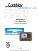
Navigator G2 GPS Compass Display Installation & Operation Manual PN 29010081 www.busse-yachtshop.de | info@busse-yachtshop.
www.busse-yachtshop.de | info@busse-yachtshop.
ComNav Navigator G2 Installation & Operation Welcome Welcome Congratulations on your purchase of ComNav Marine’s Navigator G2 GPS Compass Display! At ComNav, we are proud of our prominence as a leader in the design and manufacture of marine autopilot systems. Our dedication to performance and reliability will ensure your satisfaction with the Navigator G2. ComNav Marine Ltd.
ComNav Navigator G2 Installation & Operation Welcome Document History Revision Date By Description 0R9 7-3-2008 G Initial release from eMotion 1R0 7-3-2008 J First release 1R1 31-3-2008 J The system only works on 12 VDC system Document PN 29010081 V1.1 -2- www.busse-yachtshop.de | info@busse-yachtshop.
ComNav Navigator G2 Installation & Operation Table of Contents Table of Contents Welcome .......................................................................................................................................................1 Document History.....................................................................................................................................2 Table of Contents ..................................................................................................
ComNav Navigator G2 Installation & Operation Table of Contents Appendix 2 .................................................................................................................................................48 Wiring Reference for ComNav Standard Cables___________________________________________________ 48 Appendix 3 .................................................................................................................................................
ComNav Navigator G2 Installation & Operation Tables & Figures List of Figures Figure 1 – Vector G2 System Connections ....................................................................................................................9 Figure 2 – Vector G2 GPS Compass ...........................................................................................................................10 Figure 3 - Navigator G2 Display Head ..............................................................................
ComNav Navigator G2 Installation & Operation Document PN 29010081 V1.1 -6- www.busse-yachtshop.de | info@busse-yachtshop.
ComNav Navigator G2 Installation & Operation Introduction Document PN 29010081 V1.1 -7- www.busse-yachtshop.de | info@busse-yachtshop.
ComNav Navigator G2 Installation & Operation Document PN 29010081 V1.1 -8- www.busse-yachtshop.de | info@busse-yachtshop.
ComNav Navigator G2 Installation & Operation Introduction Overview of the Navigator G2 The Navigator G2 is designed to work with ComNav’s Vector GPS compasses, and other NMEA devices.
ComNav Navigator G2 Installation & Operation Introduction Vector Series GPS Compass A Vector Series GPS Compass uses multiple GPS antennas and sensors to accurately sense vessel position, heading, pitch, and roll. A Vector Series compass communicates NMEA 0183 information out two data ports. Both RS232 and RS422 signal level outputs are supported.
ComNav Navigator G2 Installation & Operation Introduction Distribution Unit The G2 Distribution Unit provides a convenient location to terminate and distribute signals from the Vector Series GPS Compass.
ComNav Navigator G2 Installation & Operation About this Manual This manual provides essential information for the safe and reliable operation of the ComNav Navigator G2 GPS Compass Display. You are urged to read this manual in its entirety before you use your Navigator G2 the first time, and to keep it handy until you become thoroughly familiar with the operation.
ComNav Navigator G2 Installation & Operation Installation Document PN 29010081 V1.1 - 13 - www.busse-yachtshop.de | info@busse-yachtshop.
ComNav Navigator G2 Installation & Operation Document PN 29010081 V1.1 - 14 - www.busse-yachtshop.de | info@busse-yachtshop.
ComNav Navigator G2 Installation & Operation Installation Installation Technical Requirements The following are the basic technical requirements that should be met before installation of the Navigator G2 on your vessel. Caution Please refer to the Warranty Information this manual before proceeding with installation of the Navigator G2.
ComNav Navigator G2 Installation & Operation Installation Electrical Connections The G2 Distribution Unit contains five (5) terminal blocks to connect signals from: • • • • Ship Power, Vector G2, Display Heads, and external NMEA devices. Figure 5 shows the location of each block in a distribution unit.
ComNav Navigator G2 Installation & Operation Installation Figure 6 - Terminal Connection - Step 1 Figure 7 - Terminal Connection - Step 2 Document PN 29010081 V1.1 - 17 - www.busse-yachtshop.de | info@busse-yachtshop.
ComNav Navigator G2 Installation & Operation Installation Terminal Strip Labels The Distribution Unit uses two-tier, spring loaded terminal strips. The silk screen labels on the Printed Circuit board (PCB) identify terminal functions. Figure 8 below shows how the labels on the PCB map to the terminals on the connector blocks. Upper Tier Lower Tier Figure 8 - Terminal Connection Silk Screen Labels Document PN 29010081 V1.1 - 18 - www.busse-yachtshop.de | info@busse-yachtshop.
ComNav Navigator G2 Installation & Operation Installation Vector G2 Terminals Table 1 below lists the different signals and wire codes in the cable coming from a Vector G2 GPS Compass. Table 1 – Vector G2 Wiring and Connections Description Color Codes Color Codes 051-0063-004 051-0157-002 051-0098-001 051-0158-001 Bare Wire Bare Wire Drain for RF Shielding – Do Not Connect – Cut and Remove the exposed Bare Wire White n/a Do Not Connect PWR Red (18 AWG) Red (18 AWG) Power Input to Vector.
ComNav Navigator G2 Installation & Operation Installation Ship Power Display Head Switched Power Figure 9 – Vector G2 Power Connection - Always On or Switched The Vector G2 Power wires can be connected to two (2) different sets of terminals, depending on your vessel, and what other NMEA devices are receiving data from the Vector, as shown in figure 9.
ComNav Navigator G2 Installation & Operation Installation Display Head Terminals (#1 and #2) Table 2 below lists the different signals in the Display Head cable which goes out to each Display Head.
ComNav Navigator G2 Installation & Operation Installation NMEA Output Terminal Table 3 below lists all of the NMEA and status signals located on the NMEA Terminal Strip. All external device connections must me made on this terminal strip.
ComNav Navigator G2 Installation & Operation Installation Ship Power Bus Terminal Ship Power into the Distribution Unit must connect to the Power Bus block. The Distribution Unit protects the Vector and Display Head power from Ship Power over voltage and reverse voltage faults. It is important that the Vector and Display Heads receive their power input from the protected power connections on their connector block.
ComNav Navigator G2 Installation & Operation Document PN 29010081 V1.1 - 24 - www.busse-yachtshop.de | info@busse-yachtshop.
ComNav Navigator G2 Installation & Operation Operation Document PN 29010081 V1.1 - 25 - www.busse-yachtshop.de | info@busse-yachtshop.
ComNav Navigator G2 Installation & Operation Document PN 29010081 V1.1 Operation - 26 - www.busse-yachtshop.de | info@busse-yachtshop.
ComNav Navigator G2 Installation & Operation Operation Basic Operation This section describes the basic modes of operation of the G2 Display Head. Power On/Off To turn on … • • • • • Press Control Head On/Off Switch . Verify that the Distribution Unit Switched Power LED is ON. Verify that the Control Head LCD powers up. Verify that the Distribution RS232A and RS232 B Active LEDs begin to pulse. Verify that values begin to display on the Control Head as the GPS acquires satellites.
ComNav Navigator G2 Installation & Operation Operation Display Controls Color Display Backlight and Day/Night Adjustment The Color Display Head is able to change both the backlight level, and active color scheme. Colors can switch between: • • Day (Black on Blue background), and Night (Red on Black background). The UP/DOWN Arrows buttons are used to increase the backlight level and change between Day and Night color schemes.
ComNav Navigator G2 Installation & Operation Operation Monochrome Display Contrast and Backlight Adjustment The Monochrome Display Head is able to change both the LCD contrast, and the backlight for the buttons. Contrast and backlight must be adjusted separately. See figure 13. The UP/DOWN Arrows buttons are used to change the LCD Contrast level. The CLR/FN buttons are used to adjust the button backlight levels.
ComNav Navigator G2 Installation & Operation Operation Normal Usage The G2 Display Head provides graphical and text information about the vessel position and attitude (speed, heading, turn rate). Two (2) Display Heads can be driven from a single Distribution Unit. The G2 display provides three different levels of display pages. The first level pages (DISP mode) shows information typically used during vessel operation including graphical and text displays of vessel operation.
ComNav Navigator G2 Installation & Operation • • • • • Operation Position – GGA or RMC Heading – HDT, HDM, or HDG Speed and Course – VTG or RMC Rate of Turn - ROT Satellite Information – GSA or GSV Display Pages There are three pages which can be selected by toggling the DISP button – Graphical, Text and Position pages. All pages show status information on the Left side of the screen. The status information indicates the quality of the GPS data display.
ComNav Navigator G2 Installation & Operation Operation True (HDT) or Magnetic (HDM) Heading Heading (degrees) Status Dilution of Precision and Time Course Over Ground (degrees) Speed Over Ground (knots) Turn Direction (Port or Stbd) Turn Rate (degrees/ minute) Figure 16 - Text Navigation Page Description True (HDT) or Magnetic (HDM) Heading Latitude Decimal Minutes Status Dilution of Precision and Time PositionLatitude, Longitude (degrees) Heading (degrees) Longitude Decimal Minutes Speed Over
ComNav Navigator G2 Installation & Operation Operation Table 4 – Navigation Page Fields Descriptions Field Description NMEA Message Source Heading Heading in units of degrees. True (HDT) or Magnetic (HDM) depending on the NMEA sentences being received. HDT, HDM, HDG COG Course Over Ground. Displayed in Units of degrees. VTG, RMC SOG Speed Over Ground. Displayed in Units of knots. VTG, RMC ROT Rate of Turn of the vessel. Displayed in Units degrees per minute.
ComNav Navigator G2 Installation & Operation Operation Figure 18 - Heading Information Page Description Table 5 – Heading Information Page Fields Descriptions Field Description NMEA Message Source Heading Heading angle in units of degrees. ‘T’ if True Heading. ‘M’ if Magnetic Heading. HDT, HDM, HDG Deviation Heading Deviation in units of degrees. ‘E’ for East adjustment. ‘W’ for West adjustment. HDG Variation Heading Variation in units of degrees. ‘E’ for East adjustment.
ComNav Navigator G2 Installation & Operation Operation The GPS Status page displays detailed GPS information including: • • • • • • Dilution of Precision Values Number of Satellites in the solution and in view Type of Solution Fix Differential GPS Station and Age UTC Date and Time Latitude and Longitude Figure 19 shows an example of the GPS Status page. Table 6 gives which NMEA sentences these information comes from.
ComNav Navigator G2 Installation & Operation Operation The GPS Satellite page displays satellite position information for up to eight (8) satellites with strong signal levels. Satellites are displayed in ascending order using the Satellite ID number. Information includes: • Satellite elevation above the horizon • Azimuth angle relative to True North • Signal strength The information in this page comes from NMEA sentence GVS. Figure 20 shows an example of the GPS Satellite Information page.
ComNav Navigator G2 Installation & Operation Operation Parameter Setup Pages The SETUP pages allow you to change parameters within the G2 Vector GPS Compass.
ComNav Navigator G2 Installation & Operation Operation You can only select a message rate permitted by the G2 Series compass for message you have selected. • • • • • All messages can be sent at 1.0 Hz or one (1) message per second. All messages can be sent at 0.2 Hz or one (1) message every five (5) seconds. Certain messages can be transmitted at 5.0 Hz or five (5) messages per second. Certain messages can be sent at 10.0 Hz or ten (10) messages per second. A message rate of 0.
ComNav Navigator G2 Installation & Operation Operation The Filter Smoothing and Sensor Aids page allows the GPS sensor filtering to be adjusted to match your vessel dynamics. Figure 24 shows an example of the Filter and Aids page. Figure 24 - Smoothing Filters and Aids Page The Pitch/Roll page allows specific performance of the G2 Vector Pitch/Roll sensor to be configured. It also displays Firmware information about the Control Head and the Distribution Unit.
ComNav Navigator G2 Installation & Operation Document PN 29010081 V1.1 - 40 - www.busse-yachtshop.de | info@busse-yachtshop.
ComNav Navigator G2 Installation & Operation Care & Maintenance Document PN 29010081 V1.1 - 41 - www.busse-yachtshop.de | info@busse-yachtshop.
ComNav Navigator G2 Installation & Operation Document PN 29010081 V1.1 - 42 - www.busse-yachtshop.de | info@busse-yachtshop.
ComNav Navigator G2 Installation & Operation Care & Maintenance Care & Maintenance The Navigator G2 GPS Compass Display has been designed to provide many years of reliable service. The following periodic care and maintenance tips will help to ensure the longevity of your GPS Compass Display. Cleaning and Appearance The Control Head should be carefully cleaned on are regular basis with a damp cloth and mild soap. Do not use abrasive cleaners or chemicals.
ComNav Navigator G2 Installation & Operation Document PN 29010081 V1.1 Operation - 44 - www.busse-yachtshop.de | info@busse-yachtshop.
ComNav Navigator G2 Installation & Operation Appendices Document PN 29010081 V1.1 - 45 - www.busse-yachtshop.de | info@busse-yachtshop.
ComNav Navigator G2 Installation & Operation Document PN 29010081 V1.1 - 46 - www.busse-yachtshop.de | info@busse-yachtshop.
ComNav Navigator G2 Installation & Operation Appendices Appendix 1 Troubleshooting This section lists many of the common problems which you may encounter while installing and operating your Vector Series Navigator system. It also identifies potential causes and how to use the diagnostic indicators to narrow down the source of the problem. Symptom Possible Cause Power LED Off • Ship Power not connected • Ship Power Breaker OFF • Ship Power polarity (B+,B-) are reversed.
ComNav Navigator G2 Installation & Operation Appendices Appendix 2 Wiring Reference for ComNav Standard Cables The drawing in the next page is a wiring reference with color code for ComNav standard cables for Vector and Display Head Document PN 29010081 V1.1 - 48 - www.busse-yachtshop.de | info@busse-yachtshop.
www.busse-yachtshop.de | info@busse-yachtshop.
ComNav Navigator G2 Installation & Operation Document PN 29010081 V1.1 Appendices - 50 - www.busse-yachtshop.de | info@busse-yachtshop.
ComNav Navigator G2 Installation & Operation Appendices Appendix 3 Wiring Termination in the Distribution Unit This section describes the best practices to terminate and connect the wiring harnesses into the Navigator Distribution Unit Two-Tier Terminal Strips. You may choose to do this if you shorten a wire harness to the length required on your vessel.
ComNav Navigator G2 Installation & Operation Appendices Figure 27 - Cable Shield Removal Figure 28 - Wire Insulation Removal Document PN 29010081 V1.1 - 52 - www.busse-yachtshop.de | info@busse-yachtshop.
ComNav Navigator G2 Installation & Operation Appendices Appendix 4 General Specifications Table 7 – Display Head General Specification Parameter Specification Dimensions 155 x 113 x 29 mm, without knob (6.1 x 4.4 x 1.1”) Color Gray Operating Temperature Range -30º to +80º C (-20º to 175º F) Cable Length (Max) 7.6 m (25’) To Distribution Unit Table 8 – Distribution Unit General Specification Parameter Specification Dimensions 180 x 160 x 60 mm (7.1 x 6.2 x 2.
ComNav Navigator G2 Installation & Operation Document PN 29010081 V1.1 Appendices - 54 - www.busse-yachtshop.de | info@busse-yachtshop.
ComNav Navigator G2 Installation & Operation Warranty Document PN 29010081 V1.1 - 55 - www.busse-yachtshop.de | info@busse-yachtshop.
ComNav Navigator G2 Installation & Operation Document PN 29010081 V1.1 - 56 - www.busse-yachtshop.de | info@busse-yachtshop.
ComNav Navigator G2 Installation & Operation Warranty Information Limited Warranty This Limited Warranty (the “Warranty”) covers all Vector and Navigator GPS Compass products & accessories (the “Equipment”) sold by ComNav Marine Ltd. (“ComNav”).
ComNav Navigator G2 Installation & Operation 3. ComNav reserves the right to modify the Equipment without any obligation to notify, supply or install any improvements or alterations to existing Equipment.
ComNav Navigator G2 Installation & Operation CUSTOMER REMEDIES 1. If the Equipment, or any part thereof, proves to be defective within the warranty period, the Purchaser shall do the following: a. contact ComNav, by phoning 604-207-1600, to discuss the nature of the problem and to obtain return shipping instructions for the defective Equipment; and, b.
ComNav Navigator G2 Installation & Operation WARNING The Equipment is an aid to navigation only. It is not intended or designed to replace the person on watch. A qualified person should always be in a position to monitor the vessel’s heading, and to watch for navigational hazards, and should be prepared to revert to manual steering immediately if an undesired change of heading occurs, if the heading is not maintained within reasonable limits, or when navigating in a hazardous situation.
ComNav Navigator G2 Installation & Operation User Notes Document PN 29010081 V1.1 - 61 - www.busse-yachtshop.de | info@busse-yachtshop.
User Notes ComNav Navigator G2 Installation & Operation User Notes Table 9 – User Notes Document PN 29010081 V1.1 - 62 - www.busse-yachtshop.de | info@busse-yachtshop.