
Installation Manual

INS_CLFE4+2SMS[POE](C,U)_REV– 10/27/11 PAGE 6
INSTALLATION AND OPERATION MANUAL CLFE4+2SMS[POE](C,U) SERIES
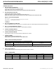
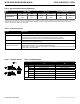
1 Mixed PoE and Non-PoE systems can be implemented.
2 Lower data rates generally provide longer operating distances.
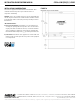
Application notes
INSTALLATION AND OPERATION MANUAL CLFE4+2SMS[POE](C,U) SERIES
TECH SUPPORT: 1.888.678.9427
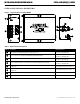
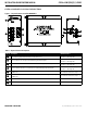
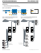
Figure 6 – Application Diagram Without Multicast Traffic
IGMP Disabled, Uplink disabled on the units.
CL1
PC Connections
on Ports P1-P4
CLFE4+2SMS(C,U)
CLFE4+2SMS(C,U)CLFE4+2SMS(C,U)
CL1
CL1
CL2
Figure 4 – Typical Application
Figure 5 – Application Diagram With Multicast Traffic
IGMP Enabled, Uplink enabled on the units
CL1
PoE Camera
Connections
on Ports P1-P4
CNGE3FE7MS2
CNGE3FE7MS2
CLFE4+2SMS(C,U)
CLFE4+2SMSPOE(C,U)
CLFE4+2SMS(C,U)
CL1
CL1
CL2
Up-layer Network
CL(X)-SFP CL(X)-SFP
CL(X)-SFP CL(X)-SFP
Up-layer Network
CLFE4+2SMSC
6 5
1 2
3 4
CLFE4+2SMSPOEC
65
1 2 3
4
12VDC
CLFE1EOC
E E
E
E EE EE E
PoE
PoE Devices
Power
Power
Power
Coax/UTP
Legend
CAT5e/6 Cable
PoE Power