
Installation Manual

INS_CLFE4+2SMS[POE](C,U)_REV– 10/27/11 PAGE 3TECH SUPPORT: 1.888.678.9427
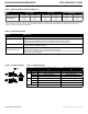
CLFE4+2SMSPOEU PHYSICAL DESCRIPTION
INSTALLATION AND OPERATION MANUAL CLFE4+2SMS[POE](C,U) SERIES
TECH SUPPORT: 1.888.678.9427
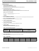
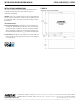
Table 1 – Physical Feature Descriptions
Call-out Description Manual Reference
1
Power Indicating LED (Unlabeled LED Reserved for Future Use) See Table 3 - Indicating LEDs
2
10/100 TX RJ-45 Ports 1 through 4 and Link/Activity (L/A) Indicating LEDs
See Installation Instructions, Step 5
See Table 3 - Indicating LEDs
3
Channel 1 Extended Distance over UTP RJ-45 Port and Link/Activity (L/A) Indicating LED
See Installation Instructions, Step 4
See Table 3 - Indicating LEDs
4
Channel 2 Extended Distance over UTP RJ-45 Port and Link/Activity (L/A) Indicating LED
See Installation Instructions, Step 4
See Table 3 - Indicating LEDs
5
Channel 1 Extended Distance over UTP Port DIP Switches for Local/Remote Operation, Data Speed,
and Wire Pairs
See Installation Instructions, Steps 1 – 3
6
Channel 2 Extended Distance over UTP Port DIP Switches for Local/Remote Operation, Data Speed,
and Wire Pairs
See Installation Instructions, Steps 1 – 3
7
Channel 1 Extended Distance over UTP Uplink DIP Switch See Installation Instructions, Step 6
8
PoE Power Connections See Installation Instructions, Step 7
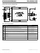
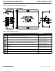
Figure 1 – Physical Features of CLFE4+2SMSPOEU
1
2
3
4
5
6
8
7