
User Manual

INS_CNFE100(X)_REV–
01/04/10
PAGE 4
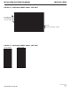
FIGURE 7 – LED INDICATORS
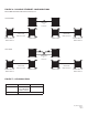
FIGURE 6 – POSSIBLE ETHERNET CONFIGURATIONS
Ethernet IEEE 802.3
Network Element
Ethernet IEEE 802.3
Network Element
Ethernet IEEE 802.3
Network Element
Ethernet IEEE 802.3
Network Element
CNFE1002M1A
CNFE1003M2A
CNFE1002M1B
CNFE1003M2B
CAT5e/6 with
RJ45 Connections
CAT5e/6 with
RJ45 Connections
CAT5e/6 with
RJ45 Connections
CAT5e/6 with
RJ45 Connections
Optical Fiber
ST
Connectors
Optical Fibers
SC
Connectors
Ethernet IEEE 802.3 Network Element determined by user.
SINGLE FIBER
TWO FIBER
LINK POWER
GREEN
Ethernet link has
been established at
the RJ45 connector.
Unit powered up
OFF
Unit Powered Down