
Installation Manual

INS_CNFE200X[POE] Series_REV– 10/18/14 PAGE 5
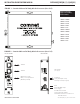
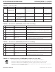
FIGURE 7 – Indicating LEDs
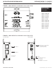
FIGURE 8 – DIP Switches (CNFE200(X) Standard Size Units Only)
LINK STATUS (See Figures 8 & 9) POE 1 & 2 (PoE models only) POWER ETHERNET LINK/ACTIVITY
GREEN Communication link has
been established over
optical fiber. Flashes when
data is being transmitted.
No Fault conditions detected PoE power provided on port Unit is correctly powered up CNFE200(X) unit is
operational
YELLOW N/A Fault detected (PoE models)
(One or more DIP Switch relays
must be enabled)
N/A N/A Fiber failure or copper
failure (Link Fault DIP Switch
must be Enabled / ON)
RED N/A Fault detected (non-PoE models)
(One or more DIP Switch relays
must be enabled)
N/A N/A N/A
OFF Communication link has
not been established.
Unit not correctly powered up PoE power not provided. Unit not correctly powered up Unit not correctly powered
up.
SW NAME OFF (DOWN) ON (UP)
1 LINK FAULT ENABLE PORT 1
Link Fault Pass-Through Disabled
Link Fault Pass-Through Enabled.If the Copper Port is Down or Not Connected, the
Optical Port will turn on and off at a ~1 sec rate to indicate copper port 1 fault.
2 LINK FAULT ENABLE PORT 2
Link Fault Pass-Through Disabled
Link Fault Pass-Through Enabled.If the Copper Port is Down or Not Connected, the
Optical Port will turn on and off at a ~1 sec rate to indicate copper port 2 fault.
3 FFE Fiber Fault Relay Disabled
Fiber Fault Relay Enabled. If the optical link is lost or there is a power failure then the alarm
relay output will be triggered.
4 MUX MUX Disabled
Mux Enabled. All Ethernet traffic is diverted from the copper ports to the fiber port,
copper-to-copper traffic will be disabled.
5 DEMUX DEMUX Disabled
DeMux Enabled. When two CNFE200(X) units are connected via fiber and both have DeMux
enabled, traffic from Port 1 will go to Port 1 and traffic from Port 2 will go to Port 2 only,
functioning like two separate media converters over one fiber.
INSTALLATION AND OPERATION MANUAL CNFE200(X)[POE](M,S)(1,2)[HO][/M]
TECH SUPPORT: 1.888.678.9427
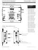
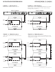
FIGURE 9 – DIP Switches (CNFE200(X)/M Small Size Units Only)
FIGURE 10 - Fault Relay Operation (CNFE200(X) Standard Size Units Only)
The fault relay is normally closed and will open on any of the following alarm conditions:
- Link Fault is enabled on the remote CNFE200(X) unit and a copper port has been disconnected.
- Link Fault is enabled on the local CNFE200(X) unit and a copper port has been disconnected.
- Fiber Fault is enabled on the local CNFE200(X) unit and the fiber link is down or the power has been lost to
either the local or remote CNFE200(X) unit.
SW NAME OFF (DOWN) ON (UP)
1 LINK FAULT ENABLE PORT 1
Link Fault Pass-Through Disabled
Link Fault Pass-Through Enabled.If the Copper Port is Down or Not Connected, the
Optical Port will turn on and off at a ~1 sec rate to indicate copper port 1 fault.
2 LINK FAULT ENABLE PORT 2
Link Fault Pass-Through Disabled
Link Fault Pass-Through Enabled.If the Copper Port is Down or Not Connected, the
Optical Port will turn on and off at a ~1 sec rate to indicate copper port 2 fault.
3 MUX MUX Disabled
Mux Enabled. All Ethernet traffic is diverted from the copper ports to the fiber port,
copper-to-copper traffic will be disabled.
4 DEMUX DEMUX Disabled
DeMux Enabled. When two CNFE200(X) units are connected via fiber and both have DeMux
enabled, traffic from Port 1 will go to Port 1 and traffic from Port 2 will go to Port 2 only,
functioning like two separate media converters over one fiber.