
Installation Manual

INS_CNFE200X[POE] Series_REV– 10/18/14 PAGE 7
© 2015 Communications Networks Corporation. All Rights Reserved. “ComNet” and the “ComNet Logo”
are registered trademarks of Communication Networks, LLC.
3 CORPORATE DRIVE | DANBURY, CT 06810 | USA
T: 203.796.5300 | F: 203.796.5303 | TECH SUPPORT: 1.888.678.9427 | INFO@COMNET.NET
8 TURNBERRY PARK ROAD | GILDERSOME | MORLEY | LEEDS, UK LS27 7LE
T: +44 (0)113 307 6400 | F: +44 (0)113 253 7462 | INFO-EUROPE@COMNET.NET
MECHANICAL INSTALLATION INSTRUCTIONS
INSTALLATION CONSIDERATIONS
This fiber-optic link is supplied as Standalone/Surface Mount and Surface
Mount/Rack Mount modules. Units should be installed in dry locations
protected from extremes of temperature and humidity.
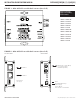
C1-US, C1-EU, C1-AU or C1-CH Card Cage Racks
CAUTION: Although the units are hot-swappable and may be installed
without turning power off to the rack, ComNet recommends that
the power supply be turned off and that the rack power supply is
disconnected from any power source. Note: Remove electrical connector
before installing in card cage rack.
1. Make sure that the card is oriented right side up, and slide it into the card
guides in the rack until the edge connector at the back of the card seats in
the corresponding slot in the rack’s connector panel. Seating may require
thumb pressure on the top and bottom of the card’s front panel.
CAUTION: Take care not to press on any of the LEDs.
2. Tighten the two thumb screws on the card until the front panel of the
card is seated against the front of the rack.
WARNING: Unit is to be used with a Listed Class 2 power supply.
IMPORTANT SAFEGUARDS:
A) Elevated Operating Ambient - If installed in a closed or multi-unit rack
assembly, the operating ambient temperature of the rack environment may
be greater than room ambient. Therefore, consideration should be given to
installing the equipment in an environment compatible with the maximum
ambient temperature (Tma) specified by the manufacturer.
B) Reduced Air Flow - Installation of the equipment in a rack should be such
that the amount of air flow required for safe operation of the equipment is not
compromised.
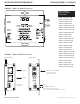
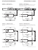
FIGURE B
Dimensions are for a small size ComNet surface mount module
FIGURE A
Dimensions are for a standard ComNet one slot module
.156 [3.96 mm]
.313 [7.95 mm]