
Installation Manual


INS_CWFE100(X) POE SERIES_REVA
08/10/11
PAGE 6
Tech SupporT: 1.888.678.9427
INSTALLATION AND OPERATION MANUAL CWFE100(X) POE SERIES
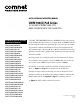
FIGURE 10 – POSSIBLE ETHERNET CONFIGURATION
Remote Ethernet
IEEE802.3at PD
Ethernet IEEE 802.3
Network Element
CWFE1003POEM-M CWFE1003POEM-M
CAT5e/6 with
RJ-45 Connections
CAT5e/6 with
RJ-45 Connections
2 Multimode
Optical Fibers
Ethernet IEEE 802.3 Network Element determined by user.
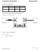
FIGURE 9 – LED INDICATORS
LINK/ACT POE POWER
GREEN
Fiber interface linked
(when lit or flashing)
Power is being
supplied by unit
Unit powered up
OFF
Fiber interface not
linked.
Power not supplied
by unit.
(No PoE device)
Unit powered down
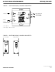
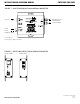
FIGURE 11 – POE PIN ASSIGNMENT
RJ-45 port supports IEEE802.3at
End-point: Positive (VCC+): RJ45 pin 1, 2 or 4, 5
Negative (VCC-): RJ45 pin 3, 6 or 7,8
Data: (1, 2, 3, 6)
30W PoE