
Installation Manual


INS_FDC1-FDC2_REV–
02/21/11
PAGE 4
INSTALLATION AND OPERATION MANUAL FDC1 / FDC2
TECH SUPPORT: 1.888.678.9427
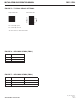
FIGURE 5 – TYPICAL RELAY SETTINGS
FIGURE 6 – LED INDICATORS (FDC1)
FIGURE 7 – LED INDICATORS (FDC2)
CABLE 1
GREEN
Fiber Loop Intact
RED
Fiber Loop Broken
OFF
Unit powered down
CABLE 1 CABLE 2
GREEN
Fiber Loop Intact Fiber Loop Intact
RED
Fiber Loop Broken Fiber Loop Broken
OFF
Unit powered down
Single Channel FDC1 Dual Channel FDC2
1 2
Cable
Contact
NO = Normally Open*
NC = Normally Closed*
* Note: Power On, cable intact state.