
Installation Manual


INS_FDC8ISOT_REV–
03/08/11
PAGE 3
INSTALLATION AND OPERATION MANUAL FDC8NLR
TECH SUPPORT: 1.888.678.9427
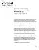
FIGURE 3 – TYPICAL RELAY SETTINGS
RELAY
RELAY
OUTPUT
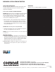
FIGURE 4 – LED INDICATORS
CONTACT (1 – 8) POWER
GREEN
An active signal is present. Unit powered up
RED
No activity –
OFF
Unit powered down
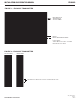
INPUT EQUIVALENT CIRCUIT
1.62K
+
+
–
–
Customer Input:
3mA
DC
– 10mA
DC
5V
DC
– 15V
DC