
Installation Manual


INS_FDX72SHR_REV–
02/29/12
PAGE 3
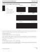
FIGURE 3 – DATA FORMAT SWITCH POSITIONS
TECH SUPPORT: 1.888.678.9427
INSTALLATION AND OPERATION MANUAL FDX72(M,S)1SHR
Switch
Lower bank of switches
located on front panel.
The first two switches set the
data type, the third sets the
Master/Remote Mode.
RS232 Data
1 2 3
RS422, Bi-Phase or
Manchester Data
1 2 3
RS485
4-Wire Data
1 2 3
Remote Mode
1 2 3
RS485 2-Wire, Sensornet
Data
1 2 3
Master Mode
1 2 3
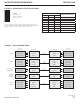
There are two virtual data channels shared between all FDX72SHR units in a system: a Master channel and a Remote channel.
The Master/Remote Mode switch sets the data channel used by the equipment connected to each FDX72SHR unit in the system.
The behavior of a Master and Remote depends on the data type (set by switches 1 and 2):
RS232, RS422, RS485 (4-wire):
Units in Master Mode transmit data to all units set to Remote Mode.
Units in Remote Mode transmit data to all units set to Master Mode.
There is no limit to the number of Masters or Remotes in a system as long as the equipment connected to the FDX72SHR can
handle multiple Masters and multiple Remotes. Most applications requiring Master/Remote communications would use just one
Master and multiple Remotes. Masters can communicate with all Slaves, but not with other Masters. Remotes can communicate
with all Masters, but not with other Remotes.
RS485 (2-wire):
Units in Master Mode transmit data to all units set to Master Mode.
Units in Remote Mode transmit data to all units set to Remote Mode.
The concept of Master and Remote are not used with RS485 (2-wire) mode. Rather, the Master/Remote Mode switch simply sets
which of two independent data channels each unit will use. All Masters can communicate with each other, but not with Remotes.
All Remotes can communicate with each other, but not with Masters.
}