
Installation Manual


INS_FDX72SHR_REV–
02/29/12
PAGE 5
TECH SUPPORT: 1.888.678.9427
INSTALLATION AND OPERATION MANUAL FDX72(M,S)1SHR
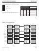
FIGURE 7 – LED INDICATORS
LINK A LINK B DIN DOUT STATUS POWER
GREEN Unit In Sync Unit In Sync Data Activity Data Activity System OK. No Alarm Unit Powered Up
RED Unit Not In Sync Unit Not In Sync – – Fault Detected. Alarm Condition. –
OFF – – No Data Activity No Data Activity – Unit Powered Down
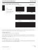
FIGURE 6 – 7-PIN DATA CONNECTOR
BIAS Current limited +5V connection. This terminal can be used as a
connection for pull-up resistors, if required.
ALARM Alarm relay output. Indicates fault conditions. The relay is internally
connected to the GND terminal when no faults are detected (i.e.
a normally closed relay). The relay circuit opens when a fault is
detected anywhere in the system.
GND: Signal ground reference. This terminal can be also be used as a
connection for pull-down resistors, if required.
DIN+/DIN- Electrical data inputs. See Figure 5 for data connections.
DOUT+/DOUT- Electrical data outputs. See Figure 5 for data connections.