
Installation Manual

INS_FDXT1E1_REV–
11/07/12
PAGE 1
INSTALLATION AND OPERATION MANUAL
FDXT1/E1(M,S)1(A,B)
T1/E1 POINT-TO-POINT TRANSCEIVER
FDXT1/E1(M,S)1(A,B)/R3
T1 POINT-TO-POINT TRANSCEIVER
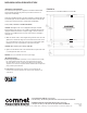
The ComNet™ FDXT1/E1 data transceivers are T1/E1 links that support AMI
and B8ZS data signals over one single mode or multimode optical fiber. The
transceivers synchronize and regenerate data to eliminate jitter accumulated
through the link. Models within this series are available for use with multimode
or single mode optical fiber. Plug-and-play design ensures ease of installation
requiring no electrical or optical adjustments.
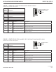
Each transceiver incorporates a bi-color (Red/Green) indicating LED for monitoring
proper system operation. See Figure 6 on Page 5 for an explanation of LED
indications.
The FDXT1/E1 standard size units may be either wall or rack-mounted in a
ComNet card cage, or may be installed in an IFS R3 rack with the selection of the
corresponding model. See Figure A on Page 5 for mounting instructions.
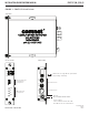
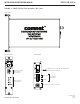
See Figures 1 – 6 for complete installation details.
Please note that the FDXT1/E1/R3 IFS-compatible units support T1 links only.