
Installation Manual

INS_FDXT1E1_REV–
11/07/12
PAGE 4
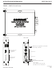
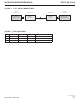
FIGURE 3 – FDXT1/E1 ComFit Unit Data Format Switch Positions
Switches are located on front panel.
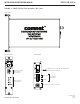
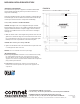
FIGURE 4 – FDXT1/E1/R3 IFS-Compatible “R3” Unit Data Format Switch Positions
Switches are located on front panel.
TECH SUPPORT: 1.888.678.9427
INSTALLATION AND OPERATION MANUAL FDXT1/E1(M,S)1(A,B)
T1/E1
Mode
(Switch 1) Description
On T1 Mode
Off E1 Mode
Format
(Switch 2) Description
On AMI Data Format
Off B8Zs Data Format
Test 0
(Switch 3)
Test 1
(Switch 4) Test Label Description
On On None N/A
Off On Optical Loopback (Analog)
RX Fiber Input to TX Fiber Output Looped Back Internally through
Analog Components
On Off Optical Loopback (Digital)
RX Fiber Input to TX Fiber Output Looped Back Internally through
Digital Components
Off Off Local Loopback (Analog)
Loops Copper Received Data (P1, Pins 1 and 2) to Copper Transmit
(P1, Pins 4 and 5)
Format
(Switch 1) Description
On AMI Data Format
Off B8Zs Data Format
Test 0
(Switch 2)
Test 1
(Switch 3) Test Label Description
On On None N/A
Off On Optical Loopback (Analog)
RX Fiber Input to TX Fiber Output Looped Back Internally through
Analog Components
On Off Optical Loopback (Digital)
RX Fiber Input to TX Fiber Output Looped Back Internally through
Digital Components
Off Off Local Loopback (Analog)
Loops Copper Received Data (P1, Pins 1 and 2) to Copper Transmit
(P1, Pins 4 and 5)
GND
+Vin
PWR
OPTICAL
FDXT1E1
SM
AB
T1/E1 CCITT
TRANSCEIVER
LINK
TX
RX
TEST
ON
1234
E1 IN
E1 OUT
T1
T1/E1 Mode Select
Format Selection
Test 0
Test 1
Format Selection
Test 0
Test 1