
Instruction Manual

INS_NetWave_REV– 06/10/13 PAGE 9
INSTALLATION AND OPERATION MANUAL NETWAvE
TECH SUPPORT: 1.888.678.9427
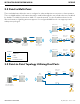
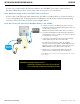
Connect one end of an RJ-45 Ethernet cable to the LAN OUT port of the Power Injection
Module (PIM) and the other end to LAN of the access point – as sown below.
Note: Maximum length of the RJ-45 CAT5 cable is 90 meters.
Connect the RJ-45 Ethernet cable attached to the PIM to a network device, such as a switch or
to the configuration PC. Then plug the power adaptor to an AC power outlet and power plug
into the socket of the PIM – as shown in the diagram below.
Note: DC Passive PoE input for the NetWave Radios is 24 - 48VDC.
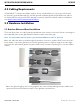
A
D
D
D
B
Ethernet
Network
C
Network
Edge Device
P1 P2
A. Connect one end of an RJ-45 Ethernet cable to the OUT
port of the Power Injection Module (PIM) and the other end
to LAN of the access point.
Maximum length of the RJ-45 CAT5 cable is 100 meters.*
B. Connect the RJ-45 Ethernet cable attached to the PIM to a
network device, such as to a switch or to the PC you will use
to configure the access point.
C. Connect the power adaptor to the main electrical supply
and the power plug into the socket of the PIM.
PoE power input: Passive PoE (range 24 - 48 VDC).
The unit can also be powered by a suitable IEEE 802.3af/at
PSE device such as a PoE switch or injector. Exception: the
NWK11/M Radios only accepts Passive PoE Power.
D. A Drip Loop is recommended as additional precaution
against moisture entering the Access Point housing.
* Up to 200mW radio. For higher power radio upgrade to higher rating
power adapter.
IMPORTANT: Only plug PoE power to Port 1.
Connecting a PoE power source to the PSE Port (#2) will
cause a major device malfunction and void the warranty.