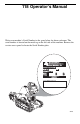
TM COMPACT BIG POWER IN ALL PLACES Part No. 999-823 Serial No.
118 Operator’s Manual Write your machine’s Serial Number in the space below for future reference. The serial number is located on the metal tag on the left side of the machine. Remove the service access panel to locate the Serial Number plate. MANUFACTURED BY: MERTZ MANUFACTURING LLC PONCA CITY, OKLAHOMA, USA DATE OF MANUFACTURE S.N. MODEL NO. ENGINE SERIAL NO. WEIGHT POWER LB KG HP KW COMPACT POWER EQUIPMENT 800-476-9673 cpiequipment.
Boxer Product Warranty WARRANTY AND LIABILITY LIMITATIONS Mertz Manufacturing, LLC warrants each new Compact Utility Trencher manufactured (hereinafter referred to as the equipment) by us to be free from defects in materials and workmanship, for a period of one (1) year or 1000 operational hours, whichever occurs first from the date of delivery.
hereunder, on warranties or otherwise, shall be limited to the cost of repair or replacement of defective parts as herein specified. Further Mertz Manufacturing, LLC's maximum liability hereunder arising from any cause whatsoever, including but not limited to, breach of contract or tort (including negligence), shall not exceed the contract price of the equipment furnished hereunder.
TRACK LIMITED PRORATED WARRANTY POLICY STATEMENT Compact Power Inc provides a limited warranty to the original purchaser that the original tracks used on consumer products sold by Compact Power or its authorized Distributor/Dealer, and manufactured by its subsidiary Mertz Mfg., will be free from defects in material and workmanship for a period of one (1) year after the date of purchase or 400 hours of use, whichever occurs first.
Warranty service must be performed by Compact Power or its authorized Dealer's service representative The following items are not covered by this Track Limited Warranty: Parts that are not genuine original manufacturer service parts are not covered by this warranty. Products which are damaged and sold as salvage units or in an “as is” condition are not covered by this warranty.
Boxer Warranty Registration Dear Customer, Mertz Manufacturing, LLC wishes to thank you for your purchase. We are committed to providing our customers with the finest products and product support available in any market today. To do this, we need to update our database with some specific information. Currently, the warranty start date is listed as the date the Boxer Trencher left Mertz Manufacturing, LLC. This may be several months before you ever received the product.
Affix Stamp Here Mertz Manufacturing, LLC P.O.
Safety Introduction Be Prepared - Get to Know All Operating and Safety Instructions This is the Safety Alert Symbol. Wherever it appears, either in this manual or on safety signs on the machine, you should be alert to the potential for personal injury or accidents. Always observe safety precautions and follow recommended procedures.
viii
Table of Contents Boxer Product Warranty ...................................................................................... i Track Limited Warranty Policy Statement ....................................................... iii Safety Introduction ........................................................................................... vii Be Prepared - Get to Know All Operating and Safety Instructions ......... vii Learn the Signal Words Used with the Safety Alert Symbol...................
Configuring the Chain........................................................................ 4–29 Parts List .................................................................................................. 4–30 Boxer 118 Hydraulic Interconnect Diagram.............................................. 4–32 Section 5 – Troubleshooting .......................................................................... 5–1 Section 6 – General Specifications ...............................................................
Section 1 – Safety Precautions Since Mertz Manufacturing has no direct control over machine application or operation, following the proper safety practices is the responsibility of the owner and/or operator. Remember that this unit is only as safe as those who operate it. Safety tips shown throughout this Operator's Manual must be followed at all times. GENERAL SAFETY • Never operate the Boxer without first completely reading and understanding this Owner's Manual.
Safety Precautions OPERATING SAFETY • Plan ahead and learn as much as possible about your job-site area before beginning any work. • Know the exact location of overhead power lines or obstructions. • Have all buried lines such as; gas, electric, water, telephone and cable TV, marked by the proper authorities. • Prior to use, perform the "Pre-Start Inspection" and Daily Maintenance to make sure that the unit is in safe operating condition.
Safety Precautions • If the unit should begin to tip or become unstable, DO NOT try to stabilize the unit with your legs or arms. • If the unit is involved in an accident or inadvertently damaged during operation, stop and perform a thorough inspection. Make sure the unit is in safe operating condition prior to resuming work. • Be alert to any unusual reaction to any of the controls. If anything unusual is noticed, shut the machine down and thoroughly inspect it to determine the cause of the problem.
Safety Precautions SERVICE & MAINTENANCE SAFETY Maintenance work can be hazardous if not done in a careful manner. All personnel should realize the hazards and strictly follow safe maintenance practices. Failure to comply with these safety precautions may result in serious personal injury and/or death. • Use only BOXER supplied or approved replacement parts. Imitation parts may lead to unit damage and/or injury to personnel. Warranty may be voided if unauthorized parts and are used.
Safety Precautions Battery Hazards Before working with batteries, the following are important points about battery safety that you should be aware of: • Batteries are always surrounded by extremely explosive gases. This is especially true when the battery is being charged. To avoid explosion: – Do not smoke near batteries. – Keep arcs, sparks and open flames away from batteries. – Perform battery service work only in a well ventilated area.
Safety Precautions Hydraulic System Hazards The hydraulic system is under pressure whenever the engine is running and may hold pressure even after the engine is shut off. Cycle all hydraulic controls after the trench boom is resting on the ground. Some components will retain residual or trapped pressure. Use extreme caution when removing any hydraulic component. During inspection of the hydraulic system: • Cycle all hydraulic controls to release residual pressure.
Safety Precautions Fueling Hazards Most fuels are highly flammable. Observe the following precautionary practices to reduce the possibility of a serious accident: • Always refuel the unit in an open, well ventilated area away from sparks or open flames. DANGER Gasoline Engines: • Shut the engine off before attempting to fuel the machine. Never refuel a unit while it is running. • Allow engine to cool before re-fueling • Always use a funnel or pour spout when filling the tanks.
Safety Precautions 1-8
Section 2 – Operating Controls Component Locations Right Front View 1 2 9 3 8 4 5 6 7 Item No.
Operating Controls Left Rear View 1 2 3 8 4 7 6 5 Item No.
Operating Controls Operating Controls 2 3 4 5 6 7 1 8 2424 Item No.
Operating Controls Safety Decals 1 2 11 1 10 3 9 8 4 5 6 7 12 2 8 13 3 6 5 Item No.
Operating Controls Operating Controls Description 5 1 2 3 4 5 6 2425 1. Boom Raise and Lower – This lever controls the raising and lowering of the trencher boom assembly. 2. Left Travel Motor Control – Pushing the lever forward rotates the left side track for forward travel. Pulling the lever backwards rotates the left side track for reverse travel. 3. Right Travel Motor Control – Pushing the lever forward rotates the right side track for forward travel.
Operating Controls 7 8 9 10 2422 7. Engine Choke – Moving the lever to the left sets the choke for easier cold engine starting Moving the lever to the right opens the choke and allows the warmed up engine to run properly. 8. Engine Throttle – Moving the control lever to the left increases the engine speed and moving the lever to the right slows the engine to idle speed. 9. Keyswitch – Starts and stops the engine. 10.
Section 3 – Pre-Start Inspection and Operation DANGER IMPROPER USE OF THE COMPACT TRENCHER COULD CAUSE SERIOUS INJURY OR DEATH. BEFORE OPERATING THE MACHINE, OR PERFORMING MAINTENANCE, THE OPERATOR MUST READ AND UNDERSTAND THE ENTIRE OPERATOR'S MANUAL, REVIEW MACHINE CONTROLS, LOCATE AND REVIEW ALL WARNINGS AND SAFETY PLACARDS AND RELEVANT OPERATOR SAFETY MATERIALS INCLUDING WRITTEN, VISUAL, VIDEO OR VERBAL INSTRUCTIONS.
Pre-Start Inspection and Operation Before starting the engine, do the following pre-start service checks: 1. Check condition of all warning and instructional decals. Replace any damaged decals with genuine BOXER replacement decals. 2. Check engine oil - NOTICE The engine oil dip-stick and engine oil filler port can be reached through the top openings of the front protective cover. • Make sure that the engine is OFF.
Pre-Start Inspection and Operation • If the engine oil level is below the add line, indicated by the letter “A” on the dipstick, carefully add the proper amount of oil through the engine oil filler (Item 3, Figure 3–2). It is important to add the correct type of engine oil as stated in the engine manual. NOTICE • Make sure to reinstall and secure the oil filler cap. • Extremely dusty or dirty working conditions may require more frequent checking, filling and/or changing of engine oil.
Pre-Start Inspection and Operation WARNING Hydraulic oil under pressure can penetrate body tissue causing serious injury and possible death. When troubleshooting a hydraulic system for leaks, always use cardboard or wood as a detector. DO NOT USE YOUR BARE HANDS. If you are injected with hydraulic oil or any other fluids, immediately seek treatment by a doctor trained in the treatment of penetrating fluid injuries.
Pre-Start Inspection and Operation 8. Grease pivot shafts with proper type of grease. There are 5 grease points on this machine, see Figure 3–4. NOTICE The grease zerk below the chain tension bolt should only be greased monthly.
Pre-Start Inspection and Operation CAUTION Before starting the engine: • Move all hydraulic control levers forward and release the lever. Make sure that each lever automatically returns to the Neutral position. • Move all hydraulic control levers rearward and release the lever. Make sure that each lever automatically returns to the Neutral position. • Step on the operator presence control and shift the Trencher Control Lever to the right into the trenching position.
Pre-Start Inspection and Operation Operating Instructions Machine Start-up To start the machine, the operator must: 1. Stand on the operator's platform (Item 1, Figure 3–5). 2. Move the throttle lever (Item 2, Figure 3–5) to about half way between fast and idle engine speeds. 3. Move the engine choke lever (Item 3, Figure 3–5) to the CHOKE position. 4. Rotate and hold the starter switch (Item 4, Figure 3–5) in the START position until the engine starts.
Pre-Start Inspection and Operation WARNING In extremely cold weather fully warm machine to prevent a possible machine run-away condition. Machine Shut-down To safely shut the machine down, the operator must: 1. Park the machine on a solid, level area. 2. Lower the trencher boom to the ground. 3. Idle the engine for 5 - 10 minutes to allow the machine to cool down. 4. Shut off the engine. 5. Clean off any accumulated mud and/or dirt from the machines operating surfaces, i.e.
Pre-Start Inspection and Operation 3. When the machine is positioned on the trailer properly, lower the boom to the trailer deck. 4. Shut the engine off and remove the key. 5. Secure the unit to the transport vehicle with DOT (Department of Transportation) approved chains, binders (Items 1 and 2, Figure 3–6), and DOT guidelines. Make sure to use the appropriate tie-down locations on the machine and trailer. NOTICE • Never tow or pull the machine. Damage to the hydraulic motors could result.
Pre-Start Inspection and Operation 1 2 3 2 4 2435 Figure 3–7 Machine Lifting Machine Travel Controls WARNING • Levers and controls should return to the neutral position when they are released. • Make sure that all of the controls are in the neutral (middle) position before starting the engine. • Operate the controls gradually and smoothly. Excessive speed and quick control movements without regard for working conditions could cause an unsafe situation.
Pre-Start Inspection and Operation The “cogging” condition is most likely to occur while operating in a forward direction pulling a heavy load, and during the first 50 hours of track usage. It is caused by the tension spring being fully compressed due to high track load. If a cogging condition occurs, immediately stop machine travel and machine functions and reverse travel direction slightly to de-compress track tension.
Pre-Start Inspection and Operation Right Turn During Forward Travel Left Turn During Forward Travel To turn to the right, move the left hand control lever farther forward than the right control lever. The farther forward the left control is moved, the faster the right turn will be made. See Figure 3–10. To turn to the left, move the right hand control lever farther forward than the left control lever. The farther forward the right control is moved, the faster the left turn will be made. See Figure 3–11.
Pre-Start Inspection and Operation Spin Turn CAUTION Make sure to use the machine hand holds while doing a spin turn to maintain your balance. Move the travel control levers in opposite directions to spin the machine on it axis. To spin left, move the right control lever forward while pulling the left control lever backwards; to spin turn to the right, push the left control lever forwards and while pulling the right control lever backwards. Figure 3–14.
Pre-Start Inspection and Operation WARNING • Do not travel up or across a slope steeper than 15°. See Figure 3–15. • Keep boom as low as possible when traveling on slopes or rough terrain. >15° 16 15° P 2437 Figure 3–15 Slide Slope Travel • Keep the heavy end of the machine towards the uphill direction when traveling up or down a slope. See Figure 3–16.
Pre-Start Inspection and Operation Operating Instructions WARNING BEFORE BEGINNING ANY TRENCHING, MAKE SURE THAT THE WORK AREA HAS BEEN INSPECTED AND MARKED FOR UNDERGROUND UTILITIES OR POTENTIAL OBSTRUCTIONS. ANY CONTACT WITH UNDERGROUND UTILITIES CAN POTENTIALLY CAUSE INJURY OR DEATH. CONTACT DIGGERS HOTLINE (1-800-242-8511) TO HAVE THE WORK AREA INSPECTED AND MARKED.
Pre-Start Inspection and Operation 1 2441 Figure 3–17 Trencher Boom in Raised Position 3. Depress (step on) and hold the operator presence control (Item 1, Figure 3–18) in the “down” or activated position with your right foot.
Pre-Start Inspection and Operation 4. With your right hand, move the trencher control lever (Item 1, Figure 3–19) to the right to activate the trencher chain in the FORWARD motion. NOTICE The control will remain in the forward position until you either move the lever into the Neutral position or step off the operator presence control. 1 2440 Figure 3–19 Trencher Chain Control Lever in Forward Position 5.
Pre-Start Inspection and Operation 6. When the trencher boom (Item 1, Figure 3–21) has reached the proper digging depth the rock shield (Item 2, Figure 3–21) and spoils auger (Item 3, Figure 3–21) will direct the dirt that has been removed from the trench away from the machine. 2 1 2443 3 Figure 3–21 Trencher at Proper Depth 7. SLOWLY move (feather) the travel control levers rearwards to move the trencher backwards. CAUTION • DO NOT travel backwards too fast. The trencher could become unstable.
Pre-Start Inspection and Operation 10. When all trenching has been completed, raise the trencher boom out of the trench and move the trencher out of the way. NOTICE When the trenching has been completed, move the engine throttle to the idle position and allow the engine to cool off at idle for 3 - 4 minutes. 11. Lower the trencher boom to the ground. 12. Shut off the engine and clean the trencher chain, tracks, and operator's platform of dirt and mud.
Pre-Start Inspection and Operation 3-20
Section 4 – Routine Service and Maintenance The following information presents the routine service and maintenance required to make sure that the machine functions safely and properly. More detailed service information is contained in the Service Manual.
Routine Service and Maintenance Daily Maintenance Procedures Before starting the engine, do the following pre-start service checks: 1. Check condition of all warning and instructional decals. Replace any damaged decals with genuine BOXER replacement decals. NOTICE: Make sure to read and understand all WARNING and SAFETY decals before operating the machine. 2. Check engine oil NOTICE The engine oil dip-stick and engine oil filler port can be reached through the top openings of the front protective cover.
Routine Service and Maintenance c. If the engine oil level is below the add line, indicated by the letter “A” on the dipstick, carefully add the proper amount of oil through the engine oil filler (Item 3, Figure 4–1). It is important to add the correct type of engine oil as stated in the engine manual. NOTICE • Make sure to reinstall and secure the oil filler cap. • Extremely dusty or dirty working conditions may require more frequent checking, filling and/or changing of engine oil.
Routine Service and Maintenance 4. Check Air Filter a. Reach underneath the control panel plate to access the top of the engine. b. Remove the air filter cover (Item 1, Figure 4–3) and inspect the outer air filter sleeve (Item 4, Figure 4–3). The outer air filter sleeve will trap only the largest dirt particles. Remove the air filter sleeve and clean as needed. c. If the sleeve is dirty, loosen and remove the wing nut (Item 2, Figure 4–3) holding the air filter top plate (Item 3, Figure 4–3). d.
Routine Service and Maintenance 3 2 1 4 2051 Figure 4–4 Hydraulic Hose Damage 1. 2. 3. 4. End fittings damaged or leaking Outer covering chafed or cut, and wire reinforcing is exposed Hose shows signs of kinking or crushing Outer covering ballooning 6. Check for loose or missing fasteners a. Inspect for any loose or missing bolts. b. Tighten or replace any missing bolts immediately. 7.
Routine Service and Maintenance 2423 Figure 4–5 Grease Zerk Locations 10. Check for proper track tension. a. Remove the track adjusting wrench (Item 2, Figure 4–6) from the right track assembly. Make sure that the rubber grommets remain on the threaded studs (Item 3, Figure 4–6).
Routine Service and Maintenance b. Place a solid object, such as a concrete block or 8" H x 8" W x 48" L piece of lumber, under the operator's platform. c. Tilt the trencher boom downwards until the lowest cutting edge is touching the ground. See Figure 4-6. d. Continue to lower the boom assembly, pushing the front of the machine upwards. Continue raising the machine until the front drive sprocket and rear idler rollers are off the ground. Shut off the engine. e.
Routine Service and Maintenance CAUTION Before starting the engine: • Move all hydraulic control levers forward and release the lever. Make sure that each lever automatically returns to the Neutral position. • Move all hydraulic control levers rearward and release the lever. Make sure that each lever automatically returns to the Neutral position. • Step on the trencher operator presence control and shift the Trencher Control Lever to the right into the trenching position.
Routine Service and Maintenance 3. Change the hydraulic filter. See Service Manual and Figure 4–9. CAUTION • The hydraulic filter will be filled with hydraulic fluid. Make sure to dispose of the used hydraulic filter in an appropriate manner and according to State and Local regulations. • Make sure to dispose of the used hydraulic fluid in an appropriate manner and according to State and Local regulations. • Place a container under the upper hydraulic tank to capture any hydraulic fluid that may drain out.
Routine Service and Maintenance c. Start and run the engine for about 30 seconds. Using the hydraulic oil level dip stick (Item 1, Figure 4–10), check the hydraulic oil level. Add the appropriate hydraulic fluid as needed through the filler port (Item 2, Figure 4–10) on top of the upper hydraulic oil tank (Item 3, Figure 4–10).
Routine Service and Maintenance Weekly Maintenance Procedures Do the following procedures weekly or every 50 operating hours: 1. Do all Daily maintenance procedures Check the battery (Item 3, Figure 4–11) and cable connections (Items 1 and 2, Figure 4–11) for signs of leaking, corrosion or damage. To complete this check, remove the service access panel. NOTICE Make sure that the battery clamp (Item 4, Figure 4–11) is securely holding the battery in position.
Routine Service and Maintenance Monthly Maintenance Procedures Do the following procedures monthly or every 200 operating hours: 1. Do all Daily and Weekly maintenance procedures 2. Replace engine oil and engine oil filter - see engine manual 3. Replace air Filter. a. Reach underneath the control panel plate to access the top of the engine. b. Remove the air filter cover (Item 1, Figure 4–12) and the outer air filter sleeve (Item 4, Figure 4–12). c.
Routine Service and Maintenance 4. Replace fuel filter. DANGER • GASOLINE IS VERY FLAMMABLE. HANDLE WITH EXTREME CAUTION. • MAKE SURE THAT THE ENGINE HAS BEEN ALLOWED TO COOL BEFORE PERFORMING THIS OPERATION. • MAKE SURE THAT THERE ARE NO OPEN FLAMES IN THE WORK AREA. • ONLY PERFORM THIS PROCEDURE IN AN AREA WITH PROPER VENTILATION. • DO NOT SMOKE WHILE PERFORMING THIS OPERATION. • CLEAN UP ANY SPILLED FUEL BEFORE STARTING THE ENGINE. a.
Routine Service and Maintenance 2 3 1 3 2451 Figure 4–13 Fuel Filter Replacement CAUTION Make sure to clean up any spilled fuel from in and around the engine compartment of the machine. Spilled fuel may be ignited by a hot engine. 5. Check battery signs of leakage or for corrosion on the battery cables. • On a monthly basis, check the battery (Item 8, Figure 4–14) for signs of leaking electrolyte. If any signs of damage are visible, remove and replace the battery.
Routine Service and Maintenance 10. Loosen the cable clamps and remove the cable from the battery. Clean the terminals with a battery brush. Reinstall and secure the cable clamps. 11. Check the battery hold down clamp (Items 4 and 7, Figure 4–14) to make sure that the battery is being held securely to the machine. NOTICE If the battery needs to be replaced, make sure to dispose of the old battery according to local regulations.
Routine Service and Maintenance Annual Maintenance Procedures Do the following procedures annually: 1. Do all Daily, Weekly and Monthly maintenance procedures 2. Replace air filter. See page 4-12, Step 3. 3. Check engine idle speed (Refer to engine manual) 4. Replace hydraulic fluid. a. Place a suitable sized container at the left front corner of the Boxer. b. Remove the hydraulic tank drain plug (Item 1, Figure 4–15) and drain all hydraulic fluid from the machine.
Routine Service and Maintenance d. Replace hydraulic filter. See page 4-9, Step 3. NOTICE The hydraulic dipstick is located underneath the hydraulic filler cap, located on top of the upper hydraulic tank. See Figure 4–16. e. Unscrew the dipstick assembly and remove from the machine. (1, Figure 4–16) and fill the hydraulic tank with the proper hydraulic fluid (Chevron Rykon Premium ISO 46 or equivalent) until the fluid level is at but not above the upper marker hole in the dipstick.
Routine Service and Maintenance General Maintenance Draining Fuel Tank DANGER 1. GASOLINE IS EXTREMELY FLAMMABLE AND HIGHLY EXPLOSIVE. 2) A FIRE OR EXPLOSION FROM GASOLINE CAN BURN YOU OR OTHERS AND CAUSE PROPERTY DAMAGE. 3) DRAIN FUEL FROM TANKS WHEN THE ENGINE IS COLD. 4) FUEL TANKS SHOULD ONLY BE DRAINED IN AN AREA THAT IS WELL VENTILATED. 5. WIPE UP ANY GASOLINE THAT SPILLS. 1. Park the machine on a level surface, to make sure that the fuel tank is completely drained. 2.
Routine Service and Maintenance 5. Loosen the lower intake hose clamp (Item 3, Figure 4–17) at the fuel filter (Item 2, Figure 4– 17). Slide the clamp along the fuel line (Item 3, Figure 4–17), away from the filter. 6. Pull the fuel line off of the fuel filter and position the line in a suitable sized container. NOTICE The fuel tank holds approximately 3 gallons of fuel. 7. Open the fuel valve (Item 1, Figure 4–17) and allow the fuel to drain into the drain container. 8.
Routine Service and Maintenance Adjusting Digging Chain Tension Adjust the digging chain tension every 25 operating hours. With the trencher parallel to the ground, make sure that there is 1¾" to 2" of chain sag between the bottom of the boom and the top of the bottom chain span. See Figure 4–18. NOTICE • For a new chain, check the chain sag after the first hour of operation. • Depending on working conditions, chain sag adjustments may need to be done more frequently.
Routine Service and Maintenance If the chain tension needs to be adjusted: 1. Loosen the adjustment bolt lock nut (Item 2, Figure 4–19) 2. Rotate the chain adjustment bolt (Item 3, Figure 4–19) to increase or decrease pressure on the boom until the proper chain sag is measured. 3. Tighten the adjustment bolt lock nut. 4. On a monthly basis, lubricate the adjustment bolt using the grease zerk (Item 1, Figure 4–19).
Routine Service and Maintenance Trencher Boom Replacement Adjust the digging chain tension every 25 operating hours. With the trencher parallel to the ground, make that there is 1¾" to 2" of chain sag between the bottom of the boom and the top of the bottom chain span. See Figure 4–20. NOTICE For this procedure, raise the trencher off the ground a short distance to make working on it easier. CAUTION Make sure to shut off the machines engine and remove the key from the ignition.
Routine Service and Maintenance 10.
Routine Service and Maintenance Replacing the Digging Teeth Due to the high amount of wear placed on the digging teeth, you will need to replace them periodically. To replace a single tooth (Items 3 and 5, Figure 4–20), remove the bolts and nuts (Item 1 and 2, Figure 4–21) securing the tooth to remove it, and then install a new tooth in the same position. NOTICE The spacer tubes (Item 4, Figure 4–21) will fall free. Make sure to reinstall these when the new tooth is installed.
Routine Service and Maintenance Replacing the Drive Sprocket Overtime, the drive sprocket will wear, especially when used in sandy or clay soils. When this happens, the digging chain will begin to slip. If the chain slips, replace the drive sprocket, as follows: 1. Raise the trencher a few inches above the ground. 2. Stop the engine and remove the key. 3. Remove the spoils auger (Item 1, Figure 4–22). 4.
Routine Service and Maintenance 10. Install the spoils auger and secure it using the nut removed earlier. 11. Set the upper span of the chain into place on the trencher boom, and then wrap the chain around the roller at the end of the boom. Connect the chain together as shown in the “Chain Master Link” on page 28 for instructions. 12. Tighten the chain tension adjustment bolt until the proper chain tension is set according to the Adjusting Digging Chain Tension instructions shown earlier in this section.
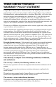
Routine Service and Maintenance Chain Configuration You can set up the chain in different configurations, depending on the width of the trench desired and the soil conditions at the work site. Depending on the size of boom you purchased, you will either have a chain with: • 24 links (24 inch [60.9 cm] boom) • 32 links (36 inch [91.4 cm] boom) Each link can have digging teeth fastened to it and are referred to as a station.
Routine Service and Maintenance Chain Master Link If the trencher chain needs to be removed from the trencher, it can be broken at the Master Link. CAUTION When the Master Link is removed, the chain could fall off the trencher frame. Keep your hands and feet from underneath the chain to prevent injury. To separate the Master Link: 1. Inspect the chain and locate the master link (Item 1, Figure 4–24), which will have a removable pivot pin and cotter pin instead of two bolts. 2.
Routine Service and Maintenance Configuring the Chain To configure the chain, complete the following procedures: Select the chain configuration you want to install from the chain configuration illustrations (Configurations A - E, Figure 4–22) and obtain all necessary parts. 1. Lower the trencher boom, stop the engine, and remove the key. 2. Remove the unneeded teeth and other hardware from the links on the top span of the chain.
Routine Service and Maintenance Parts List Trencher Chain Parts list Item # 1 2 3 4 6 8 9 10 11 12 13 14 15 16 17 4-30 Description BOLT, 3/8"-24 X 2 1/4 BOLT, 3/8"-24 X 2 3/4 BOLT, 3/8"-24 X 3 BOLT, 3/8"-24 X 2 1/2 BOLT, 3/8"-24 X 3 3/4 LOCK NUT FLAT WASHER SPACER TUBE, 1 3/8 LEFT TERMINATOR TOOTH RIGHT TERMINATOR TOOTH LEFT CUP TOOTH RIGHT CUP TOOTH SPACER TUBE, 1 1/4 FLAT SPACER FLAT SPACER Quantity "12 "24 "8 "12 "8 64 16 "52 8 8 8 8 "12 4 4 Part # 38242148 38242348 382438 38242128 38243348 3824 382
Routine Service and Maintenance 13 12 10 10 11 14 8 8 9 2 Configuration D 4 Configuration A 12 14 10 15 11 8 16 1 13 9 8 Configuration B 14 6 Configuration E 10 13 8 17 3 Configuration C 2303-2 Figure 4–25 Chain Configuration 4-31
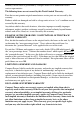
Routine Service and Maintenance Boxer 118 Hydraulic Interconnect Diagram CONTROL VALVE VENT AUX. VALVE FILTER, IN TANK RETURN TO TANK MOTOR RIGHT TRENCHER MOTOR TOP TOP PUMP SUCTION FROM TANK MOTOR LEFT TILT CYL.
Section 5 – Troubleshooting The following procedures will assist you in determining the potential cause of a machine operating problem. Problem Possible Causes Starter does not turn the engine over. • Trencher control lever is either in Forward or Reverse position and the operator presence control is depressed. • Move lever to neutral position. • Release operator presence control. • Battery is dead. • Charge the battery. • If battery does not hold a charge, replace the battery.
Troubleshooting Problem Engine looses power. Engine overheats. Possible Causes Corrective Action • Engine load is excessive. • Reduce ground speed. • Reduce speed of trencher. • Air cleaner is dirty. • Clean air filter housing and replace the filter elements. • Engine oil level in crankcase is low. • Add the appropriate engine oil to crankcase. See engine manual for oil specifications. • Cooling fins and air passages under engine blower housing are plugged.
Troubleshooting Problem Possible Causes • Engine is not running at full The machine does not speed. travel in either forward or reverse directions. • Hydraulic fluid is cold. Trencher chain does not turn • Advance throttle to full engine speed. • Fully warm hydraulic fluid. • Hydraulic fluid level is low. • Check and fill the hydraulic fluid tank with the appropriate hydraulic fluid. • Fuel tank is empty and engine stops. • Fill fuel tank with fuel. • If all above has been checked.
Troubleshooting 5-4
Section 6 – General Specifications Engine System Type Cooling System HP / KW Fuel Tank Air Cleaner Hydraulic System Reservoir Capacity Filter Electrical System Battery Control System Starting Throttle/Choke Steering Warranty Engine Warranty Product Warranty Ground Drive System-Dimensions Units Trench Depth Trench width Boom travel up Boom travel down Length (Boom Travel Position) Width Height Wheel Base Ground Speed Forward Ground Speed Reverse Chain Speed Trench center to outside left Trench center to out
General Specifications Noise Data Tests were performed in accordance with EU Machinery Directive 98/37/EC EN 474-10:2006 in addition to ISO/DIS 6394:2004. Engine RPM was @ 3600 rpm (max) rpm. The noise measurements were made with the operator present. The declared value for the operator is 77 dB (LA). The Guaranteed SWL value is 107 dB (LWA).
FOLD ALO NG D THIS OTTE IS A D LIN 15 D E EGR EE S LOP E DO NOT TRAVEL ACROSS OR UP AND DOWN A SLOPE GREATER THAN 15 DEGREES. SUGGESTED GUIDE FOR SIGHTING SLOPES FOR SAFE OPERATION OF A COMPACT UTILITY LOADER WITH AN ATTACHMENT. DO NOT REMOVE THIS PAGE FROM THE MANUAL. 16 15 DEGREES MAX. THIS IS A 15 DEGRE E SLOPE DO NOT TRAVEL ACROSS OR UP AND DOWN A SLOPE GREATER THAN 15 DEGREES WARNING 16 To avoid serious injury, operate your unit up and down the face of slopes.
Compact Power Inc. P.O. Box 40 – Fort Mill, SC 29716 Phone: 800-476-9673 – Fax: 803-548-2762 Web Site: http://www.cpiequipment.