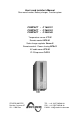
User’s and installer’s Manual Sine wave Inverter, Battery charger, Transfersystem COMPACT - C 1600-12 COMPACT - C 2600-24 COMPACT - C 4000-48 Temperature sensor CT-35 Remote control RCC-01 Solar charge regulator Cxxxx-S Remote control - Power sharing RPS-01 AC cable cover CFC-01 IP-23 top cover C-IP23 STUDER INNOTEC Rue des Casernes 57 CH – 1950 Sion TEL : ++41 (0)27 205 60 80 FAX : ++41 (0)27 205 60 88 E-MAIL : info@studer-innotec.
STUDER Innotec COMPACT English description .................................................................................................................. 5 1 General Information......................................................................................... 5 1.1 Operating instructions ........................................................................................ 5 1.2 Quality and Warranty ......................................................................................... 5 1.
STUDER Innotec COMPACT English description 1 General Information 1.1 Operating instructions This manual is part of the delivery package of every COMPACT inverter-charger. It serves as guidelines for safe and efficient operation of COMPACT.
STUDER Innotec 1.4 COMPACT Liability Disclaimer Respecting this manual, servicing and method of installation, functioning, application and maintenance of the appliance can not be controlled or supervised by STUDER INNOTEC.
STUDER Innotec COMPACT − Plenty of fresh water and soap must be ready at hand so that in case of acid coming in contact with skin, eyes and clothes, the areas in question can be thoroughly washed. − If acid enters the eyes, you must thoroughly wash them with cold running water for at least 15 minutes. It is recommended that you immediately consult a medical doctor. − Baking powder neutralizes battery acid electrolyte. Always keep some at hand.
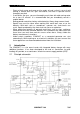
STUDER Innotec COMPACT Notes: (1) The neutral of the appliance is not connected to the earth whatever the function mode is. If requested and according to the local regulation, an automatic connection between Neutral and earth in inverter mode only may be done by installing a bridge internally to the unit. Please contact your installer regarding this point. (2) Remote control for remote adjustment of the input limit. (see chap. 4.6.3) 2.2 Description of the main functions 2.2.
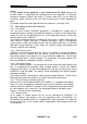
STUDER Innotec COMPACT 2.2.6 Remote control for Power Sharing This remote control RPS-01 can be connected to the COMPACT in the dedicated plug. The maximum current available from the energy source can be adjusted by the turning button. 2.3 Battery connecting Lead-acid batteries are normally available in blocks of 2V, 6V or 12V.
STUDER Innotec COMPACT 2.3.3 Serial and parallel connection 3 Mounting and installing 3.1 Installation place The location of the COMPACT must be driven by the following criteria: − Protection from unauthorized handling − Dry dust free room, no condensation − Never install directly over the battery and never in a cabinet together with the batteries − Keep ventilation holes free − In mobile installations it is important to keep the vibrations down as low as possible 3.2 Fixing 3.2.
STUDER Innotec COMPACT − To protect the battery cable, a fuse corresponding to the conductor cross section must be fixed directly on to the battery. − All cables must be tightly screwed in place. For safety, a yearly control is recommended. In mobile installations control must be carried out more often. − Connecting must be done by qualified personnel. Material such as cable, connectors and distribution boxes, fuses etc.
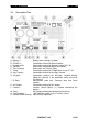
STUDER Innotec 3.4 A B C D E F G H J K L M N O COMPACT Connection Plan Battery +/SOLAR +/Remote contr. Equalize Transfer delay Temp. Aux. Contact AC Input Battery cable (already installed) Connection terminal for Solar modules Connection terminal for Remote Control RCC-01 Slide switch for equalization of the Battery Slide switch for Transfer Delay Connection terminal for Temperature sensor CT-35 Connection terminal for Auxiliary Contact Connection terminal for AC-input.
STUDER Innotec 3.5 COMPACT Cabling Connecting the COMPACT is a very important step of the installation. You must take care that all connection work is carried out in a clean and correct way and that under no circumstance a cable is connected to a wrong terminal. Connecting of the COMPACT must be carried out in the following order. In case of dismantling this order must be reversed. 3.6 Pre-installation settings Before you start with the cabling of the COMPACT you must set the type of battery.
STUDER Innotec COMPACT 3.6.4 Connect the solar modules: SOLAR +/- (Only for solar option) Solar modules are connected on these terminals. Under no circumstances should any other energy source i.e. wind generator be connected to these terminals! Only solar modules must be connected with two cables +/-. Depending on the power of the modules, the cable cross section should be 2.5 up to 6mm2.
STUDER Innotec COMPACT 4 Control 4.1 Display and control parameters COMPACT V6.
STUDER Innotec 4.2 COMPACT Light Emitting Diodes (LED) LED 1 Marking AC IN 2 CHARGER 3 SOLAR CHARGE 4 Program 5 6 Contact active Contact manual 7 TRANSFER 8 AC OUT 9 INVERTER 10 Over Temp. 11 Overload 12 Batt. Low/High 13 OFF 14 EQUALIZE 15–18 LED lit Voltage corresponding to self-adjusted values is at the AC IN input. Battery charger is working Connected solar modules are delivering energy Program mode for Aux. Contact Auxiliary Contact is activated Aux. Cont.
STUDER Innotec 25 4.3 19 20 21 4.4 22 23 24 26 4.5 POWER MONITOR COMPACT Display the value of the output power in % of Pnom (in Inverter Mode) and the charge current in Amps (in Charger Mode). In this mode the red LED indicates that power sharing is in use (>100A). Push buttons Turning the COMPACT on and off (Help Button for Programming) RESET Alarm Signal off (Help Button for Programming) Aux. Contact Control Aux.
STUDER Innotec COMPACT time, then it no longer switches on automatically. The LED 13 remains lit. Press the push button 19 „ON/OFF“ in order to switch on the Inverter. 4.5.3 Overheating (Over Temp.) If the Inverter has been overloaded for a long time or it has been working in too high surrounding temperatures, it will switch off. The LED 10 „Over Temp.“ is lit and the LED 13 „OFF“ blinks. After cooling down, the inverter switches back on automatically.
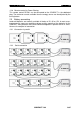
STUDER Innotec 4.6 COMPACT The battery charger 4.6.1 Cycle of charge The full automatic COMPACT Battery Charger is adjusted at the factory so that most lead-acid and lead-gel batteries can be charged to the maximum. As soon as the minimum alternating voltage for the AC IN set on the Turning Knob 23 is available at the input (LED 1 AC IN is lit), the Battery Charger is switched on automatically (LED 2 CHARGER is lit).
STUDER Innotec COMPACT from “OFF” to the “ON” position. The LED 14 will light up. If the periodic equalization is not required, slide switch must be slid back to the „OFF“ position after the completion of the manual cycle. The equalizing voltage can be changed. How to proceed is explained in chap. 5.3. Batteries not designed for equalize should never been charged this way. CAUTION: During the equalization process, the batteries produce a lot more gas.
STUDER Innotec COMPACT state of charge is displayed accurately.
STUDER Innotec COMPACT 4.7.1 Set the transfer voltage threshold The voltage threshold of the transfer can be adjusted between 150 to 230V with the turning knobs (23). From factory this value is 200V. Most appliances can work on this voltage. When the Input voltages reach the selected value on turning knob, the inverter switches off and the AC INPUT goes directly on the AC OUTPUT. When the voltage INPUT is less of 20V the value set, the transfer is stopped and the OUTPUT switches back on the inverter.
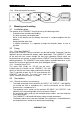
STUDER Innotec 4.9 COMPACT The Multifunctional Contact In the COMPACT there is a built-in programmable power relay. The potential-free change-over contact (NO – NC) of this power relay is connected to the screw terminal AUX CONTACT. Maximum Contact load: 230Vac / 12Vdc / 24Vdc / 16A ! > 36Vdc / 3A ! With the Push Button 21 „AUXILIARY CONTACT“ the contact can be manually switched on or off independently from programming and from the operating situation.
STUDER Innotec COMPACT Auxiliary Contact of the COMPACT. This con-tact is active in case of an alarm of the COMPACT. The Control Input is connected in parallel to the ON/OFFpush button. The COMPACT can be switched on or off through this input with an impulse button or an impulse contact. Caution: No external voltage should be connected to this Input Control. Order Number for Remote Control: RCC-01 Dimensions: H x B x T / 111.5 x 136.5 x 25mm 4.
STUDER Innotec 5 COMPACT Programming The COMPACT (except for 60Hz versions) is equipped with a Flash processor fitted out with EEPROM Memory, which means that even when it is disconnected from the battery, the parameters that were programmed for the application remain after a new connection to the battery. It is possible to reinitialize (RESET) the COMPACT by pressing simultaneously on the three push buttons 19/20/21 during at least 2 seconds. A beep will confirm the RESET.
STUDER Innotec COMPACT With the Push Button 19 (Change status) set the desired parameter (voltage or time) to modify (LED 14/ 15/16/17/18). Push Button 19 (Change status) to set the desired value according to the table 5.3.2. If desired, repeat the operation with any other parameter (voltage or time) to be changed. If during 30 seconds no buttons are pressed, the selected values are automatically stored and the COMPACT switches back in to the normal operating status.
STUDER Innotec COMPACT are automatically stored and the COMPACT switches back to normal operating condition. 5.4.3 Auxiliary Contact as generator starter As per the battery capacity When in the programming of the Auxiliary Contact, the Battery Capacity (LED 15-18) is used as a condition, you must then take note of the following requirements. If you have to start an emergency back-up supply with a battery having a certain residual capacity, then two battery levels must be programmed. The first (i.e.
STUDER Innotec COMPACT Programming must be carried out in steps and in accordance with the description for the programming of the Auxiliary Contact. 5.4.5 Power cut of the second priority loads The auxiliary contact can also be used to cut the power of less priority loads when the battery state of charge is lower than a given threshold. In that case, only one of the battery state of charge, or the “transfer” function will be programmed as power cut criteria.
STUDER Innotec 6 COMPACT Installation Maintenance Apart from the periodic controls mentioned for the connections, the COMPACT does need any maintenance. Keep the appliance clean and from time to time, wipe it clean with a damp cloth. 7 Declaration of CE Compliance Hereby we state that the products described in this user manual comply with the following standards: EN 61000-6-1, EN 61000-6-3, EN 55014, EN 55022, EN 61000-3-2, Dir. 89/336/EEC, LVD 73/23/EEC, EN 50091-2, EN 60950-1.
STUDER Innotec 8 COMPACT Technical Data COMPACT V6.