
User manual


CompAir BroomWade Limited
page 12
GENERAL DESCRIPTION
1. COMPRESSOR
The unit is a fully enclosed, air cooled, single-
stage, rotary screw compressor. The compressor
air-end is belt driven by an electric squirrel-cage
induction motor. The drive belts are mounted on
pulleys fitted to the shafts of the drive motor and
air-end.
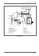
The compressor unit consists of the drive motor,
air-end, oil separator vessel, oil separator filter, oil
cooler, aftercooler, cooling fan, starter assembly
and controller.
The complete compressor unit is mounted on a
baseframe and is housed in a steel panelled
acoustic enclosure. A service panel allows access
for routine maintenance.
2. AIR-END (CYCLON 3)
The air is compressed in a single-stage, positive
displacement, oil injected rotary screw air-end. The
air-end is of the Cyclon type and comprises an
intermeshing pair of helical screw rotors, male and
female, mounted horizontally within an enclosed
casing with drive being applied to the male rotor.
The male rotor in the Cyclon air-end is larger in
diameter than the female rotor and has four lobes
which mesh with five flutes on the female rotor. The
rotors are asymmetric in profile to reduce blowback
between the lobes on the compression cycle to a
minimum, thus maximising overall sealing and
efficiency.
The rotors are fitted with bearings at each end to
provide radial and axial support, maintain adequate
shaft stiffness and to give minimum clearance and
low leakage between the rotor tip diameter and the
casing.
At the delivery end the male rotor is fitted with a
single taper roller bearing and the female rotor has
a pair of matched taper roller bearings. These
bearings provide axial and radial support of both
rotors and control the very fine end clearances
between the rotors and the casing.
Heavy duty parallel roller bearings are fitted to both
rotors at the inlet end to provide radial support and
to sustain the drive load of the male rotor.
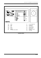
3. ELECTRONIC CONTROLLER
The electronic control system is microprocessor
based with an LED display panel, incorporating
advanced control and monitoring features.
4. PROTECTION AND SAFETY EQUIPMENT
In addition to the protection and warning circuits
linked to the control panel the following protection
devices are fitted:
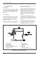
4.1 Relief Valve
A pressure relief valve is mounted on the primary
oil separator. If pressure continues to build up
when the demand for compressed air has ceased,
the relief valve will open at a pre-set level to
discharge the excess pressure to atmosphere.
4.2 Blowdown System
Whenever the compressor shuts down, either
automatically or by operation of a ‘STOP’ switch, all
pressure in the oil separator vessel is automatically
released by a blowdown system which vents the
pressure to atmosphere. This ensures that the
compressor is restarted in a no-load condition.
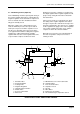
4.3 Minimum Pressure/Non-return Valve
Fitted on the filter manifold, the minimum pressure
valve remains closed until minimum pressure is
reached. This ensures a rapid build-up of pressure
when the compressor first starts and also prevents
high velocity, low pressure air reaching the user’s
pipework during the start-up period and carrying
over excessive amounts of oil.
When the compressor shuts down the non-return
valve prevents the pressure in the user’s pipework
feeding back into the oil separator and venting
through the blowdown system.