
User manual


CompAir BroomWade Limited
page 14
5. AIR/OIL SYSTEM
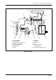
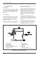
5.1 Description
The air/oil system comprises an air intake filter,
suction regulator, air-end, oil separator vessel, oil
separator filter, minimum pressure/non-return
valve, aftercooler, oil cooler with thermostatic
bypass valve and an oil filter. The flow of oil
through the circuit is achieved through the pressure
differential existing between the primary oil
separator and the oil injection point in the air-end.
5.2 Operation
Air enters the compressor unit through the intake
filter (2) and open suction regulator (1) to the inlet
port of the air-end (7). The air is trapped by the
turning rotors and mixes with the oil which enters
the casing through the oil injection point.
Continued rotor rotation increases the pressure and
temperature of the air/oil mixture which passes
from the air-end discharge pipe into the oil
separator (4) where primary separation takes place
by centrifugal force. Most of the oil is separated at
this stage and drops to the bottom of the vessel.
The remaining air/oil mixture then passes through
an oil separation element (5) where final separation
takes place. The separated oil collects in the
bottom of the filter and is scavenged back into the
air-end through a small diameter pipe.
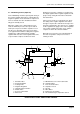
The filtered air then passes from the oil separator
filter by way of the minimum pressure/ non-return
valve (3). Provided the air pressure at this stage is
above 3.5 to 4·0 bar the air passes through the
aftercooler (9) where it is cooled before passing to
the delivery outlet.
If the air pressure in the primary separator vessel
falls below 3.5 to 4·0 bar the minimum pressure
valve will close. The valve also incorporates a non-
return valve which operates to prevent delivery air
passing back into the separator when the
compressor is running off-load.
Oil from the bottom of the separator flows under
pressure to the oil cooler (10) and during normal
running the oil passes through the cooler to
maintain the correct temperature. A thermostatic
bypass valve (14) is installed in the inlet manifold of
the oil cooler.
When the compressor is started, the cold oil in the
system bypasses the cooler and flows through the
oil filter (8) directly to the air-end. As the oil and air
mixture is compressed by the rotors in the air-end,
the temperature of the oil increases.
When the oil has reached its normal operating
temperature the bypass valve closes and the oil is
directed through the oil cooler. The cooled oil then
flows to the oil filter where it is cleaned before
entering the air-end.
The quantity of oil injected into the air-end is
controlled by a restrictor orifice in the air-end
casing. Oil is injected under pressure through the
restrictor orifice into the rotors and a gallery
supplies oil to the air-end bearings.