
User manual


page 45
Cyclon Series User Manual – Operation
4.4 Remote Group Fault Output
4.4.1 Group Fault Relay
The control card is fitted with a group fault relay,
the relay contacts being available for switching
remote facilities. The relay contacts are rated for a
maximum of 250V ac at 5A and are connected to
controller terminal X08, pins 9 and 10.
4.4.2 Group Fault Relay Operation
When power is switched ON, and no alarm or trip
is detected, the group fault relay will energise and
the contacts will close circuit. If an alarm or fault is
detected or a power failure occurs, the relay will
de-energise and the contacts will open circuit. The
relay will energise again when the controller is
reset and no further alarm or trip condition exists.
Controller
X08-9 X08-10
+V~
Fault
0V~
Relay 98475-71
Relay base 98475-72
1 423
57 68
X1/2
X1/1
1
3
6
8
2
4
7
5
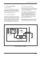
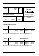
4.4.3 Group Fault Relay - Example
Remote wires (eg from a PLC or building
management system) can be connected directly to
the control card group fault relay contacts available
on pins 9 and 10 of terminal X08.
If the output is used for switching a remote fault
lamp or audible alarm, the group fault relay
contacts will be required to operate in reverse. In
this case an additional relay 98475-71 and base
98475-72 should be fitted, as shown in the
diagram below. This will give a normally open
remote contact which will close when a fault is
detected or power failure occurs.
Note: If the compressor has been out of operation
for a prolonged period it is advisable to carry out
the full commissioning procedure before starting.
GROUP FAULT RELAY – EXAMPLE