
User manual


CompAir BroomWade Limited
page 64
APPENDIX 2
THE PRESSURE SYSTEMS AND
TRANSPORTABLE GAS CONTAINER
REGULATIONS 1989
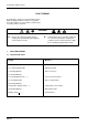
The circuit diagram shown below is provided to
assist a ‘competent person’ in preparing a written
scheme of examination for a system incorporating
the air compressor(s).
Note: The intervals between examination and
calibration of components, eg pressure vessels,
pressure relief valves etc, will be defined by the
‘competent person’ preparing the written scheme.
In defining these periods the ‘competent person’
must take into account the recommendations of
the component part manufacturer, the Health and
Safety Executive (H & SE) and the British
Compressed Air Society (BCAS).
AIR COMPRESSOR CIRCUIT DIAGRAM – ON/OFF CONTROL
8. Separator Filter
9. Pressure Relief Valve
10. Separator Vessel
11. Air-end
12. Drive Motor
13. Intake Pressure Switch
14. Air-end Discharge Temperature Sensor
1. Air Intake Filter
2. Suction Regulator
3. Venting Valve
4. Unloader Solenoid Valve
5. Minimum Pressure/Non-return Valve
6. Pressure Transmitter
7. Aftercooler
M
+-
14
1
13
11 10
9
8
5
7
6
4
3
2
12