United States January 2, 2003 Maintenance & Service Guide Presario 1600 Series Models: 1650 and 1655 | Home Page | Notice | Preface | Product Description | Troubleshooting Illustrated Parts Catalog | Removal & Replacement Procedures | Specifications Pin Assignments | Battery Pack Operations Notice Preface Product Description Troubleshooting Illustrated Parts Catalog Removal & Replacement Procedures Specifications Connector Pin Assignments Battery Pack Operations Welcome to the Maintenance & Service Guid
United States January 2, 2003 Maintenance & Service Guide Presario 1600 Series Models: 1650 and 1655 | Home Page | Notice | Preface | Product Description | Troubleshooting Illustrated Parts Catalog | Removal & Replacement Procedures | Specifications Pin Assignments | Battery Pack Operations Notice The information in this guide is subject to change without notice.
United States January 2, 2003 Maintenance & Service Guide Presario 1600 Series Models: 1650 and 1655 | Home Page | Notice | Preface | Product Description | Troubleshooting Illustrated Parts Catalog | Removal & Replacement Procedures | Specifications Pin Assignments | Battery Pack Operations Preface This Maintenance and Service Guide is a troubleshooting guide that can be used for reference when servicing the Compaq Presario 1600 Series Portable Computers.
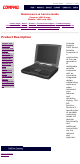
United States January 2, 2003 Maintenance & Service Guide Presario 1600 Series Models: 1650 and 1655 | Home Page | Notice | Preface | Product Description | Troubleshooting Illustrated Parts Catalog | Removal & Replacement Procedures | Specifications Pin Assignments | Battery Pack Operations Product Description Models and Features Controls and Lights Left Side Components Right Side Components Bottom of Unit Rear Connectors Port Replicator Power Management for Windows 98 privacy statement legal notices
United States January 2, 2003 Maintenance & Service Guide Presario 1600 Series Models: 1650 and 1655 | Home Page | Notice | Preface | Product Description | Troubleshooting Illustrated Parts Catalog | Removal & Replacement Procedures | Specifications Pin Assignments | Battery Pack Operations Troubleshooting Preliminary Steps Clearing the Power-On Password Power-On Self Test (POST) Compaq Diagnostics Diagnostic Error Codes Troubleshooting Without Diagnostics Solving Minor Problems Contacting Compaq Support
United States January 2, 2003 Maintenance & Service Guide Presario 1600 Series Models: 1650 and 1655 | Home Page | Notice | Preface | Product Description | Troubleshooting Illustrated Parts Catalog | Removal & Replacement Procedures | Specifications Pin Assignments | Battery Pack Operations Illustrated Parts Catalog System Unit Boards Display Assembly Mass Storage Devices Miscellaneous Cable Kit Cables Miscellaneous Hardware and Plastics Kit Miscellaneous Parts Documentation and Software privacy stateme
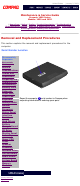
United States January 2, 2003 Maintenance & Service Guide Presario 1600 Series Models: 1650 and 1655 | Home Page | Notice | Preface | Product Description | Troubleshooting Illustrated Parts Catalog | Removal & Replacement Procedures | Specifications Pin Assignments | Battery Pack Operations Removal and Replacement Procedures This section explains the removal and replacement procedures for the computer.
United States January 2, 2003 Maintenance & Service Guide Presario 1600 Series Models: 1650 and 1655 | Home Page | Notice | Preface | Product Description | Troubleshooting Illustrated Parts Catalog | Removal & Replacement Procedures | Specifications Pin Assignments | Battery Pack Operations Specifications This chapter covers the following specifications of Compaq Presario 1600 Series Portable Computers: ● Computer models ● Physical and environmental ● System Interrupts ● System DMA ● System I/O
Maintenance & Service Guide Presario 1600 Series Models: 1650 and 1655 | Home Page | Notice | Preface | Product Description | Troubleshooting Illustrated Parts Catalog | Removal & Replacement Procedures | Specifications Pin Assignments | Battery Pack Operations Connector Pin Assignments This appendix provides connector pin assignment tables for Compaq Presario 1600 Series Portable Computers. For more information on connectors, refer to the section on Rear Connectors.
United States January 2, 2003 Maintenance & Service Guide Presario 1600 Series Models: 1650 and 1655 | Home Page | Notice | Preface | Product Description | Troubleshooting Illustrated Parts Catalog | Removal & Replacement Procedures | Specifications Pin Assignments | Battery Pack Operations Battery Pack Operating Time This appendix covers the following information concerning battery pack operating time: ● ● ● Increase battery pack operating time Conditioning a battery pack Disposal of a used battery pac
United States January 2, 2003 Maintenance & Service Guide Presario 1600 Series Models: 1650 and 1655 | Home Page | Notice | Preface | Product Description | Troubleshooting Illustrated Parts Catalog | Removal & Replacement Procedures | Specifications Pin Assignments | Battery Pack Operations Models and Features Compaq Presario 1600 Series Portable Computer Models Models and Features Controls and Lights Left Side Components Right Side Components Bottom of Unit Rear Connectors Port Replicator Power Manage
United States January 2, 2003 Maintenance & Service Guide Presario 1600 Series Models: 1650 and 1655 | Home Page | Notice | Preface | Product Description | Troubleshooting Illustrated Parts Catalog | Removal & Replacement Procedures | Specifications Pin Assignments | Battery Pack Operations Controls and Lights Models and Features Controls and Lights Left Side Components Right Side Components Bottom of Unit Rear Connectors Port Replicator Power Management for Windows 98 Front of Unit 1. Display 9.
United States January 2, 2003 Maintenance & Service Guide Presario 1600 Series Models: 1650 and 1655 | Home Page | Notice | Preface | Product Description | Troubleshooting Illustrated Parts Catalog | Removal & Replacement Procedures | Specifications Pin Assignments | Battery Pack Operations Left Side Components Models and Features Controls and Lights Left Side Components Right Side Components Bottom of Unit Rear Connectors Port Replicator Power Management for Windows 98 privacy statement legal notices
United States January 2, 2003 Maintenance & Service Guide Presario 1600 Series Models: 1650 and 1655 | Home Page | Notice | Preface | Product Description | Troubleshooting Illustrated Parts Catalog | Removal & Replacement Procedures | Specifications Pin Assignments | Battery Pack Operations Right Side Components Models and Features Controls and Lights Left Side Components Right Side Components Bottom of Unit Rear Connectors Port Replicator Power Management for Windows 98 privacy statement legal notices
United States January 2, 2003 Maintenance & Service Guide Presario 1600 Series Models: 1650 and 1655 | Home Page | Notice | Preface | Product Description | Troubleshooting Illustrated Parts Catalog | Removal & Replacement Procedures | Specifications Pin Assignments | Battery Pack Operations Bottom of Unit Models and Features Controls and Lights Left Side Components Right Side Components Bottom of Unit Rear Connectors Port Replicator Power Management for Windows 98 privacy statement legal notices 1.
United States January 2, 2003 Maintenance & Service Guide Presario 1600 Series Models: 1650 and 1655 | Home Page | Notice | Preface | Product Description | Troubleshooting Illustrated Parts Catalog | Removal & Replacement Procedures | Specifications Pin Assignments | Battery Pack Operations Rear Connectors Models and Features 1.Keyboard/Mouse Port 6. External Monitor Port Controls and Lights 2. Parallel Printer Port 7. USB Left Side Components 3. Port Replicator 8. AC Adapter 4. Fan Exhaust 9.
United States January 2, 2003 Maintenance & Service Guide Presario 1600 Series Models: 1650 and 1655 | Home Page | Notice | Preface | Product Description | Troubleshooting Illustrated Parts Catalog | Removal & Replacement Procedures | Specifications Pin Assignments | Battery Pack Operations Port Replicator Models and Features Controls and Lights Left Side Components Right Side Components Bottom of Unit Rear Connectors Port Replicator Power Management for Windows 98 This section is an overview of the Co
United States January 2, 2003 Maintenance & Service Guide Presario 1600 Series Models: 1650 and 1655 | Home Page | Notice | Preface | Product Description | Troubleshooting Illustrated Parts Catalog | Removal & Replacement Procedures | Specifications Pin Assignments | Battery Pack Operations 80-Pin Port Replicator Connector The 80-pin Compaq Presario 1600 Series Portable Computer Port Replicator connector handles the entire electrical interface between the port Replicator and the computer.
United States January 2, 2003 Maintenance & Service Guide Presario 1600 Series Models: 1650 and 1655 | Home Page | Notice | Preface | Product Description | Troubleshooting Illustrated Parts Catalog | Removal & Replacement Procedures | Specifications Pin Assignments | Battery Pack Operations Port Replicator Rear Connectors This section covers external input/output (I/O) connectors. Refer to Pin Assignments for connector pin assignments. Port Replicator Rear Connectors 1. Keyboard 6. External Monitor 2.
United States January 2, 2003 Maintenance & Service Guide Presario 1600 Series Models: 1650 and 1655 | Home Page | Notice | Preface | Product Description | Troubleshooting Illustrated Parts Catalog | Removal & Replacement Procedures | Specifications Pin Assignments | Battery Pack Operations Power Management for Windows 98 The following power management features are available for conserving AC power and extending battery operating time: Power Management Settings Sleep Hibernation Battery operating time Re
United States January 2, 2003 Maintenance & Service Guide Presario 1600 Series Models: 1650 and 1655 | Home Page | Notice | Preface | Product Description | Troubleshooting Illustrated Parts Catalog | Removal & Replacement Procedures | Specifications Pin Assignments | Battery Pack Operations Removing the Battery Pack Electrostatic Discharge Service Considerations Cables and Connectors Preparing the Computer for Disassembly Battery Pack Palmrest Cover with Touch Pad Keyboard Heatspreader Modem Processor S
United States January 2, 2003 Maintenance & Service Guide Presario 1600 Series Models: 1650 and 1655 | Home Page | Notice | Preface | Product Description | Troubleshooting Illustrated Parts Catalog | Removal & Replacement Procedures | Specifications Pin Assignments | Battery Pack Operations Preliminary Steps Before running POST, complete the following preliminary steps: 1. If a power-on password has been established, type the password and press the Enter key.
United States January 2, 2003 Maintenance & Service Guide Presario 1600 Series Models: 1650 and 1655 | Home Page | Notice | Preface | Product Description | Troubleshooting Illustrated Parts Catalog | Removal & Replacement Procedures | Specifications Pin Assignments | Battery Pack Operations Power-On Self Test (POST) Running POST To run POST, complete the following steps: Turn off the computer, then turn on the computer. If POST does not detect any errors, the computer will not beep.
United States January 2, 2003 Maintenance & Service Guide Presario 1600 Series Models: 1650 and 1655 | Home Page | Notice | Preface | Product Description | Troubleshooting Illustrated Parts Catalog | Removal & Replacement Procedures | Specifications Pin Assignments | Battery Pack Operations Clearing the Power-on Password Clearing the power-on password requires removing all Setup attributes that are programmed in the CMOS. If the password is not known, clear it by performing the following steps: 1.
United States January 2, 2003 Maintenance & Service Guide Presario 1600 Series Models: 1650 and 1655 | Home Page | Notice | Preface | Product Description | Troubleshooting Illustrated Parts Catalog | Removal & Replacement Procedures | Specifications Pin Assignments | Battery Pack Operations Compaq Diagnostics Compaq Diagnostics is installed on the hard drive of the computer. Run the Diagnostics utilities when you want to view or test system information and if you have installed or connected devices.
United States January 2, 2003 Maintenance & Service Guide Presario 1600 Series Models: 1650 and 1655 | Home Page | Notice | Preface | Product Description | Troubleshooting Illustrated Parts Catalog | Removal & Replacement Procedures | Specifications Pin Assignments | Battery Pack Operations Contacting Compaq Support Obtain the following information before contacting Compaq Reseller Support: ● ● ● ● ● ● ● ● ● ● Product name Product serial number Purchase date Conditions under which the problem occurred A
United States January 2, 2003 Maintenance & Service Guide Presario 1600 Series Models: 1650 and 1655 | Home Page | Notice | Preface | Product Description | Troubleshooting Illustrated Parts Catalog | Removal & Replacement Procedures | Specifications Pin Assignments | Battery Pack Operations Diagnostic Error Codes Diagnostic error codes occur if the system recognizes a problem while running the Compaq Diagnostic program. These error codes help identify possibly defective subassemblies.
United States January 2, 2003 Maintenance & Service Guide Presario 1600 Series Models: 1650 and 1655 | Home Page | Notice | Preface | Product Description | Troubleshooting Illustrated Parts Catalog | Removal & Replacement Procedures | Specifications Pin Assignments | Battery Pack Operations Troubleshooting Without Diagnostics This section provides information about how to identify and correct some common hardware, memory, and software problems.
United States January 2, 2003 Maintenance & Service Guide Presario 1600 Series Models: 1650 and 1655 | Home Page | Notice | Preface | Product Description | Troubleshooting Illustrated Parts Catalog | Removal & Replacement Procedures | Specifications Pin Assignments | Battery Pack Operations Solving Minor Problems Some minor problems and possible solutions are outlined in the following tables. If the problem appears related to a software application, check the documentation provided with the software.
United States January 2, 2003 Maintenance & Service Guide Presario 1600 Series Models: 1650 and 1655 | Home Page | Notice | Preface | Product Description | Troubleshooting Illustrated Parts Catalog | Removal & Replacement Procedures | Specifications Pin Assignments | Battery Pack Operations Solving PC Card Problems Some common causes and solutions for PC Card problems are listed in the following table.
United States January 2, 2003 Maintenance & Service Guide Presario 1600 Series Models: 1650 and 1655 | Home Page | Notice | Preface | Product Description | Troubleshooting Illustrated Parts Catalog | Removal & Replacement Procedures | Specifications Pin Assignments | Battery Pack Operations System Unit System Unit Description Boards Display Assembly Mass Storage Devices 1. Status Panel Spare Part Number 293737001 2. Palmrest Cover 332226001 3.
United States January 2, 2003 Maintenance & Service Guide Presario 1600 Series Models: 1650 and 1655 | Home Page | Notice | Preface | Product Description | Troubleshooting Illustrated Parts Catalog | Removal & Replacement Procedures | Specifications Pin Assignments | Battery Pack Operations Boards System Unit Description Spare Part Number 1.Heatspreader 331164001 2.Processor Pentium II/233 Processor Pentium II/266 347556001 3. Audio Board 331010001 4.
United States January 2, 2003 Maintenance & Service Guide Presario 1600 Series Models: 1650 and 1655 | Home Page | Notice | Preface | Product Description | Troubleshooting Illustrated Parts Catalog | Removal & Replacement Procedures | Specifications Pin Assignments | Battery Pack Operations System Unit Boards Display Assembly Mass Storage Devices Miscellaneous Cable Kit Description Spare Part Number Display Assembly w/Cable, 12.
United States January 2, 2003 Maintenance & Service Guide Presario 1600 Series Models: 1650 and 1655 | Home Page | Notice | Preface | Product Description | Troubleshooting Illustrated Parts Catalog | Removal & Replacement Procedures | Specifications Pin Assignments | Battery Pack Operations Mass Storage Devices System Unit Description Boards Display Assembly Spare Part Number 1. Diskette Drive w/Cable, 1.44 MB, 3.5 inch 331165001 2. Hard Drive w/Mounting Bracket, 5.
United States January 2, 2003 Maintenance & Service Guide Presario 1600 Series Models: 1650 and 1655 | Home Page | Notice | Preface | Product Description | Troubleshooting Illustrated Parts Catalog | Removal & Replacement Procedures | Specifications Pin Assignments | Battery Pack Operations Miscellaneous Cables Kit System Unit Boards Display Assembly Mass Storage Devices Miscellaneous Cables Kit Spare Part Number: 332234-001 Description Quantity Miscellaneous Cable Kit 1a.
United States January 2, 2003 Maintenance & Service Guide Presario 1600 Series Models: 1650 and 1655 | Home Page | Notice | Preface | Product Description | Troubleshooting Illustrated Parts Catalog | Removal & Replacement Procedures | Specifications Pin Assignments | Battery Pack Operations System Unit Boards Display Assembly Power Cords Description Spare Part Number Power Cord Mass Storage Devices United States/ French Canada International 293831-001 293831-002 Miscellaneous Cable Kit Cables Mis
United States January 2, 2003 Maintenance & Service Guide Presario 1600 Series Models: 1650 and 1655 | Home Page | Notice | Preface | Product Description | Troubleshooting Illustrated Parts Catalog | Removal & Replacement Procedures | Specifications Pin Assignments | Battery Pack Operations Miscellaneous Hardware and Plastics Kit System Unit Boards Display Assembly Mass Storage Devices Miscellaneous Hardware and Plastics Kit Spare Part Number: 293761-001 Description Quantity 1.
United States January 2, 2003 Maintenance & Service Guide Presario 1600 Series Models: 1650 and 1655 | Home Page | Notice | Preface | Product Description | Troubleshooting Illustrated Parts Catalog | Removal & Replacement Procedures | Specifications Pin Assignments | Battery Pack Operations Miscellaneous Parts System Unit Boards Display Assembly Mass Storage Devices Miscellaneous Cable Kit Cables Miscellaneous Hardware and Plastics Kit Miscellaneous Parts Documentation and Software privacy statement leg
United States January 2, 2003 Maintenance & Service Guide Presario 1600 Series Models: 1650 and 1655 | Home Page | Notice | Preface | Product Description | Troubleshooting Illustrated Parts Catalog | Removal & Replacement Procedures | Specifications Pin Assignments | Battery Pack Operations Documentation and Software System Unit Description Boards Quick Restore CD Spare Part Number Display Assembly Not Available Mass Storage Devices Not Available Miscellaneous Cable Kit Cables Miscellaneous Hard
United States January 2, 2003 Maintenance & Service Guide Presario 1600 Series Models: 1650 and 1655 | Home Page | Notice | Preface | Product Description | Troubleshooting Illustrated Parts Catalog | Removal & Replacement Procedures | Specifications Pin Assignments | Battery Pack Operations Electrostatic Discharge A sudden discharge of static electricity from a finger or other conductor can destroy static-sensitive devices or microcircuitry. Often the spark is neither felt nor heard, but damage occurs.
United States January 2, 2003 Maintenance & Service Guide Presario 1600 Series Models: 1650 and 1655 | Home Page | Notice | Preface | Product Description | Troubleshooting Illustrated Parts Catalog | Removal & Replacement Procedures | Specifications Pin Assignments | Battery Pack Operations Service Considerations Listed below are some of the considerations that you should keep in mind during the disassembly and assembly of the computer.
United States January 2, 2003 Maintenance & Service Guide Presario 1600 Series Models: 1650 and 1655 | Home Page | Notice | Preface | Product Description | Troubleshooting Illustrated Parts Catalog | Removal & Replacement Procedures | Specifications Pin Assignments | Battery Pack Operations Cables and Connectors Most cables used throughout the unit are ribbon cables. Cables must be handled with extreme care to avoid damage.
United States January 2, 2003 Maintenance & Service Guide Presario 1600 Series Models: 1650 and 1655 | Home Page | Notice | Preface | Product Description | Troubleshooting Illustrated Parts Catalog | Removal & Replacement Procedures | Specifications Pin Assignments | Battery Pack Operations ZIF Connectors The computer uses a zero insertion force (ZIF) connector for the keyboard cable to the system board.
United States January 2, 2003 Maintenance & Service Guide Presario 1600 Series Models: 1650 and 1655 | Home Page | Notice | Preface | Product Description | Troubleshooting Illustrated Parts Catalog | Removal & Replacement Procedures | Specifications Pin Assignments | Battery Pack Operations The ribbon cable position for the 5.0-GB or 4.0-GB hard drive. Back to Cables and Connectors.
United States January 2, 2003 Maintenance & Service Guide Presario 1600 Series Models: 1650 and 1655 | Home Page | Notice | Preface | Product Description | Troubleshooting Illustrated Parts Catalog | Removal & Replacement Procedures | Specifications Pin Assignments | Battery Pack Operations The ribbon cable position for the CD drive. Back to Cables and Connectors.
United States January 2, 2003 Maintenance & Service Guide Presario 1600 Series Models: 1650 and 1655 | Home Page | Notice | Preface | Product Description | Troubleshooting Illustrated Parts Catalog | Removal & Replacement Procedures | Specifications Pin Assignments | Battery Pack Operations The ribbon cable position for the diskette drive. Back to Cables and Connectors.
United States January 2, 2003 Maintenance & Service Guide Presario 1600 Series Models: 1650 and 1655 | Home Page | Notice | Preface | Product Description | Troubleshooting Illustrated Parts Catalog | Removal & Replacement Procedures | Specifications Pin Assignments | Battery Pack Operations The cable position for the speaker assembly. Back to Cables and Connectors.
United States January 2, 2003 Maintenance & Service Guide Presario 1600 Series Models: 1650 and 1655 | Home Page | Notice | Preface | Product Description | Troubleshooting Illustrated Parts Catalog | Removal & Replacement Procedures | Specifications Pin Assignments | Battery Pack Operations Preparing the Computer for Disassembly Electrostatic Discharge Before beginning removal and replacement procedures, complete the following procedures: Service 1. Disconnect AC power and any external devices.
United States January 2, 2003 Maintenance & Service Guide Presario 1600 Series Models: 1650 and 1655 | Home Page | Notice | Preface | Product Description | Troubleshooting Illustrated Parts Catalog | Removal & Replacement Procedures | Specifications Pin Assignments | Battery Pack Operations Removing the Palmrest Cover with Touch Pad Electrostatic Discharge Service Considerations Cables and Connectors Preparing the Computer for Disassembly Battery Pack Palmrest Cover with Touch Pad Keyboard Heatspreader
United States January 2, 2003 Maintenance & Service Guide Presario 1600 Series Models: 1650 and 1655 | Home Page | Notice | Preface | Product Description | Troubleshooting Illustrated Parts Catalog | Removal & Replacement Procedures | Specifications Pin Assignments | Battery Pack Operations 4. Turn the computer over (right side up), pull forward on the display latches to release and open the display assembly. 5.
United States January 2, 2003 Maintenance & Service Guide Presario 1600 Series Models: 1650 and 1655 | Home Page | Notice | Preface | Product Description | Troubleshooting Illustrated Parts Catalog | Removal & Replacement Procedures | Specifications Pin Assignments | Battery Pack Operations Removing the Keyboard Electrostatic Discharge Service Considerations Cables and Connectors Preparing the Computer for Disassembly Battery Pack Palmrest Cover with Touch Pad Keyboard Heatspreader Modem To remove the
United States January 2, 2003 Maintenance & Service Guide Presario 1600 Series Models: 1650 and 1655 | Home Page | Notice | Preface | Product Description | Troubleshooting Illustrated Parts Catalog | Removal & Replacement Procedures | Specifications Pin Assignments | Battery Pack Operations 4. Lift the keyboard out of the chassis. To replace the keyboard, reverse the previous procedures.
United States January 2, 2003 Maintenance & Service Guide Presario 1600 Series Models: 1650 and 1655 | Home Page | Notice | Preface | Product Description | Troubleshooting Illustrated Parts Catalog | Removal & Replacement Procedures | Specifications Pin Assignments | Battery Pack Operations Removing the Heatspreader Electrostatic Discharge Service Considerations Cables and Connectors Preparing the Computer for Disassembly Battery Pack Palmrest Cover with Touch Pad Keyboard Heatspreader Modem Processor S
United States January 2, 2003 Maintenance & Service Guide Presario 1600 Series Models: 1650 and 1655 | Home Page | Notice | Preface | Product Description | Troubleshooting Illustrated Parts Catalog | Removal & Replacement Procedures | Specifications Pin Assignments | Battery Pack Operations Removing the Modem Electrostatic Discharge Service Considerations Cables and Connectors Preparing the Computer for Disassembly Battery Pack Palmrest Cover with Touch Pad Keyboard Heatspreader Modem Processor Status P
United States January 2, 2003 Maintenance & Service Guide Presario 1600 Series Models: 1650 and 1655 | Home Page | Notice | Preface | Product Description | Troubleshooting Illustrated Parts Catalog | Removal & Replacement Procedures | Specifications Pin Assignments | Battery Pack Operations 6. Disconnect the modem cable from the modem. To replace the modem, reverse the previous procedures.
United States January 2, 2003 Maintenance & Service Guide Presario 1600 Series Models: 1650 and 1655 | Home Page | Notice | Preface | Product Description | Troubleshooting Illustrated Parts Catalog | Removal & Replacement Procedures | Specifications Pin Assignments | Battery Pack Operations Removing the Processor Electrostatic Discharge Service Considerations Cables and Connectors Preparing the Computer for Disassembly Battery Pack Palmrest Cover with Touch Pad Keyboard Heatspreader Modem Processor Stat
United States January 2, 2003 Maintenance & Service Guide Presario 1600 Series Models: 1650 and 1655 | Home Page | Notice | Preface | Product Description | Troubleshooting Illustrated Parts Catalog | Removal & Replacement Procedures | Specifications Pin Assignments | Battery Pack Operations 7. Insert a small blade screw driver under the right side on the processor and lift the processor from the chassis slot. 8. Lift the processor out of the processor chassis slot.
United States January 2, 2003 Maintenance & Service Guide Presario 1600 Series Models: 1650 and 1655 | Home Page | Notice | Preface | Product Description | Troubleshooting Illustrated Parts Catalog | Removal & Replacement Procedures | Specifications Pin Assignments | Battery Pack Operations Removing the Status Panel Electrostatic Discharge Service Considerations Cables and Connectors Preparing the Computer for Disassembly Battery Pack Palmrest Cover with Touch Pad Keyboard Heatspreader Modem Processor S
United States January 2, 2003 Maintenance & Service Guide Presario 1600 Series Models: 1650 and 1655 | Home Page | Notice | Preface | Product Description | Troubleshooting Illustrated Parts Catalog | Removal & Replacement Procedures | Specifications Pin Assignments | Battery Pack Operations 6. Disconnect the flex cable from the connector on the status panel header.
United States January 2, 2003 Maintenance & Service Guide Presario 1600 Series Models: 1650 and 1655 | Home Page | Notice | Preface | Product Description | Troubleshooting Illustrated Parts Catalog | Removal & Replacement Procedures | Specifications Pin Assignments | Battery Pack Operations Removing the Interface Board with Header Electrostatic Discharge Service Considerations Cables and Connectors Preparing the Computer for Disassembly Battery Pack Palmrest Cover with Touch Pad Keyboard Heatspreader Mo
United States January 2, 2003 Maintenance & Service Guide Presario 1600 Series Models: 1650 and 1655 | Home Page | Notice | Preface | Product Description | Troubleshooting Illustrated Parts Catalog | Removal & Replacement Procedures | Specifications Pin Assignments | Battery Pack Operations 6. Slightly lift the interface board, disconnect the ZIF connector, and backlight power cable from the interface board.
United States January 2, 2003 Maintenance & Service Guide Presario 1600 Series Models: 1650 and 1655 | Home Page | Notice | Preface | Product Description | Troubleshooting Illustrated Parts Catalog | Removal & Replacement Procedures | Specifications Pin Assignments | Battery Pack Operations 7. Lift the interface board up with the header attached from the system board. .
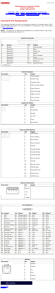
United States January 2, 2003 The following illustration and table indicates the locations of the connectors on the interface board. Interface Board Components Designator Connector 1. JP1 Backlight Switch 2. JP3 Display Interface ZIF 3. JP4 Inverter/Backlight LIF Connector 4.
United States January 2, 2003 Maintenance & Service Guide Presario 1600 Series Models: 1650 and 1655 | Home Page | Notice | Preface | Product Description | Troubleshooting Illustrated Parts Catalog | Removal & Replacement Procedures | Specifications Pin Assignments | Battery Pack Operations Removing the 5.0-GB or 4.
United States January 2, 2003 Maintenance & Service Guide Presario 1600 Series Models: 1650 and 1655 | Home Page | Notice | Preface | Product Description | Troubleshooting Illustrated Parts Catalog | Removal & Replacement Procedures | Specifications Pin Assignments | Battery Pack Operations 5. Disconnect the hard drive data cable from the hard drive and remove from the chassis.
United States January 2, 2003 Maintenance & Service Guide Presario 1600 Series Models: 1650 and 1655 | Home Page | Notice | Preface | Product Description | Troubleshooting Illustrated Parts Catalog | Removal & Replacement Procedures | Specifications Pin Assignments | Battery Pack Operations To remove the hard drive mounting bracket, complete the following step: Remove four screws from the hard drive mounting bracket.
United States January 2, 2003 Maintenance & Service Guide Presario 1600 Series Models: 1650 and 1655 | Home Page | Notice | Preface | Product Description | Troubleshooting Illustrated Parts Catalog | Removal & Replacement Procedures | Specifications Pin Assignments | Battery Pack Operations Removing the Battery Charger Board To remove the battery charger board, complete the following steps: Electrostatic Discharge Service Considerations 1. Prepare the computer for disassembly.
United States January 2, 2003 Maintenance & Service Guide Presario 1600 Series Models: 1650 and 1655 | Home Page | Notice | Preface | Product Description | Troubleshooting Illustrated Parts Catalog | Removal & Replacement Procedures | Specifications Pin Assignments | Battery Pack Operations Removing the CD Drive Electrostatic Discharge Service Considerations Cables and Connectors Preparing the Computer for Disassembly Battery Pack Palmrest Cover with Touch Pad Keyboard Heatspreader Modem Processor Statu
United States January 2, 2003 Maintenance & Service Guide Presario 1600 Series Models: 1650 and 1655 | Home Page | Notice | Preface | Product Description | Troubleshooting Illustrated Parts Catalog | Removal & Replacement Procedures | Specifications Pin Assignments | Battery Pack Operations 8. Disconnect the CD drive cable from the system board. To replace the CD drive, reverse the previous procedures.
United States January 2, 2003 Maintenance & Service Guide Presario 1600 Series Models: 1650 and 1655 | Home Page | Notice | Preface | Product Description | Troubleshooting Illustrated Parts Catalog | Removal & Replacement Procedures | Specifications Pin Assignments | Battery Pack Operations Removing the Display Panel Assembly Electrostatic Discharge Service Considerations Cables and Connectors Preparing the Computer for Disassembly Battery Pack Palmrest Cover with Touch Pad To remove the display panel
United States January 2, 2003 Maintenance & Service Guide Presario 1600 Series Models: 1650 and 1655 | Home Page | Notice | Preface | Product Description | Troubleshooting Illustrated Parts Catalog | Removal & Replacement Procedures | Specifications Pin Assignments | Battery Pack Operations 8. Support the back of the display panel assembly and remove two screws from each of the display panel hinges.
United States January 2, 2003 Maintenance & Service Guide Presario 1600 Series Models: 1650 and 1655 | Home Page | Notice | Preface | Product Description | Troubleshooting Illustrated Parts Catalog | Removal & Replacement Procedures | Specifications Pin Assignments | Battery Pack Operations 9. Disconnect the backlight cable attached to the display panel assembly from the connector on the system board.
United States January 2, 2003 Maintenance & Service Guide Presario 1600 Series Models: 1650 and 1655 | Home Page | Notice | Preface | Product Description | Troubleshooting Illustrated Parts Catalog | Removal & Replacement Procedures | Specifications Pin Assignments | Battery Pack Operations Removing the Upper CPU Cover To remove the Upper CPU cover complete the following steps: Electrostatic Discharge Service Considerations Cables and Connectors Preparing the Computer for Disassembly Battery Pack Palmre
United States January 2, 2003 Maintenance & Service Guide Presario 1600 Series Models: 1650 and 1655 | Home Page | Notice | Preface | Product Description | Troubleshooting Illustrated Parts Catalog | Removal & Replacement Procedures | Specifications Pin Assignments | Battery Pack Operations Removing the Speaker Assembly To remove the speaker assembly, complete the following steps: 1. Prepare the computer for disassembly. 2. Remove the palmrest cover with touch pad.
United States January 2, 2003 Maintenance & Service Guide Presario 1600 Series Models: 1650 and 1655 | Home Page | Notice | Preface | Product Description | Troubleshooting Illustrated Parts Catalog | Removal & Replacement Procedures | Specifications Pin Assignments | Battery Pack Operations Removing the Diskette Drive Electrostatic Discharge Service Considerations Cables and Connectors Preparing the Computer for Disassembly Battery Pack Palmrest Cover with Touch Pad Keyboard To remove the diskette driv
United States January 2, 2003 Maintenance & Service Guide Presario 1600 Series Models: 1650 and 1655 | Home Page | Notice | Preface | Product Description | Troubleshooting Illustrated Parts Catalog | Removal & Replacement Procedures | Specifications Pin Assignments | Battery Pack Operations 7. Disconnect the diskette drive data cable from the system board.
United States January 2, 2003 Maintenance & Service Guide Presario 1600 Series Models: 1650 and 1655 | Home Page | Notice | Preface | Product Description | Troubleshooting Illustrated Parts Catalog | Removal & Replacement Procedures | Specifications Pin Assignments | Battery Pack Operations 8. Unscrew the diskette drive standoff and screw (left corner) from the system board. Lift the diskette drive off the alignment pegs and remove from the chassis.
United States January 2, 2003 Maintenance & Service Guide Presario 1600 Series Models: 1650 and 1655 | Home Page | Notice | Preface | Product Description | Troubleshooting Illustrated Parts Catalog | Removal & Replacement Procedures | Specifications Pin Assignments | Battery Pack Operations Removing the Fan Assembly To remove the fan assembly, complete the following steps: 1. Prepare the computer for disassembly. Electrostatic Discharge Service Considerations 2.
United States January 2, 2003 Maintenance & Service Guide Presario 1600 Series Models: 1650 and 1655 | Home Page | Notice | Preface | Product Description | Troubleshooting Illustrated Parts Catalog | Removal & Replacement Procedures | Specifications Pin Assignments | Battery Pack Operations Removing the Audio Board Electrostatic Discharge Service Considerations Cables and Connectors Preparing the Computer for Disassembly Battery Pack Palmrest Cover with Touch Pad Keyboard Heatspreader Modem To remove t
United States January 2, 2003 Maintenance & Service Guide Presario 1600 Series Models: 1650 and 1655 | Home Page | Notice | Preface | Product Description | Troubleshooting Illustrated Parts Catalog | Removal & Replacement Procedures | Specifications Pin Assignments | Battery Pack Operations 9. Push to the right on the latch to separate the audio board from the base pan while disconnecting the audio board from the connector on the system board. To replace the audio board, reverse the previous procedures.
United States January 2, 2003 Maintenance & Service Guide Presario 1600 Series Models: 1650 and 1655 | Home Page | Notice | Preface | Product Description | Troubleshooting Illustrated Parts Catalog | Removal & Replacement Procedures | Specifications Pin Assignments | Battery Pack Operations Removing the System Board Electrostatic Discharge To remove the system board, complete the following steps: 1. Service Considerations 2. Cables and Connectors 3. Preparing the Computer for 4.
United States January 2, 2003 Maintenance & Service Guide Presario 1600 Series Models: 1650 and 1655 | Home Page | Notice | Preface | Product Description | Troubleshooting Illustrated Parts Catalog | Removal & Replacement Procedures | Specifications Pin Assignments | Battery Pack Operations 19. Remove five standoffs from the system board.
United States January 2, 2003 Maintenance & Service Guide Presario 1600 Series Models: 1650 and 1655 | Home Page | Notice | Preface | Product Description | Troubleshooting Illustrated Parts Catalog | Removal & Replacement Procedures | Specifications Pin Assignments | Battery Pack Operations 20. Remove three screws from the system board.
United States January 2, 2003 Maintenance & Service Guide Presario 1600 Series Models: 1650 and 1655 | Home Page | Notice | Preface | Product Description | Troubleshooting Illustrated Parts Catalog | Removal & Replacement Procedures | Specifications Pin Assignments | Battery Pack Operations 21. Push in the PCMCIA eject levers, lift up the front end of the system board, pull forward, and remove the system board from the chassis. To replace the system board, reverse the previous procedures.
United States January 2, 2003 Maintenance & Service Guide Presario 1600 Series Models: 1650 and 1655 | Home Page | Notice | Preface | Product Description | Troubleshooting Illustrated Parts Catalog | Removal & Replacement Procedures | Specifications Pin Assignments | Battery Pack Operations Removing the Memory Module Electrostatic Discharge Service Considerations Cables and Connectors Preparing the Computer for Disassembly Battery Pack Palmrest Cover with Touch Pad Keyboard Heatspreader Modem Processor
United States January 2, 2003 Maintenance & Service Guide Presario 1600 Series Models: 1650 and 1655 | Home Page | Notice | Preface | Product Description | Troubleshooting Illustrated Parts Catalog | Removal & Replacement Procedures | Specifications Pin Assignments | Battery Pack Operations 4. Pull side levers to release the memory unplug module and the memory module from the system board. To replace the memory module, reverse the previous procedures.