ProLiant ML370 Maintenance and Service Guide Fourth Edition (June 2000) Part Number 143091-004 Spare Part Number 158549-001 Compaq Computer Corporation
Notice The information in this publication is subject to change without notice. COMPAQ COMPUTER CORPORATION SHALL NOT BE LIABLE FOR TECHNICAL OR EDITORIAL ERRORS OR OMISSIONS CONTAINED HEREIN, NOR FOR INCIDENTAL OR CONSEQUENTIAL DAMAGES RESULTING FROM THE FURNISHING, PERFORMANCE, OR USE OF THIS MATERIAL.
Contents About This Guide Symbols in Text.........................................................................................................vii Compaq Technician Notes .......................................................................................viii Where to Go for Additional Help .............................................................................viii Integrated Management Display.......................................................................... ix Telephone Numbers ......
iv Compaq ProLiant ML370 Maintenance and Service Guide Removal and Replacement Procedures continued I/O Fan....................................................................................................................2-22 Power Switch with Cable and LED Indicators .......................................................2-23 Riser Board Expansion Slots ..................................................................................2-25 I/O Expansion Slot Cover.......................................
Contents v Diagnostics and Troubleshooting continued Remote Service Features ........................................................................................3-64 ROMPaq Error Recovery Options..........................................................................3-64 ROMPaq Disaster Recovery ...........................................................................3-65 Compaq Insight Manager .......................................................................................
About This Guide This maintenance and service guide is a troubleshooting guide that can be used for reference when servicing Compaq ProLiant ML370 Servers. WARNING: To reduce the risk of personal injury from electric shock and hazardous energy levels, only authorized service technicians should attempt to repair this equipment. Improper repairs could create conditions that are hazardous.
viii Compaq ProLiant ML370 Maintenance and Service Guide Compaq Technician Notes WARNING: Only authorized technicians trained by Compaq should attempt to repair this equipment. All troubleshooting and repair procedures are detailed to allow only subassembly/module-level repair. Because of the complexity of the individual boards and subassemblies, no one should attempt to make repairs at the component level or to make modifications to any printed wiring board. Improper repairs can create a safety hazard.
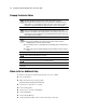
About This Guide Integrated Management Display Some Compaq server models include a Compaq Integrated Management Display (IMD), an integrated, 16 × 4 character display mounted on the front of the server. This display provides easy-to-use menu-driven access to server information, including model number, LCD firmware revision, and POST operations. Telephone Numbers For the name of your nearest Compaq authorized reseller: ■ In the United States, call 1-800-345-1518. ■ In Canada, call 1-800-263-5868.
Chapter 1 Illustrated Parts Catalog This chapter provides the illustrated parts breakdown and a spare parts list for Compaq ProLiant™ ML370 Servers. See Table 1-1 and Table 1-2 for the names of referenced spare parts.
1-2 Compaq ProLiant ML370 Maintenance and Service Guide Mechanical Parts Exploded View 2 4 3 1 6 5 7 8 Figure 1-1.
Illustrated Parts Catalog 1-3 Mechanical Spare Parts List Table 1-1 Mechanical Spare Parts List Item Description Spare Part Number Chassis 1 Chassis 157986-001 2 Small access panel Part of kit 387762-001 3 Large access panel Part of kit 387762-001 4 Right side panel (tower model only) Part of kit 387762-001 5 Front bezel (tower model only) 217492-001 6 Rack front plate (rack-mountable model only) 163489-001 7 Feet (tower model only) 333575-001 8 Hot-plug drive cage, 6 x 1-inch 387
1-4 Compaq ProLiant ML370 Maintenance and Service Guide System Components Exploded View 12 15 17 13 19 14a 1 16 10 20 21a 11 22 9 18 8 26 27a Figure 1-2.
Illustrated Parts Catalog 1-5 System Components Spare Parts Table 1-2 System Components Spare Parts List Item Description Spare Part Number System Components 9 Power supply, 325 W 402151-001 10 I/O fan, 92 mm 173907-001 11 CPU fan, 120 mm 326873-001 12 3V lithium battery 179322-001 13 Power switch with LED indicators and cable 157928-001 Boards 14 Processors a) 6/600-MHz, with heat sink (heat sink may vary) 166146-001 b) 6/667-MHz, with heat sink (heat sink may vary)* 166109-001 c) 6
1-6 Compaq ProLiant ML370 Maintenance and Service Guide Table 1-2 System Components Spare Parts List continued Item Description Spare Part Number Cables continued 24 Miscellaneous signal cable kit * 158530-001 a) Hard drive/CD-ROM drive data cable b) Diskette drive cable assembly c) 1-device SCSI cable assembly d) 3-device SCSI cable assembly 25 Miscellaneous power cable kit * 158529-001 a) Diskette and CD-ROM drive power cable assembly b) Power supply power cable assembly c) Removable media bay p
Illustrated Parts Catalog 1-7 Table 1-2 System Components Spare Parts List continued Item Description Spare Part Number Options continued 42 9.
Chapter 2 Removal and Replacement Procedures This chapter provides subassembly/module-level removal and replacement procedures for Compaq ProLiant ML370 Servers. The ProLiant ML370 Server is available in tower and rack models. The Compaq ProLiant ML370 Maintenance and Service Guide shows the tower model. In most cases, the rack model removal and replacement procedures are slightly different from the tower model procedures.
2-2 Compaq ProLiant ML370 Maintenance and Service Guide Electrostatic Discharge Information A discharge of static electricity can damage static-sensitive devices or microcircuitry. Proper packaging and grounding techniques are necessary precautions to prevent damage. To prevent electrostatic damage, observe the following precautions: ■ Transport products in static-safe containers such as conductive tubes, bags, or boxes.
Removal and Replacement Procedures Any product or assembly marked with these symbols indicates that the component exceeds the recommended weight for one individual to handle safely. Weight in kg Weight in lb Preparation Procedures Before beginning to remove any serviceable parts, determine whether the part is hot-pluggable or non-hot-pluggable. Hot-Pluggable Devices Hot-pluggable devices in the ProLiant ML370 Servers include SCSI hard drives and power supplies (with redundant power supply option kit).
2-4 Compaq ProLiant ML370 Maintenance and Service Guide WARNING: To reduce the risk of personal injury or damage to the equipment: If the server is mounted in a rack, internal devices may not be accessible for removal and replacement. If the server must be removed from the rack for device accessibility, remove the server from the rack and place it on a sturdy table or workbench. Refer to the ProLiant ML370 Servers Setup and Installation Guide for further information on working with racks.
Removal and Replacement Procedures Server Warnings and Precautions WARNING: To reduce the risk of personal injury from hot surfaces, allow the internal system components to cool before touching. WARNING: To reduce the risk of electric shock or damage to the equipment: ■ Do not disable the power cord grounding plug. The grounding plug is an important safety feature. ■ Plug the power cord into a grounded (earthed) electrical outlet that is easily accessible at all times.
2-6 Compaq ProLiant ML370 Maintenance and Service Guide Front Bezel NOTE: This procedure applies to the ProLiant ML370 tower model only. To open the front bezel: 1. Unlock the front bezel keylock. 2. Swing the front bezel out away from the server. To remove the front bezel, continue with the following step. 3. Lift up the front bezel, then pull it away from the chassis. Figure 2-1. Removing the front bezel Reverse steps 1 through 3 to replace the front bezel.
Removal and Replacement Procedures Rack Front Plate NOTE: This procedure applies to the ProLiant ML370 rack-mountable model only. To remove the rack front plate: 1. Remove the ten T-15 screws from the rack front plate 2. Pull the rack front plate away from the server . . 2 1 Figure 2-2. Removing the rack front plate Reverse steps 1 and 2 to replace the rack front plate.
2-8 Compaq ProLiant ML370 Maintenance and Service Guide Feet NOTE: This procedure applies to the ProLiant ML370 tower model only. To remove the feet from the chassis, one at a time: 1. Perform the preparation procedures. See “Powering Down the Server” earlier in this chapter. 2. Place the server on its right side (opposite from the large access panel). 3. Remove the T-15 screw from each foot ➊. 4. Pivot each foot down ➋; then pull it off the base of the chassis ➌. 3 2 1 Figure 2-3.
Removal and Replacement Procedures Large Access Panel WARNING: To reduce the risk of personal injury from hot surfaces, allow internal system components to cool before touching them. To remove the large access panel: 1. Perform the preparation procedures. See “Powering Down the Server” earlier in this chapter. 2. Open the front bezel (tower model only). See “Front Bezel” earlier in this chapter. 3. Loosen the two thumbscrews securing the large access panel to the front of the chassis 4.
2-10 Compaq ProLiant ML370 Maintenance and Service Guide Small Access Panel WARNING: To reduce the risk of personal injury from hot surfaces, allow internal system components to cool before touching them. To remove the small access panel: 1. Perform the preparation procedures. See “Powering Down the Server” earlier in this chapter. 2. Open the front bezel (tower model only). See “Front Bezel” earlier in this chapter. 3. Loosen the thumbscrew securing the small access panel to the chassis ➊. 4.
Removal and Replacement Procedures Right Side Panel NOTE: This panel does not exist on the rack-mountable model. This procedure applies to the tower model only. To remove the right side panel from the chassis: 1. Perform the preparation procedures. See “Powering Down the Server” earlier in this chapter. 2. Remove the front bezel (tower model only). See “Front Bezel” earlier in this chapter. 3. Remove the feet on the base of the right side panel. See “Feet” earlier in this chapter. 4.
2-12 Compaq ProLiant ML370 Maintenance and Service Guide Drives and Related Components Compaq ProLiant ML370 Servers ship standard with a hot-plug drive cage containing six 1.0-inch hot-plug drive bays. Four removable media bays contain one third-height diskette drive and one half-height IDE CD-ROM drive. Two bays can contain a second CD-ROM drive, tape drives, hard drives, or any SCSI device.
Removal and Replacement Procedures Cable Routing Diagrams CAUTION: When routing cables, always ensure that the cables are not in a position where they will be pinched or crimped. IDE CD-ROM Drive Cable Diagram 1 1 Figure 2-8. IDE CD-ROM drive cable Diskette Drive Cable Diagram 1 1 Figure 2-9.
2-14 Compaq ProLiant ML370 Maintenance and Service Guide SCSI Cable Diagram 1 2 1 2 Figure 2-10.
Removal and Replacement Procedures Hot-Plug Drive Cage To remove the hot-plug drive cage: 1. Perform the preparation procedures. See “Powering Down the Server” earlier in this chapter. 2. Remove the front bezel (tower model only). See “Front Bezel” earlier in this chapter. 3. Remove the large access panel. See “Large Access Panel” earlier in this chapter. 4. Disconnect all cables from the hot-plug drive cage: one SCSI cable and two power connectors. 5.
2-16 Compaq ProLiant ML370 Maintenance and Service Guide IDE CD-ROM Drive To remove the CD-ROM drive: 1. Perform the preparation procedures. See “Powering Down the Server” earlier in this chapter. 2. Open the front bezel (tower model only). See “Front Bezel” earlier in this chapter. 3. Remove the large access panel. See “Large Access Panel” earlier in this chapter. 4. Disconnect all cables from the CD-ROM drive. 5. Remove the two T-15 screws and washers securing the CD-ROM drive to the chassis 6.
Removal and Replacement Procedures Diskette Drive To remove the diskette drive: 1. Perform the preparation procedures. See “Powering Down the Server” earlier in this chapter. 2. Open the front bezel (tower model only). See “Front Bezel” earlier in this chapter. 3. Remove the large access panel. See “Large Access Panel” earlier in this chapter. 4. Disconnect all cables from the diskette drive. 5. Remove the two T-15 screws and washers securing the diskette drive to the chassis 6.
2-18 Compaq ProLiant ML370 Maintenance and Service Guide Hard Drive Blank IMPORTANT: A hard drive blank must be installed in an unused hard drive slot. Failure to install a hard drive blank could result in system errors. To remove a hard drive blank: 1. Open the front bezel (tower model only). See “Front Bezel” earlier in this chapter. 2. Squeeze the top and bottom tabs of the blank 3. Pull the blank out of the hard drive cage . . 1 2 1 Figure 2-14.
Removal and Replacement Procedures Hot-Plug SCSI Hard Drive To remove a hot-plug SCSI hard drive: 1. Open the front bezel (tower model only). See “Front Bezel” earlier in this chapter. and swing the lever outward from the bottom. 3. Pull the hot-plug SCSI hard drive out of the bay . 2. Press the release button 2 1 3 Figure 2-15. Removing a hot-plug SCSI hard drive Reverse steps 1 through 3 to replace the hot-plug SCSI hard drive.
2-20 Compaq ProLiant ML370 Maintenance and Service Guide Removable Media Drive Bay Blank To remove a removable media drive bay blank: 1. Open the front bezel (tower model only). See “Front Bezel” earlier in this chapter. 2. Remove the four Torx T-15 screws securing the removable media drive bay blank to the chassis . 3. Remove the removable media drive bay blank . 2 1 1 Figure 2-16. Removing a removable media drive bay blank Reverse steps 1 through 3 to replace a removable media drive bay blank.
Removal and Replacement Procedures CPU Fan To remove the CPU fan: 1. Perform the preparation procedures. See “Powering Down the Server” earlier in this chapter. 2. Open the front bezel (tower model only). See “Front Bezel” earlier in this chapter. 3. Remove the server large access panel. See “Large Access Panel” earlier in this chapter. 4. Unplug the CPU fan from the system board. 5. Remove the four screws 6. Remove the CPU fan securing the fan assembly to the chassis. . 1 2 Figure 2-17.
2-22 Compaq ProLiant ML370 Maintenance and Service Guide I/O Fan To remove the I/O fan: 1. Perform the preparation procedures. See “Powering Down the Server” earlier in this chapter. 2. Open the front bezel (tower model only). See “Front Bezel” earlier in this chapter. 3. Remove the large and small access panels. See “Large Access Panel” and “Small Access Panel” earlier in this chapter. 4. Loosen the single thumbscrew securing the I/O fan to the chassis ➊. 5. Tilt the top of the I/O fan forward ➋. 6.
Removal and Replacement Procedures Power Switch with Cable and LED Indicators To remove the power switch and cable assembly: 1. Perform the preparation procedures. See “Powering Down the Server” earlier in this chapter. 2. Open the front bezel (tower model only). See “Front Bezel” earlier in this chapter. 3. Remove the small access panel. See “Small Access Panel” earlier in this chapter. 4. Remove the single T-15 screw securing the power switch to the chassis ➊. 5.
2-24 Compaq ProLiant ML370 Maintenance and Service Guide 6. Disconnect the power switch from the system board . 4 Figure 2-20. Unplugging the power switch from the system board Reverse steps 1 through 6 to replace the power switch and cable assembly.
Removal and Replacement Procedures Riser Board Expansion Slots 6 25 34 43 52 61 Figure 2-21.
2-26 Compaq ProLiant ML370 Maintenance and Service Guide I/O Expansion Slot Cover To remove an I/O expansion slot cover: 1. Perform the preparation procedures. See “Powering Down the Server” earlier in this chapter. 2. Open the front bezel (tower model only). See “Front Bezel” earlier in this chapter. 3. Remove the small access panel. See “Small Access Panel” earlier in this chapter. 4. Press down on the release button at the top of the I/O expansion slot retention lever 5.
Removal and Replacement Procedures I/O Expansion Board To remove an I/O expansion board: 1. Perform the preparation procedures. See “Powering Down the Server” earlier in this chapter. 2. Open the front bezel (tower model only). See “Front Bezel” earlier in this chapter. 3. Remove the small access panel. See “Small Access Panel” earlier in this chapter. 4. Remove any peripheral devices attached to the I/O expansion board. 5. Release the I/O expansion board retention lever.
2-28 Compaq ProLiant ML370 Maintenance and Service Guide Riser Board and Brace To remove the riser board and brace: 1. Perform the preparation procedures. See “Powering Down the Server” earlier in this chapter. 2. Open the front bezel (tower model only). See “Front Bezel” earlier in this chapter. 3. Remove any I/O expansion boards (if installed) from the riser board. See “I/O Expansion Board” earlier in this chapter. 4. Remove the large access panel. See “Large Access Panel” earlier in this chapter. 5.
Removal and Replacement Procedures Processor To remove the processor: 1. Perform the preparation procedures. See “Powering Down the Server” earlier in this chapter. 2. Open the front bezel (tower model only). See “Front Bezel” earlier in this chapter. 3. Remove the large access panel. See “Large Access Panel” earlier in this chapter. 4. Push in the tabs at each side of the processor until you hear two clicks . 5. While holding the tabs in, pull out the processor ➋. 1 1 1 2 Figure 2-25.
2-30 Compaq ProLiant ML370 Maintenance and Service Guide Processor Power Module To remove the Processor Power Module: 1. Perform the preparation procedures. See “Powering Down the Server” earlier in this chapter. 2. Open the front bezel (tower model only). See “Front Bezel” earlier in this chapter. 3. Remove the large access panel. See “Large Access Panel” earlier in this chapter. 4. Press outward on the tabs at each end of the Processor Power Module ➊. 5.
Removal and Replacement Procedures Memory Compaq ProLiant ML370 Servers ship standard with a 128-MB Synchronous DRAM (SDRAM) dual inline memory module (DIMM) installed in DIMM slot 1. Memory is expandable to 4 GB (when 1-GB DIMMs are available). 1 2 3 4 Figure 2-27. DIMM slots on the system board Table 2-3 SDRAM DIMM Slot Locations Item Description SDRAM DIMM slot 1 (populated with standard 128-MB DIMM) SDRAM DIMM slot 2 SDRAM DIMM slot 3 SDRAM DIMM slot 4 CAUTION: Use only Compaq DIMMs.
2-32 Compaq ProLiant ML370 Maintenance and Service Guide To remove an SDRAM DIMM: 1. Perform the preparation procedures. See “Powering Down the Server” earlier in this chapter. 2. Open the front bezel (tower model only). See “Front Bezel” earlier in this chapter. 3. Remove the large access panel. See “Large Access Panel” earlier in this chapter. 4. Press both SDRAM DIMM slot release levers outward ➊. 5. Pull the DIMM module up from the board ➋. 2 1 1 Figure 2-28.
Removal and Replacement Procedures Power Supply WARNING: To reduce the risk of electric shock, do not disassemble the power supply or attempt to repair it. It should be replaced only with the specified Compaq spare part. To remove the power supply: 1. Perform the preparation procedures. See “Powering Down the Server” earlier in this chapter. 2. Open the front bezel (tower model only). See “Front Bezel” earlier in this chapter. 3. Remove the large access panel.
2-34 Compaq ProLiant ML370 Maintenance and Service Guide 6. Disconnect all other power supply cables. 7. Remove the four Torx T-15 screws securing the power supply to the back of the chassis . 8. Pull the power supply slightly back, then out the side of the chassis 2 1 Figure 2-30. Removing the power supply Reverse steps 1 through 8 to replace the power supply. .
Removal and Replacement Procedures Hot-Plug SCSI Drive Backplane To remove the hot-plug SCSI drive backplane: 1. Perform the preparation procedures. See “Powering Down the Server” earlier in this chapter. 2. Open the front bezel (tower model only). See “Front Bezel” earlier in this chapter. 3. Remove the large access panel. See “Large Access Panel” earlier in this chapter. 4. Remove all hard drive blanks and hot-plug hard drives.
2-36 Compaq ProLiant ML370 Maintenance and Service Guide System Board To remove the system board: 1. Perform the preparation procedures. See “Powering Down the Server” earlier in this chapter. 2. Open the front bezel (tower model only). See “Front Bezel” earlier in this chapter. 3. Remove the small access panel. See “Small Access Panel” earlier in this chapter. 4. Remove the large access panel. See “Large Access Panel” earlier in this chapter. 5. Remove all expansion boards.
Removal and Replacement Procedures Compaq Integrated Smart Array Controller Upgrade Module NOTE: The Compaq Integrated Smart Array Controller upgrade module is an upgrade option in the ProLiant ML370. To remove the Compaq Integrated Smart Array Controller upgrade module: 1. Perform the preparation procedures. See “Powering Down the Server” earlier in this chapter. 2. Open the front bezel (tower model only). See “Front Bezel” earlier in this chapter. 3. Remove the small access panel.
2-38 Compaq ProLiant ML370 Maintenance and Service Guide Internal Replacement Battery WARNING: This server contains an internal lithium manganese dioxide battery. There is risk of fire and burns if the battery pack is not handled properly. To reduce the risk of personal injury: ■ Do not attempt to recharge the battery. ■ Do not expose to temperatures higher than 60°C. ■ Do not disassemble, crush, puncture, short external contacts, or dispose of in fire or water.
Chapter 3 Diagnostics and Troubleshooting This chapter describes software and firmware diagnostic tools available for all Compaq server products.
3-2 Compaq ProLiant ML370 Maintenance and Service Guide Diagnostic Tools Utility Overview These utilities were developed to assist in diagnosing problems, testing the hardware, and monitoring and managing Compaq server hardware. Table 3-1 Diagnostic Tools Tool What it is How to run it Compaq Diagnostics Program A utility to assist testing and/or verifying operation of Compaq hardware. If problems are found, Compaq Diagnostics isolates failure(s) down to replaceable part, whenever possible.
Diagnostics and Troubleshooting Table 3-1 Diagnostic Tools continued Tool What it is How to run it Array Diagnostics Utility (ADU) A Windows-based tool designed to run on all Compaq systems that support Compaq array controllers. Two main functions of ADU are to collect all possible information about the array controllers in the system and generate a list of detected problems. Use the information provided in Array Diagnostics Utility (ADU) later in this chapter.
3-4 Compaq ProLiant ML370 Maintenance and Service Guide Default Configuration When the system is first powered up, the system ROM detects the unconfigured state of the hardware and provides default configuration settings for most devices. By providing this initialization, the system can run Diagnostics and other software applications before running the normal SmartStart and System Configuration programs.
Diagnostics and Troubleshooting Utilities Access The Compaq SmartStart and Support Software CD contains the SmartStart program and many of the Compaq utilities needed to maintain the system, including: ■ System Configuration Utility ■ Array Configuration Utility ■ Array Diagnostic Utility ■ ROMPaq Firmware Upgrade Utilities ■ Compaq Diagnostics CAUTION: Do not select the Erase Utility when running the SmartStart and Support Software CD. This will result in data loss to the entire system.
3-6 Compaq ProLiant ML370 Maintenance and Service Guide Running the Utilities from Diskette ■ Run the utilities from their individual diskettes. If you have a utility diskette newer than the version on the SmartStart and Support Software CD, use that diskette. ■ Create a diskette version of the utility from the SmartStart and Support Software CD. To create diskette versions of the utilities from the CD: 1. Boot the Compaq SmartStart and Support Software CD. 2.
Diagnostics and Troubleshooting Power-On Self-Test (POST) POST is a series of diagnostic tests that run automatically on Compaq computers when the system is turned on.
3-8 Compaq ProLiant ML370 Maintenance and Service Guide Table 3-2 POST Error Messages Error Code Audible Beeps Probable Source of Problem Recommended Action A Critical Error occurred prior to this power-up None A catastrophic system error, which caused the server to crash, has been logged. Run Diagnostics. Replace failed assembly as indicated.
Diagnostics and Troubleshooting 3-9 Table 3-2 POST Error Messages continued Error Code Audible Beeps 175 - Configuration/ Slot Mismatch Device Found None PCI board added, configuration not updated Run the System Configuration Utility and correct. 177 - Configuration Not Complete None Incomplete system configuration Run the System Configuration Utility and correct.
3-10 Compaq ProLiant ML370 Maintenance and Service Guide Table 3-2 POST Error Messages continued Error Code Audible Beeps Probable Source of Problem Recommended Action 215 - Processor Power Module has lost Redundancy in Socket x None PPM (DC-DC Converter) has lost redundancy. Run Diagnostics. Replace failed assembly as indicated. 215 - Nonfunctioning Voltage Regulator Module for Processors None PPM (DC-DC Converter) has failed or lost redundancy. Run Diagnostics.
Diagnostics and Troubleshooting 3-11 Table 3-2 POST Error Messages continued Error Code ZZ-301 - Keyboard Error Audible Beeps Probable Source of Problem None Keyboard failure. (ZZ represents the Keyboard Scan Code.) 303 - Keyboard Controller Error None 304 - Keyboard or System Unit Error None 40X - Parallel Port X Address Assignment Conflict 601 - Diskette Controller Error 2S None Recommended Action 1. A key is stuck. Try to free it. 2. Replace the keyboard.
3-12 Compaq ProLiant ML370 Maintenance and Service Guide Table 3-2 POST Error Messages continued Error Code Audible Beeps Probable Source of Problem Recommended Action 1611 - I/O Fan (Fan X) failure detected 2S I/O fan has failed Replace the failed fan. 1611 - CPU Fan (Fan X) failure detected 2S CPU fan has failed Replace the failed fan. 1612 - Primary power supply failure 2S Primary power supply has failed Replace power supply as soon as possible.
Diagnostics and Troubleshooting 3-13 Table 3-2 POST Error Messages continued Error Code Audible Beeps Probable Source of Problem Recommended Action 1702 - SCSI cable error detected; system halted. None Termination or cabling problem with the system board integrated SCSI controller. Refer to cabling diagrams in Chapter 2 of this guide, the cabling guidelines on the Compaq website, and your Compaq server documentation. 1703 - SCSI cable error detected.
3-14 Compaq ProLiant ML370 Maintenance and Service Guide Table 3-2 POST Error Messages continued Error Code Audible Beeps Probable Source of Problem Recommended Action *1724 - Slot x Drive Array—Physical Drive Position Change(s) Detected – Logical drive configuration has automatically been updated None Drive change Indicates that logical drive configuration has been updated automatically following physical drive position changes. Press F1 to resume.
Diagnostics and Troubleshooting 3-15 Table 3-2 POST Error Messages continued Error Code Audible Beeps Probable Source of Problem Recommended Action 1731 - Fixed Disk 1 does not support DMA Mode. None Hard drive error Run the System Configuration Utility and correct. 1740 - Fixed Disk 0 failed Set Block Mode command None Hard drive error Run the System Configuration Utility and correct.
3-16 Compaq ProLiant ML370 Maintenance and Service Guide Table 3-2 POST Error Messages continued Error Code Audible Beeps Probable Source of Problem Recommended Action 1768 - Slot x Drive Array—Resuming logical drive expansion process. None SMART-2 Controller error No action required. Appears whenever a controller reset or power cycle occurs while array expansion is in progress. 1769 - Slot x Drive Array—Drive(s) disabled due to failure during expand.
Diagnostics and Troubleshooting 3-17 Table 3-2 POST Error Messages continued Error Code Audible Beeps Probable Source of Problem Recommended Action 1774 - Slot x Drive Array—Obsolete data found in Array Accelerator. Select F1 to discard contents of Array Accelerator. Select F2 to write contents of Array Accelerator to drives. None SMART-2 Controller error Data found in Array Accelerator is older than data found on drives.
3-18 Compaq ProLiant ML370 Maintenance and Service Guide Table 3-2 POST Error Messages continued Error Code Audible Beeps 1776 - Slot x Drive ArrayProLiant drive storage enclosure problem detected (followed by one or more of the following): None SCSI Port (y) Cooling fan malfunction detected SCSI port (y): Overheated condition detected SCSI port (y) Side panel must be closed to prevent overheating SCSI port (y) Redundant power supply malfunction detected SCSI port (y): Wide SCSI transfer failed Prob
Diagnostics and Troubleshooting 3-19 Table 3-2 POST Error Messages continued Error Code Audible Beeps Probable Source of Problem 1778 - Slot x Drive Array resuming Automatic Data Recovery process None This message appears whenever a controller reset or power cycle occurs while Automatic Data Recovery is in progress. No action required. This message appears whenever a controller reset or power cycle occurs while Automatic Data Recovery is in progress.
3-20 Compaq ProLiant ML370 Maintenance and Service Guide Table 3-2 POST Error Messages continued Error Code 1785 - Drive Array not Configured (followed by one of the following): Audible Beeps None Probable Source of Problem Recommended Action Drive array configuration not detected ■ Run Compaq Array Configuration Utility Run the Compaq Array Configuration Utility. ■ No drives detected Turn off system and check SCSI cable connections to make sure drives are attached properly.
Diagnostics and Troubleshooting 3-21 Table 3-2 POST Error Messages continued Error Code 1786 - Drive Array Recovery Needed. The following SCSI drive(s) need Automatic Data Recovery: SCSI port 1: SCSI ID 0. Audible Beeps Probable Source of Problem Recommended Action None System is in Interim Data Recovery mode. Data has not yet been recovered. Press F1 to allow Automatic Data Recovery to begin.
3-22 Compaq ProLiant ML370 Maintenance and Service Guide Table 3-2 POST Error Messages continued Error Code Audible Beeps *1788 - Slot x drive array reports incorrect drive replacement. The following SCSI drive(s) should have been replaced: SCSI port (y): SCSI ID (x). The following SCSI drive(s) were incorrectly replaced: SCSI port (y): SCSI ID (z). None Probable Source of Problem Drives are not installed in their original positions, so the drives have been disabled. See note below.
Diagnostics and Troubleshooting 3-23 Table 3-2 POST Error Messages continued Error Code Audible Beeps 1789 - Slot x Drive array SCSI physical drive(s) Not Responding, Check cables or replace the following drives: SCSI port (x): SCSI ID (x) None Probable Source of Problem Cable or hard drive failure Select F1 to continue—drive array will remain disabled. Recommended Action 1. Check the cable connections. 2. If cables are connected, replace the drive. 3.
3-24 Compaq ProLiant ML370 Maintenance and Service Guide Table 3-2 POST Error Messages continued Error Code Audible Beeps Probable Source of Problem 1794 - Drive Array— Array Accelerator Battery Charge Low. Array Accelerator is temporarily disabled. Array Accelerator will be re-enabled when battery reaches full charge. None This is a warning that the battery charge is below 75%. Posted-writes are disabled. Replace the Array Accelerator board if batteries do not recharge within 36 power-on hours.
Diagnostics and Troubleshooting 3-25 Table 3-2 POST Error Messages continued Error Code Audible Beeps Probable Source of Problem Recommended Action 1797 - Drive Array— Array Accelerator Read Error Occurred. Data in Array Accelerator has been lost. Array Accelerator is disabled. None Hard parity error while reading data from posted-writes memory Enable Array Accelerator. 1798 - Drive Array— Array Accelerator Write Error Occurred.
3-26 Compaq ProLiant ML370 Maintenance and Service Guide Diagnostics Software Test Error Codes Tables include all test error codes generated by Compaq Server Diagnostics. Each code has a corresponding description and recommended action(s). When you select Diagnostics and Utilities from the System Configuration Utility main menu, the utility prompts you to test, inspect, upgrade, and diagnose the server.
Diagnostics and Troubleshooting 100-199, Primary Processor Test Error Codes The 100 series of diagnostic error codes identifies failures with processor and system board functions generated by Compaq Server Diagnostics. Table 3-3 Primary Processor Test Error Codes Error Code Description Recommended Action 101-xx CPU test failed Replace the processor board and retest. 103-xx DMA page registers test failed Replace the processor board and retest.
3-28 Compaq ProLiant ML370 Maintenance and Service Guide 200-299, Memory Test Error Codes The 200 series of diagnostic error codes identifies failures with the memory subsystem. Table 3-4 Memory Test Error Codes Error Code Description Recommended Action 200-xx Invalid memory configuration. Reinsert memory modules in correct location and retest. 201-xx Memory machine ID test failed. 1. Replace the system ROM and retest. 202-xx Memory system ROM checksum failed. 2.
Diagnostics and Troubleshooting 300-399, Keyboard Test Error Codes The 300 series of diagnostic error codes identifies failures with keyboard and system board functions. Table 3-5 Keyboard Test Error Codes Error Code Description Recommended Action 301-xx Keyboard short test, 8042 self-test failed. 1. 302-xx Keyboard long test failed. Check the keyboard connection. If disconnected, turn off the computer, connect the keyboard, power up, and retest. 303-xx Keyboard LED test, 8042 self-test failed.
3-30 Compaq ProLiant ML370 Maintenance and Service Guide 500-599, Graphics Controller Unit Test Error Codes The 500 series of diagnostic error codes identifies failures with video or system board functions. Table 3-7 Graphics Display Unit Test Error Codes Error Code Description Recommended Action 501-xx Graphics controller test failed 1. Replace the monitor and retest. 502-xx Graphics memory test failed 2. Replace the system board and retest.
Diagnostics and Troubleshooting 600-699, Diskette Drive Test Error Codes The 600 series of diagnostic error codes identifies failures with diskette, diskette drive, or system board functions. Table 3-8 Diskette Drive Test Error Codes Error Code Description Recommended Action 600-xx Diskette ID drive types test failed. 1. Replace the diskette and retest. 601-xx Diskette format failed. 2. 602-xx Diskette read test failed. Check and/or replace the diskette power and signal cables and retest. 3.
3-32 Compaq ProLiant ML370 Maintenance and Service Guide 1200-1299, Modem Communications Test Error Codes The 1200 series of diagnostic error codes identifies failures with the modem. Table 3-10 Modem Communications Test Error Codes Error Code Description Recommended Action 1201-xx Modem internal loopback test failed. 1. Refer to the modem documentation for correct setup procedures and retest. 1202-xx Modem time-out test failed. 2. Check the modem line and retest.
Diagnostics and Troubleshooting 6500-6599, SCSI Hard Drive Test Error Codes The 6500 series of diagnostic error codes identifies failures with SCSI hard drives, SCSI hard drive controller boards, SCSI hard drive cabling, and system board functions. If the system uses a drive array controller, see the section for Array Diagnostic Utility (ADU). Table 3-12 SCSI Hard Drive Test Error Codes Error Code Description Recommended Action 6500-xx SCSI disk ID drive types test failed. 1.
3-34 Compaq ProLiant ML370 Maintenance and Service Guide 6700-6799, SCSI Tape Drive Test Error Codes The 6700 series of diagnostic error codes identifies failures with tape cartridges, tape drives, media changers, tape drive cabling, adapter boards, or the system board assembly. Table 3-14 SCSI Tape Drive Test Error Codes Error Code Description Recommended Action 6700-xx SCSI tape ID drive types test failed. 1. 6706-xx SCSI disk SA/media test failed.
Diagnostics and Troubleshooting Array Diagnostic Utility (ADU) Array Diagnostic Utility (ADU) is a Windows-based software tool designed to run on all Compaq servers that support Compaq array controllers, and are running SmartStart 4.10 or later. The two main functions of ADU are to collect all possible information about array controllers in the system and to generate a list of detected problems. The error messages and codes listed include all codes generated by Compaq products.
3-36 Compaq ProLiant ML370 Maintenance and Service Guide Table 3-16 ADU Diagnostic Messages Message Description Recommended Action Accelerator board not detected Array controller did not detect a configured Array Accelerator board Install the Array Accelerator board on the array controller. If an Array Accelerator board is already installed, check for proper seating on the array controller board.
Diagnostics and Troubleshooting Table 3-16 ADU Diagnostic Messages continued Message Description Recommended Action Accelerator status: Excessive ECC errors detected in at least one cache line. As a result, at least one cache line is no longer in use At least one line in the cache is no longer in use due to excessive ECC errors detected during use of the memory associated with that cache line. Replacement of cache should be considered.
3-38 Compaq ProLiant ML370 Maintenance and Service Guide Table 3-16 ADU Diagnostic Messages continued Message Description Recommended Action Adapter/NVRAM ID mismatch Nonvolatile RAM has an ID for a different controller from the one physically present in the slot. Run the System Configuration Utility. Array Accelerator battery pack X not fully charged Battery is not fully charged. If 75% of batteries present are fully charged, Array Accelerator is fully operational.
Diagnostics and Troubleshooting Table 3-16 ADU Diagnostic Messages continued Message Description Recommended Action Controller is not configured If controller was previously configured and you change drive locations, there may be a problem with placement of the drives. ADU examines each physical drive and looks for drives that have been moved to new drive bays. Look for messages indicating which drives have been moved.
3-40 Compaq ProLiant ML370 Maintenance and Service Guide Table 3-16 ADU Diagnostic Messages continued Message Description Recommended Action Drive (bay) X is a replacement drive marked OK This drive has been replaced and marked OK by the firmware. This may occur if a drive has an intermittent failure (for example, if a drive has previously failed, and then when ADU is run, the drive starts working again). Replace the drive. Drive (bay) X is failed The indicated physical drive has failed.
Diagnostics and Troubleshooting Table 3-16 ADU Diagnostic Messages continued Message Description Recommended Action Error occurred reading RIS copy from SCSI Port x Drive ID x An error occurred while ADU was trying to read the RIS from this drive. If there were multiple errors, this drive may need to be replaced. FYI: Drive (bay) X is non-Compaq supplied The installed drive was not supplied by Compaq. If problems exist with this drive, replace it with a Compaq drive.
3-42 Compaq ProLiant ML370 Maintenance and Service Guide Table 3-16 ADU Diagnostic Messages continued Message Description Recommended Action Logical Drive X status = FAILED This status could be issued for several reasons. If this logical drive is configured for No Fault Tolerance and one or more drives fail, this status will occur. If mirroring is enabled, and any two mirrored drives fail, this status will occur.
Diagnostics and Troubleshooting Table 3-16 ADU Diagnostic Messages continued Message Description Recommended Action Loose cable detected— logical drives may be marked FAILED until corrected Controller unable to communicate with one or more physical drives, probably because of a cabling problem. Logical drives may be in a FAILED state until the condition is corrected, preventing access to data on the controller. Check all controller and drive cable connections.
3-44 Compaq ProLiant ML370 Maintenance and Service Guide Table 3-16 ADU Diagnostic Messages continued Message Description Recommended Action SCSI Port x Drive ID x has a loose cable. SMART is unable to communicate with drive Drive has loose cable Power down the system. Check drive cable for tight connection. SCSI Port x Drive ID x was replaced on a good volume: (failure message) ADU found drive was replaced even though volume was fine. No action needs to be taken.
Diagnostics and Troubleshooting Table 3-16 ADU Diagnostic Messages continued Message Description Recommended Action Warning bit detected A monitor and performance threshold violation may have occurred. Status of a logical drive may not be OK. Check the other error messages on the diagnosis screen for an indication of the problem. Write memory error Data could not be written to cache memory. This typically means that parity error was detected while writing data to cache.
3-46 Compaq ProLiant ML370 Maintenance and Service Guide Integrated Management Log On servers supporting the Integrated Management Display, the Compaq Integrated Management Log (IML) replaces the Critical Error Log and Correctable Memory Logs. IML records system events and stores them in an easily viewable form. Each event is marked with a time-stamp with one-minute granularity.
Diagnostics and Troubleshooting Viewing the Event List 1. From Compaq Insight Manager, select the appropriate server, then select View Device Data. The selected server displays, with buttons around its perimeter. 2. Select the Recovery button, then select Integrated Management Log. 3. If a failed component has been replaced, select the event from the list, then select Mark Repaired.
3-48 Compaq ProLiant ML370 Maintenance and Service Guide Event List The Event List displays the affected components and the associated error messages. Though the same basic information displays, the format of the list may differ, depending on how you view it: on the Integrated Management Display, from within Compaq Insight Manager, or the Compaq Survey Utility.
Diagnostics and Troubleshooting Table 3-17 Event Messages continued Event Type Event Message Action Processor Correctable Error Threshold exceeded Processor Correctable error Threshold passed (Slot X, Socket X) Replace the processor. Uncorrectable Error Unrecoverable Host Bus Data Parity Error Replace the processor. Host Bus Error Unrecoverable Host Bus Address Parity Error Call the service provider or Compaq for diagnosis.
3-50 Compaq ProLiant ML370 Maintenance and Service Guide Rapid Error Recovery Compaq servers provide rapid recovery services for diagnosing and recovering from errors. These tools are available for local and remote diagnosis and recovery. Rapid recovery means fast identification and resolution of complex faults. The Rapid Recovery Engine and Insight Management Agents notify the system administrator when a failure occurs, ensuring that the server experiences minimal downtime.
Diagnostics and Troubleshooting The available recovery features are: ■ Software Error Recoveryautomatically restarts the server after a software-induced server failure ■ Environmental Recoveryallows the server to restart when temperature, fan, or AC power conditions return to normal Unattended Recovery For unattended recovery, ASR-2 performs the following actions: ■ Logs the error information to the IML ■ Resets the server ■ Pages you (if a modem is present and you selected Paging) ■ Tries to
3-52 Compaq ProLiant ML370 Maintenance and Service Guide Hardware Requirements To use this level of ASR-2 over a modem, you need the following: ■ A Compaq external Netelligent modem or compatible ■ System Configuration Utility and Diagnostics Utility installed on the Compaq system partition of the hard drive ■ ASR-2 configured to load Compaq Utilities after restart You can also run Compaq Utilities remotely over an IPX or IP network using the Network feature: ■ To use Compaq Utilities on an IPX net
Diagnostics and Troubleshooting You can configure the server to start Compaq Utilities in four different ways: ■ Without remote console support; for example, to run Compaq Utilities from the server console only ■ With remote console support using modems for dial-in access ■ With remote console support using a modem to dial a predetermined telephone number ■ With remote console support through a network connection (IP or IPX) Table 3-18 ASR-2 Features Features Definition Software error recovery I
3-54 Compaq ProLiant ML370 Maintenance and Service Guide Compaq Integrated Remote Console The standard Compaq Integrated Remote Console performs a wide range of configuration activities.
Diagnostics and Troubleshooting The following ASR-2 flow chart shows you the sequence of events after a hardware or software error occurs: Hardware/Software error occurs | Error is recorded in the Compaq system partition or the Integrated Management Log, depending on the server configuration. | Operating system halts normal operation. | ASR timer expires. | Server is reset. | If a modem is installed and paging is enabled, the Server Failure Notification pager alert is sent to the Server Administrator.
3-56 Compaq ProLiant ML370 Maintenance and Service Guide Booting into Compaq Utilities When you enable ASR-2 to start into Compaq Utilities and a critical error occurs, the operating-system-specific Health Driver logs the error information in the Compaq system partition or the IML and the ASR-2 feature restarts the server. When the system reinitializes, the system pages the designated administrator (if enabled), and starts Compaq Utilities from the hard drive.
Diagnostics and Troubleshooting Table 3-19 Compaq System Configuration Utility Pager Settings for Booting into Compaq Utilities continued Pager Data Example Setting Description Pager test Select to test pager setup Use this to test the current pager settings. Press Enter to dial the pager number, and the pager message (if present) displays. You must configure the computer before testing the pager and the Pager Status must be set to Enabled.
3-58 Compaq ProLiant ML370 Maintenance and Service Guide Table 3-19 Compaq System Configuration Utility Pager Settings for Booting into Compaq Utilities continued Pager Data Example Setting Description Network controller Compaq For all Compaq standard network controllers Network host name CPQHOU Enter the network name of the server. Use underscores instead of spaces within the namefor example, Compaq_Server.
Diagnostics and Troubleshooting The System Configuration Utility setting should resemble the following when you enable ASR to restart into the operating system: Table 3-20 OS Restart SCU Setting for ASR-2 Option Setting Serial Interface COM1 Dial-in status Disabled Dial-out status Disabled Dial-out string 555-1234 Network status Disabled Network protocol IPX Network controller Compaq Network host name CPQHOU Network card slot Slot # Network frame type ETHERNET_II Network IP address
3-60 Compaq ProLiant ML370 Maintenance and Service Guide ASR-2 Integrated Management Log Messages The Integrated Management Log (IML) records memory errors, as well as catastrophic hardware and software errors that cause the system to fail. This information helps you quickly identify and correct the problem, thus minimizing downtime. You can view the IML through Compaq Insight Manager.
Diagnostics and Troubleshooting Table 3-21 ASR-2 IML Messages continued Message Description NMI—PCI Bus Parity Error A parity error was detected on the PCI bus. NMI—Expansion Board Error A board on the expansion bus indicated an error condition, resulting in a server failure. NMI—Expansion Bus Master Time-Out A bus master expansion board in the indicated slot did not release the bus after its maximum time, resulting in a server failure.
3-62 Compaq ProLiant ML370 Maintenance and Service Guide Revision History Table Some errors can be resolved by reviewing changes to the server configuration. The server has an Automatic Revision Tracking (ART) feature that helps you review recent changes to the server configuration. One ART feature is the Revision History Table, which contains the hardware version number of the system board and any other system boards providing ART-compatible revision information.
Diagnostics and Troubleshooting Storage Fault Recovery Tracking This feature tracks over 12 failure-indication parameters, such as timeouts, spin-up, and self-test errors of SCSI drives. You can use these parameters to pinpoint failed storage subsystem components and to recover from controller or hard drive failure. Storage Automatic Reconstruction This feature automatically reconstructs data to an online spare or to a replaced drive if a drive fails.
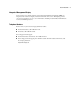
3-64 Compaq ProLiant ML370 Maintenance and Service Guide Remote Service Features Compaq servers have the following management features that you can access through a modem or a network: Table 3-23 Compaq Servers Remote Management Features Feature Description Service Session Provides remote access to all the utilities on the Compaq system partition, including Diagnostics utilities, Inspect, ROMPaq, Drive Array Advanced Diagnostics (DAAD), and the System Configuration Utility.
Diagnostics and Troubleshooting ROMPaq Disaster Recovery The following option should be utilized by any server that does not have a valid ROM image. IMPORTANT: This operation should be performed on a server with redundant ROM ONLY IF both ROM images have been corrupted. If only one image is corrupted, read the following section, “Redundant ROM Image Recovery,” for complete instructions. 1. Build a fresh ROMPaq diskette, using the latest version for the server involved.
3-66 Compaq ProLiant ML370 Maintenance and Service Guide 10. After successful completion of this process, a. Power down the server b. Remove the diskette. c. Reset configuration switches 1, 4, 5 and 6. (Refer to Configuration Switches Table within this section.) d. Power up the server as usual. After a failed ROMPaq, power down the server and repeat the above process.
Diagnostics and Troubleshooting Compaq Insight Manager Compaq Insight Manager is the Compaq application for easily managing network devices. Compaq Insight Manager delivers intelligent monitoring and alerting as well as visual control of the servers. In Compaq servers, every hardware subsystem, such as disk storage, system memory, and system processor, has a robust set of management capabilities.
3-68 Compaq ProLiant ML370 Maintenance and Service Guide ■ SNMP standards provide integration with other management products. ■ Flexible network conductivity supports multiple transport protocols including IPX, TCP/IP and PPP to operator over LANs, WANs, and modems.
Chapter 4 Connectors, Switches, and LED Indicators This chapter provides connector, switch, and LED indicator information for Compaq ProLiant ML370 Servers.
4-2 Compaq ProLiant ML370 Maintenance and Service Guide Compaq ProLiant ML370 System Board Components See Table 4-1 for the names of the Compaq ProLiant ML370 system board components. 1 2 3 4 5 6 7 8 9 10 22 11 12 21 13 14 20 19 15 17 18 16 Figure 4-1.
Connectors, Switches, and LED Indicators Rear Panel Components See Table 4-2 for the names of the Compaq ProLiant ML370 rear panel components. 10 1 2 3 11 4 5 6 7 8 9 Figure 4-2.
4-4 Compaq ProLiant ML370 Maintenance and Service Guide Switches The Compaq ProLiant ML370 Server has two switchbanks (SW1 and SW2) located on the system board. These switches are used to set the configuration of the server. The SW1 switch is used as a system identification switch, and the setting is pre-set in the factory. Do not change these settings. Incorrectly set switches may result in damage to the server. 1 on 2 1 2 3 4 5 6 Figure 4-3.
Connectors, Switches, and LED Indicators SW1 – System Identification Switch Settings The processor configuration switchbank (SW1) is an eight-position switch that is used for processor configuration. Figure 4-3 shows the position of the SW1 switchbank on the system board. Positions are reserved. CAUTION: Do not adjust the settings of the system identification switch.
4-6 Compaq ProLiant ML370 Maintenance and Service Guide LED Indicators This section contains graphics and tables showing LED indicator locations and functions. Front Panel Figure 4-4 and Table 4-5 identify the front panel LED indicators. 1 2 3 4 Figure 4-4.
Connectors, Switches, and LED Indicators RJ-45 Connector Figure 4-5 and Table 4-6 show the location and a description of the RJ-45 connector LED indicators. 1 2 Figure 4-5.
4-8 Compaq ProLiant ML370 Maintenance and Service Guide System Board Figure 4-6 and Table 4-7 show the location and meaning of the indicators. 1 2 3 4 5 6 Figure 4-6.
Connectors, Switches, and LED Indicators Riser Board Figure 4-7 and Table 4-8 show the location and meaning of the riser board indicator. 1 1 Figure 4-7.
Chapter 5 Physical and Operating Specifications This chapter provides operating and performance specifications for the Compaq ProLiant ML370 Server components: ■ System Unit ■ Power Supply ■ Redundant Power Supply ■ Dual Inline Memory Modules ■ 1.
5-2 Compaq ProLiant ML370 Maintenance and Service Guide System Unit Table 5-1 System Unit Specifications Dimensions Height (without feet) 45.52 cm (17.9 inches) Depth 57.58 cm (22.67 inches) Width 22.43 cm (8.83 inches) Weight (no hard drive installed) 22.
Physical and Operating Specifications Power Supply Table 5-2 Power Supply Specifications Input specifications Rated input voltage 100 – 240 VAC Rated input frequency 50 to 60 Hz Rated input current 6 A (110 V) to 3 A (220 V) Rated input power 550 W BTU/hr 1880 Output power Steady state power 325 W Maximum peak power 350 W Ambient temperature range Operating 10° to 35° C (50° to 95° F) Shipping -30° to 50° C (-22° to 122° F) Relative Humidity Operating 8% to 90% Nonoperating 5% to 95%
5-4 Compaq ProLiant ML370 Maintenance and Service Guide Redundant Power Supply Table 5-3 Redundant Power Supply Specifications Input specifications Rated input voltage 100 to 240 VAC Rated input frequency 50 to 60 Hz Rated input current 8 A (110 V) to 4 A (220 V) Rated input power 728 W BTU/hr 2490 Output power Steady state power 400 W Maximum peak power 445 W Ambient temperature range Operating 10° to 35° C (50° to 95° F) Shipping -30° to 50° C (-22° to 122° F) Relative Humidity Operati
Physical and Operating Specifications Dual Inline Memory Modules (DIMM) Table 5-4 DIMM Specifications Size 64-, 128-, 256-, 512 MB, or 1 GB Speed 133 MHz Type Registered ECC DIMMs; SDRAM 1.44-MB Diskette Drive Table 5-5 1.44-MB Diskette Drive Specifications Size 3 ½ inches LED indicators (front panel) Green Read/write capacity per diskette (high/low density) 1.
5-6 Compaq ProLiant ML370 Maintenance and Service Guide IDE CD-ROM Drive Table 5-6 IDE CD-ROM Drive Specifications Applicable disk CD-ROM (modes 1 and 2); mixed mode (audio and data combined); CD-DA; Photo CD (single/multiple-session), CD-XA ready; CDi ready Capacity 540 MB (mode 1, 12 cm) 650 MB (mode 2, 12 cm) Block size 2048 bytes (mode 1) 2336 bytes (mode 2) 2352 bytes (CD-DA) 2328 bytes (CD-XA) Dimensions Height 42.9 mm (1.68 inches) Depth 150.1 mm (5.85 inches) Width 208.0 mm (8.
Physical and Operating Specifications Compaq Wide Ultra2 Hot-Plug SCSI Hard Drives Table 5-7 Compaq Wide Ultra2 Hot-Plug SCSI Hard Drive Specifications Item 9.1-GB 7200 RPM 9.1-GB 10K RPM 18.2-GB 7200 RPM 18.2-GB 10K RPM Capacity 9100.0 MB 9100.0 MB 18209.8 MB 18209.8 MB Height Third, 1 inch Third, 1 inch Third, 1 inch Third, 1 inch Size 3.5 inches 3.5 inches 3.5 inches 3.
5-8 Compaq ProLiant ML370 Maintenance and Service Guide Integrated Dual Channel SCSI Controller Table 5-8 Integrated Dual Channel SCSI Controller Specifications Drives supported Up to 15 SCSI devices per channel Data transfer method 32-bit, 33-MHz PCI bus master SCSI channel transfer rate 160 MB/s (80 MB/s per channel) Maximum transfer rate per PCI bus (peak) 133 MB/s SCSI termination Active termination SCSI connectors 1 external 68-pin, 2 internal 68-pin RAID functionality Dual channel RAID
Index A access panels large access part number 1-3 removing 2-9 removing, illustrated 2-9 replacing 2-9 right side part number 1-3 removing 2-11 removing, illustrated 2-11 replacing 2-11 small access part number 1-3 removing 2-10 removing, illustrated 2-10 replacing 2-10 ADU accessing 3-5 description 3-3, 3-35 executing 3-6 starting 3-35 Array Configuration Utility accessing 3-5 accessing from System Configuration 3-5 executing 3-6 Array Diagnostic utility See ADU ART, assembly version 3-62 ASR-2 See Autom
2 Compaq ProLiant ML370 Maintenance and Service Guide software error recovery 3-53 recovery boot option 3-53 recovery time-out 3-53 standby recovery server option 3-53 server port 3-53 time-out 3-53 thermal shutdown 3-53 timer 3-54 unattended recovery 3-51 UPS shutdown 3-53 UPS shutdown threshold 3-53 B backplane removing 2-35 removing, illustrated 2-35 replacing 2-35 backplane board part number 1-5 baffle, part numbers 1-6 battery installing 2-38 part number 1-5 removing, illustrated 2-38 beeps, during
Index remote maintenance 3-68 viewing the event list 3-47 Compaq Integrated Remote Console features 3-54 Compaq Integrated Smart Array Controller location, identified 4-2 part number 1-7 upgrade module removing 2-37 removing, illustrated 2-37 replacing 2-37 Compaq Survey utility description 3-2 installing 3-2 Compaq System Reference Library 3-50 Comprehensive Insight Management, defined 3-67 conflict, resolving 3-3 Correctable Memory Logs See IML country kit, part number 1-6 CPU fan See fans, CPU Critical
4 Compaq ProLiant ML370 Maintenance and Service Guide transporting parts safely 2-2 workstation recommendations 2-2 environmental recovery 3-51 error 101 through 105 3-8 101 through 199 3-27 1101 through 1199 3-31 1151 through 1611 3-11 1201 through 1299 3-32 122-XX 3-27 123-XX 3-27 1612 through 1622 3-12 162 through 164 3-8 1702 through 1731 3-13 172 through 180 3-8 1740 through 1767 3-15 1768 through 1773 3-16 1774 through 1779 3-17 1780 through 1789 3-19 1790 through 1799 3-23 1797 through 1799 3-25 19
Index correctable error threshold exceeded 3-48, 3-49 Diagnostic Error 3-60 dirty data 3-36 disable command issued 3-39 drive (bay) drive X failed 3-40 drive X inadvertently replaced 3-40 firmware needs upgrading 3-39 insufficient capacity 3-39 invalid M&P stamp 3-39 loose cable 3-39 needs replacing 3-40 replacement drive 3-39 replacement drive marked OK 3-40 undergoing drive recovery 3-40 upload code not readable 3-40 Drive (bay) X is non-Compaq supplied 3-41 drive monitoring features unobtainable 3-40 no
6 Compaq ProLiant ML370 Maintenance and Service Guide power AC overload 3-49 power module failure 3-49 not redundant 3-49 power supply failure 3-49 inserted 3-49 not redundant 3-49 removed 3-49 system configuration battery low 3-49 system crash 3-49 system lockup 3-49 uncorrectable error 3-48, 3-49 event list See also IMD defined 3-48 printing 3-47 viewing 3-47 event messages, defined 3-48 events log description 3-3 viewing 3-3 expansion slots, illustrated 4-3 exploded view mechanical parts 1-2 system com
Index Compaq Integrated Smart Array Controller upgrade module, removing 2-37 CPU fan, removing 2-21 DIMM slots on system board 2-31 diskette drive, removing 2-17 drive cage, removing 2-15 drives and related components 2-12 feet, removing 2-8 front bezel plate, removing 2-7 front bezel, removing 2-6 front panel LED indicators 4-6 front plate, replacing 2-7 hard drive blank, removing 2-18 hard drive, removing 2-19 I/O expansion board, removing 2-27 I/O expansion slot cover, removing 2-26 I/O fan, removing 2-
8 Compaq ProLiant ML370 Maintenance and Service Guide test error codes 3-29 kits data cable, part number 1-5 hardware, part number 1-6 plastics, part number 1-6 power cable, part number 1-6 rack conversion, part number 1-6 signal cable, part number 1-6 L large access panel See panels, large access laser product label, illustrated 2-2 LEDs auxiliary power, identified 4-9 CD-ROM drive power, identified 4-6 diskette drive power, identified 4-6 front panel, illustrated 4-6 interlock, identified 4-8 NIC activ
Index right side part number 1-3 removing 2-11 removing, illustrated 2-11 replacing 2-11 small access part number 1-3 removing 2-10 removing, illustrated 2-10 replacing 2-10 parallel connector, illustrated 4-3 parallel printer, test error codes 3-29 part numbers backplane board 1-5 baffle 1-6 battery, 3V lithium 1-5 CD-ROM drive 1-5 chassis 1-3 country kit 1-6 data cable kit 1-5 diskette drive 1-5 fans CPU 1-5 I/O 1-5 feet 1-3 front bezel 1-3 front bezel plate 1-3 hard drive blank 1-6 hard drives 1-5 illus
10 Compaq ProLiant ML370 Maintenance and Service Guide R S rack conversion kit, part number 1-6 rack front plate See front plate rack warnings 2-4 Rapid Recovery Engine, enabling 3-50 rapid recovery services 3-50 rear panel components, illustrated 4-3 recovery attended 3-51 automatic 3-50 environmental 3-51 from software error 3-51 rapid recovery services 3-50 unattended 3-51 redundant power supply specifications 5-4 Remote Management, defined 3-67 remote service features, defined 3-64 Remote Utilities,
Index standby recovery server option 3-53 server port 3-53 time-out 3-53 static electricity See electrostatic discharge storage automatic reconstruction, defined 3-63 storage fault recovery tracking, defined 3-63 Survey utility, viewing 3-47 switch settings, obtaining 3-3 switchbanks, identified 4-4 switches SW1 defined 4-4, 4-5 illustrated 4-4 SW2 defined 4-4, 4-5 illustrated 4-4 symbols used in equipment 2-2 used in text vii system board components, identified 4-2 components, illustrated 4-2 part number
12 Compaq ProLiant ML370 Maintenance and Service Guide Riser Board Expansion Slots 2-25 Riser Board LED Indicator 4-9 RJ-45 Connected LED Indicators 4-7 SCSI Hard Drive Test Error Codes 3-33 SCSI Tape Drive Test Error Codes 3-34 SCSI/IDE CD_ROM Drive Test Error Codes 3-33 SDRAM DIMM Slot Locations 2-31 Serial Test Error Codes 3-31 System Board Components 4-2 System Board LED Indicators 4-8 System Board Switches 4-4 System Components Spare Parts List 1-5 System Configuration Switch Settings (SW2) 4-5 Syste
Index Firmware Upgrade, accessing 3-5 Health Driver 3-54 IML Management utility, defined 3-47 Inspect accessing 3-2, 3-26 description 3-2, 3-4 printing Inspect listing 3-4 running 3-4 Integrated Management Log description 3-3 Remote Utilities, accessing 3-26 ROMPaq Firmware Upgrade, accessing 3-5 running from diskette 3-6 running from SmartStart and Support Software CD 3-6 starting from ASR-2 3-56 Survey, defined 3-47 System Configuration accessing 3-5 booting from pager 3-56 description 3-3 executing 3-6