b Maintenance and Service Guide Compaq Presario V5000 Notebook PC Document Part Number: 407511-002 June 2006 This guide is a troubleshooting reference used for maintaining and servicing the computer. It provides comprehensive information on identifying computer features, components, and spare parts; troubleshooting computer problems; and performing computer disassembly procedures.
© Copyright 2006 Hewlett-Packard Development Company, L.P. Microsoft and Windows are U.S. registered trademarks of Microsoft Corporation. AMD, Sempron, Turion, and combinations thereof, are trademarks of Advanced Micro Devices, Inc. Bluetooth is a trademark owned by its proprietor and used by Hewlett-Packard Company under license. SD Logo is a trademark of its proprietor. The information contained herein is subject to change without notice.
Contents 1 Product Description 1.1 1.2 1.3 1.4 1.5 Features . . . . . . . . . . . . . . . . . . . . . . . . . . . . . . . . . . . 1–2 Resetting the Computer. . . . . . . . . . . . . . . . . . . . . . . 1–4 Power Management. . . . . . . . . . . . . . . . . . . . . . . . . . 1–5 External Components . . . . . . . . . . . . . . . . . . . . . . . . 1–6 Design Overview. . . . . . . . . . . . . . . . . . . . . . . . . . . 1–20 2 Troubleshooting 2.1 Computer Setup. . . . . . . . . . . . . . . . . . . . . . . . .
Contents 3 Illustrated Parts Catalog 3.1 3.2 3.3 3.4 3.5 3.6 3.7 3.8 Serial Number Location . . . . . . . . . . . . . . . . . . . . . . 3–1 Computer Major Components. . . . . . . . . . . . . . . . . . 3–2 Display Assembly Subcomponents. . . . . . . . . . . . . 3–12 Plastics Kit . . . . . . . . . . . . . . . . . . . . . . . . . . . . . . . 3–14 Cable Kit . . . . . . . . . . . . . . . . . . . . . . . . . . . . . . . . . 3–15 Mass Storage Devices . . . . . . . . . . . . . . . . . . . . . . .
Contents 5 Removal and Replacement Procedures 5.1 Serial Number . . . . . . . . . . . . . . . . . . . . . . . . . . . . . . 5–2 5.2 Disassembly Sequence Chart . . . . . . . . . . . . . . . . . . 5–3 5.3 Preparing the Computer for Disassembly . . . . . . . . . 5–5 5.4 Hard Drive. . . . . . . . . . . . . . . . . . . . . . . . . . . . . . . . . 5–7 5.5 Computer Feet. . . . . . . . . . . . . . . . . . . . . . . . . . . . . 5–11 5.6 Memory Module . . . . . . . . . . . . . . . . . . . . . . . . . . . 5–12 5.
Contents 6 Specifications A Screw Listing B Software Update and Recovery C Display Component Recycling D Connector Pin Assignments E Power Cord Set Requirements Index vi Maintenance and Service Guide
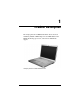
1 Product Description The Compaq Presario V5000 Notebook PC offers advanced modularity, Mobile AMD Sempron™ and AMD Turion™ 64 Mobile Technology processors, and extensive multimedia support.
Product Description 1.1 Features references are made throughout this Maintenance ✎ Numerous and Service Guide to “full-featured” and “defeatured” computer models. A model is considered to be full-featured if it has 3 Universal Serial Bus ports and the following components: ■ PC Card slot ■ IEEE 1394 port ■ Memory Reader A model is considered to be defeatured if it has only 2 Universal Serial Bus ports and none of the components listed above. 1–2 ■ AMD Turion 64 ML-40 (2.2-GHz), ML-37 (2.
Product Description ■ TouchPad pointing device, including dedicated horizontal and vertical scroll regions ■ Integrated 10Base-T/100Base-TX Ethernet local area network (LAN) network interface card (NIC) with RJ-45 jack ■ Integrated high-speed 56K modem with RJ-11 jack ■ Integrated wireless support for Mini PCI IEEE 802.
Product Description ■ Connectors: ❏ Audio-in (microphone) ❏ Audio-out (headphone) ❏ Memory Reader (select models only) ❏ Expansion port 2 ❏ ExpressCard slot ❏ External monitor ❏ IEEE 1394 (select models only) ❏ PC Card (select models only) ❏ Power ❏ RJ-11 (modem) ❏ RJ-45 (network) ❏ S-Video-out ❏ Universal Serial Bus (USB) v. 2.0 (2 or 3 ports, varying by computer model) 1.2 Resetting the Computer If the computer you are servicing has an unknown password, follow these steps to clear the password.
Product Description 3. Wait approximately 5 minutes. 4. Replace the RTC battery and reassemble the computer. 5. Connect AC power to the computer. Do not reinsert any batteries at this time. 6. Turn on the computer. All passwords and CMOS settings have been cleared. 1.3 Power Management The computer comes with power management features that extend battery operating time and conserve power.
Product Description 1.4 External Components The external components on the front of the computer are shown below and described in Table 1-1.
Product Description Table 1-1 Front Components Item Component Function 1 Power light ■ On: Computer is turned on. ■ Off: Computer is off or in hibernation. ■ Blinking: Computer is in standby. 2 Battery light ■ On: A battery is charging or is close to full charge capacity. ■ Off: If the computer is plugged into an external power source, the light is turned off when all batteries in the computer are fully charged.
Product Description The external components on the right side of the computer are shown below and described in Table 1-2. Right-Side Components Table 1-2 Right-Side Components Item Component Function 1 Audio-out (headphone) jack Connects an optional headphone or powered stereo speakers. Also connects the audio function of an audio/video device, such as a television or VCR. 2 Audio-in (microphone) jack Connects an optional stereo microphone. 3 ExpressCard slot Supports an optional ExpressCard.
Product Description The external components on the rear panel of the computer are shown below and described in Table 1-3. Rear Panel Components Table 1-3 Rear Panel Components Item Component Function 1 Battery bay Holds a battery. 2 Vent Provides airflow to cool internal components. To prevent overheating, do not obstruct vents. Do not allow a hard surface, such as a printer, or a soft surface, such as pillows or thick rugs or clothing, to block airflow.
Product Description The external components on the left side of the computer are shown below and described in Table 1-4. Left-Side Components Table 1-4 Left-Side Components Item Component Function 1 Security cable slot Attaches an optional security cable to the computer. purpose of security solutions is ✎ The to act as a deterrent. These solutions do not prevent the product from being mishandled or stolen. 2 Monitor port Connects an optional VGA monitor or projector.
Product Description Table 1-4 Left-Side Components (Continued) Item Component Function 4 RJ-45 (network) jack Connects a network cable (not included). 5 Expansion port 2 Connects the computer to an optional docking device. computer has only one ✎ The expansion port. The term expansion port 2 describes the type of expansion port. 6 USB ports (2) Connect optional USB devices.
Product Description The standard keyboard components of the computer are shown below and described in Table 1-5.
Product Description Table 1-5 Standard Keyboard Components Item Component Function 1 F1 to F12 keys (12) Perform system and application tasks. When combined with Fn, function keys perform additional tasks as hotkeys. 2 caps lock key Enables caps lock and turns on the caps lock light. 3 Fn key Combines with other keys to perform system tasks as hotkeys. For example, pressing Fn+f7 decreases screen brightness. 4 Windows logo key Displays the Microsoft Windows Start menu.
Product Description The computer top components are shown below and described in Table 1-6.
Product Description Table 1-6 Top Components Item Component Function 1 caps lock light On: Caps lock is enabled. 2 Wireless button Turns the wireless functionality on or off, but does not create a wireless connection. establish a wireless connection, ✎ To a wireless network must already be set up. 3 Power button When the computer is ■ Off, press to turn on the computer. ■ On, press to enter hibernation. ■ In standby, briefly press to exit standby.
Product Description The computer TouchPad components are shown below and described in Table 1-7.
Product Description Table 1-7 TouchPad Components Item Component Function 1 TouchPad Moves the pointer and selects or activates items on the screen. Can be set to perform other mouse functions, such as scrolling, selecting, and double-clicking. 2 TouchPad horizontal scroll zone Scrolls left or right. 3 Left and right TouchPad buttons Function like the left and right buttons on an external mouse. 4 TouchPad vertical scroll zone Scrolls up or down.
Product Description The external components on the bottom of the computer are shown below and described in Table 1-8. Bottom Components Table 1-8 Bottom Components Item Component Function 1 Optical drive Supports an optical disc, such as a CD or DVD. 2 Labels area Contains the serial number and other information labels. 3 Battery release latch Releases a battery from the battery bay. 4 Battery bay Holds a battery.
Product Description Table 1-8 Bottom Components (Continued) Item Component Function 5 Vents (2) Provide airflow to cool internal components. To prevent overheating, do not obstruct vents. Do not allow a hard surface, such as a printer, or a soft surface, such as pillows or thick rugs or clothing, to block airflow. Ä 6 Memory/Mini PCI module compartment cover ■ Contains 2 memory module slots that support replaceable memory modules. The number of preinstalled memory modules varies by computer model.
Product Description 1.5 Design Overview This section presents a design overview of key parts and features of the computer. Refer to Chapter 3, “Illustrated Parts Catalog,” to identify replacement parts, and Chapter 5, “Removal and Replacement Procedures,” for disassembly steps.
2 Troubleshooting Å WARNING: Only authorized technicians trained by HP should repair this equipment. All troubleshooting and repair procedures are detailed to allow only subassembly-/module-level repair. Because of the complexity of the individual boards and subassemblies, do not attempt to make repairs at the component level or modifications to any printed wiring board. Improper repairs can create a safety hazard.
Troubleshooting 2. Select the File, Security, Diagnostics, or System Configuration menu. 3. To close Computer Setup and restart the computer: ❏ Select File > Save changes and exit, and then press enter. – or – ❏ Select File > Ignore changes and exit, and then press enter. – or – ❏ Select File > Restore defaults, and then press enter. 4. When you are prompted to confirm your action, press f10.
Troubleshooting Selecting from the Security Menu Table 2-2 Security Menu Select To Do This Setup Password Enter, change, or delete an Setup password. Power-On Password Enter, change, or delete a power-on password. Password Options (Password options can be selected only when a power-on password has been set.) Enable/disable: ■ Stringent security. ■ Requirement of password on restart. DriveLock Passwords Enable/disable DriveLock; change a DriveLock user or master password.
Troubleshooting Selecting from the Diagnostics Menu Table 2-3 Diagnostics Menu Select To Do This HDD Self-Test Options Run a quick comprehensive self test on hard drives in the system that support the test features.
Troubleshooting Selecting from the System Configuration Menu Table 2-4 System Configuration Menu Select To Do This Language Change the Computer Setup language. Boot Options Enable/disable MultiBoot, which sets a startup sequence that can include most bootable devices and media in the system. Device Configurations Enable/disable: ■ Swap Fn/Ctrl keys. ■ USB legacy support. ■ BIOS DMA data transfers. ■ Fan Always on while on AC Power. ■ Data Execution Prevention. ■ LAN Power save.
Troubleshooting 2.2 Troubleshooting Flowcharts Table 2-5 Troubleshooting Flowcharts Overview Flowchart Description 2.1 “Flowchart 2.1—Initial Troubleshooting” 2.2 “Flowchart 2.2—No Power, Part 1” 2.3 “Flowchart 2.3—No Power, Part 2” 2.4 “Flowchart 2.4—No Power, Part 3” 2.5 “Flowchart 2.5—No Power, Part 4” 2.6 “Flowchart 2.6—No Video, Part 1” 2.7 “Flowchart 2.7—No Video, Part 2” 2.8 “Flowchart 2.8—Nonfunctioning Docking Device (if applicable)” 2.9 “Flowchart 2.
Troubleshooting Flowchart 2.1—Initial Troubleshooting Begin troubleshooting. N Go to Is there power? “Flowchart 2.2—No Power, Part 1.” Y N Check LED board, speaker connections. Beeps, LEDs, or error messages? N Y Go to All drives working? N Go to Is there video? (no boot) Y “Flowchart 2.6—No Video, Part 1.” N Keyboard/ pointing device working? Y N Go to Is the OS loading? N Go to Is there sound? Y “Flowchart 2.9—No Operating System (OS) Loading.” Y “Flowchart 2.15—No Audio, Part 1.
Troubleshooting Flowchart 2.2—No Power, Part 1 No power (power LED is off). Remove from docking device (if applicable). N N Power up on battery power? Go to Power up on battery power? Reset power.* “Flowchart 2.3—No Power, Part 2.” Y Y N N Power up on AC power? Power up on AC power? Reset power.* Y Go to “Flowchart 2.4—No Power, Part 3.” Y Y Power up in docking device? Done *NOTES N 1. Reset the power cables in the docking device and at the AC outlet. 2.
Troubleshooting Flowchart 2.3—No Power, Part 2 Continued from “Flowchart 2.2—No Power, Part 1.” Visually check for debris in battery socket and clean if necessary. Y Power on? Done N Check battery pack by recharging it, moving it to another computer, N Replace power supply (if applicable). Power on? Y N Go to Done Power on? “Flowchart 2.4—No Power, Part 3.
Troubleshooting Flowchart 2.4—No Power, Part 3 Continued from “Flowchart 2.3—No Power, Part 2.” Plug directly into AC outlet. Y Power LED on? Done N Reseat AC adapter in computer and at power source. Y Done Power on? N External N Try different outlet. Power outlet active? Y Internal or external AC adapter? Replace external AC adapter. N Internal Go to “Flowchart 2.5—No Power, Part 4.” Replace power cord.
Troubleshooting Flowchart 2.5—No Power, Part 4 Continued from “Flowchart 2.4—No Power, Part 3.” Open computer. Y Loose or damaged parts? N Reseat loose components and boards and replace damaged items. Close computer and retest. N Power on? Replace the following items (if applicable). Check computer operation after each replacement: 1. Internal DC-DC converter* 2. Internal AC adapter 3. Processor board* 4. System board* *NOTE: Replace these items as a set to prevent shorting out among components.
Troubleshooting Flowchart 2.6—No Video, Part 1 No video. Docking Device Go to Stand-alone or docking device? *NOTE: To change from internal to external display, use the hotkey combination. “Flowchart 2.7—No Video, Part 2.” Stand-alone Internal or external display*? Y Adjust brightness. A Adjust brightness. Press lid switch to ensure operation. Y Video OK? Done N Internal External Video OK? Y Done N Video OK? Done N Replace the following one at a time. Test after each replacement. 1.
Troubleshooting Flowchart 2.7—No Video, Part 2 Continued from “Flowchart 2.6—No Video, Part 1.” Remove computer from docking device, if connected. Adjust display brightness. Check brightness of external monitor. N Y Go to “A” in “Flowchart 2.6—No Video, Part 1.” Video OK? Y Video OK? Done N Check that computer is properly seated in docking device, for bent pins on cable, and for monitor connection. Try another external monitor.
Troubleshooting Flowchart 2.8—Nonfunctioning Docking Device (if applicable) Nonfunctioning docking device. Reset power cord in docking device and power outlet. Check voltage setting on docking device. Reset monitor cable connector at docking device. Reinstall computer into docking device. Y Docking device operating? N Y Docking device operating? Done Done N Replace docking device. 2–14 Test replacement docking device with new computer.
Troubleshooting Flowchart 2.9—No Operating System (OS) Loading No OS loading.* Reset power cord in docking device and power outlet. No OS loading from hard drive, go to “Flowchart 2.10—No OS Loading, Hard Drive, Part 1.” No OS loading from diskette drive, go to “Flowchart 2.13—No OS Loading, Diskette Drive.” No OS loading from CD-ROM or DVD-ROM drive, go to “Flowchart 2.14—No OS Loading, Optical Drive.” No OS loading from network, go to “Flowchart 2.20—No Network/Modem Connection.
Troubleshooting Flowchart 2.10—No OS Loading, Hard Drive, Part 1 OS not loading from hard drive. Y Nonsystem disk message? N Go to “Flowchart 2.11—No OS Loading, Hard Drive, Part 2.” Reseat external hard drive. Y OS loading? Done N N Boot from CD? N Y Boot from diskette? Check the Setup utility for correct booting order. Y Change boot priority through the Setup Utility and reboot. N Boot from hard drive? N Y Boot from hard drive? Done Y 2–16 Go to “Flowchart 2.
Troubleshooting Flowchart 2.11—No OS Loading, Hard Drive, Part 2 Continued from “Flowchart 2.10—No OS Loading, Hard Drive, Part 1.” Reseat hard drive. N 1. Replace hard drive. 2. Replace system board. CD or diskette in drive? Y Hard drive accessible? Y Done N Remove diskette and reboot. Run FDISK. Y Boot from hard drive? N Done N Hard drive partitioned? Y N Y N Go to “Flowchart 2.13—No OS Loading, Diskette Drive.
Troubleshooting Flowchart 2.12—No OS Loading, Hard Drive, Part 3 Continued from “Flowchart 2.11—No OS Loading, Hard Drive, Part 2.” N System files on hard drive? Install OS and reboot. Y Y Y Virus on hard drive? OS loading from hard drive? Clean virus. N Done N Y Run SCANDISK and check for bad sectors. Diagnostics on diskette? Replace hard drive. N N Can bad sectors be fixed? Run diagnostics and follow recommendations. Replace hard drive. Y N Boot from hard drive? Fix bad sectors.
Troubleshooting Flowchart 2.13—No OS Loading, Diskette Drive Y OS not loading from diskette drive. Reseat diskette drive. OS loading? Done N Y N Bootable diskette in drive? Nonsystem disk message? N Y N Check diskette for system files. Try different diskette. Go to Boot from another device? “Flowchart 2.17—Nonfunctioning Device.” Y Y N Diskette drive enabled in the Setup Utility? 1. Replace diskette drive. 2. Replace system board. Nonsystem disk error? Enable drive and cold boot computer.
Troubleshooting Flowchart 2.14—No OS Loading, Optical Drive Y No OS loading from CD-ROM or DVD-ROM drive. N Install bootable disc and reboot computer. Bootable disc in drive? Disc in drive? Y N Install bootable disc. Try another bootable disc. Y Boots from CD or DVD? Done N Y Boots from CD or DVD? Reseat drive. Done N N Booting from another device? Y Y Booting order correct? N Go to “Flowchart 2.17—Nonfunctioning Device.” Reset the computer. Refer to Go to Section 1.
Troubleshooting Flowchart 2.15—No Audio, Part 1 Y Turn up audio internally or externally. No audio. Audio? Done N Y Computer in docking device (if applicable)? N Go to Internal audio? Undock N “Flowchart 2.16—No Audio, Part 2.” Y Go to Replace the docking device. “Flowchart 2.16—No Audio, Part 2.” Y Go to “Flowchart 2.17—Nonfunctioning Device.
Troubleshooting Flowchart 2.16—No Audio, Part 2 Continued from “Flowchart 2.15—No Audio, Part 1.” N Audio driver in OS configured? Reload audio drivers. Y N Correct drivers for application? Load drivers and set configuration in OS. Y Connect to external speaker. N Audio? Y Replace audio board and speaker connections in computer (if applicable). Y Audio? Done N 1. Replace internal speakers. 2. Replace audio board (if applicable). 3. Replace system board.
Troubleshooting Flowchart 2.17—Nonfunctioning Device Nonfunctioning device. Reseat device. Unplug the nonfunctioning device from the computer and inspect cables and plugs for bent or broken pins or other damage. Y Clear CMOS. Fix or replace broken item. Any physical device detected? N Reattach device. Close computer, plug in power, and reboot. Go to “Flowchart 2.9—No Operating System (OS) Loading.” Replace hard drive. N Device boots properly? N Replace NIC.
Troubleshooting Flowchart 2.18—Nonfunctioning Keyboard Keyboard not operating properly. Connect computer to good external keyboard. N External device works? Replace system board. Y Reseat internal keyboard connector (if applicable). N Replace internal keyboard or cable. OK? Y Y Done OK? Done N Replace system board.
Troubleshooting Flowchart 2.19—Nonfunctioning Pointing Device Pointing device not operating properly. Connect computer to good external pointing device. N Replace system board. External device works? Y Reseat internal pointing device connector (if applicable). N Replace internal pointing device or cable. OK? Y Y Done OK? Done N Replace system board.
Troubleshooting Flowchart 2.20—No Network/Modem Connection No network or modem connection. N Network or modem jack active? Replace jack or have jack activated. Y Y Connect to nondigital line. Digital line? N Y N NIC/modem configured in OS? Reload drivers and reconfigure. Done OK? N Y Disconnect all power from the computer and open. Replace the NIC/modem (if applicable). Y Reseat NIC/modem (if applicable). OK? Done N Replace system board.
3 Illustrated Parts Catalog This chapter provides an illustrated parts breakdown and a reference for spare part numbers. 3.1 Serial Number Location When ordering parts or requesting information, provide the computer serial number and model number located on the bottom of the computer.
Illustrated Parts Catalog 3.
Illustrated Parts Catalog Table 3-1 Spare Parts: Computer Major Components Spare Part Number Item Description 1 Display assemblies (include display cable, wireless antenna transceivers, and antenna cables) 15.4-inch, WXGA with BrightView 15.4-inch, WXGA antiglare 407842-001 407840-001 Refer to Section 3.3, “Display Assembly Subcomponents,” for ✎ display assembly internal component spare part number information.
Illustrated Parts Catalog Computer Major Components 3–4 Maintenance and Service Guide
Illustrated Parts Catalog Table 3-1 Spare Parts: Computer Major Components (Continued) Item 6a 6b 6c Description Spare Part Number Cable Kit, 407775-001 Includes: Bluetooth module cable USB/audio board cable Power connector cable power connector cable is also available using spare part ✎ The number 415564-001.
Illustrated Parts Catalog Computer Major Components 3–6 Maintenance and Service Guide
Illustrated Parts Catalog Table 3-1 Spare Parts: Computer Major Components (Continued) Item 11a 11b 11c Description Spare Part Number Plastics Kit 407779-001 Includes: PC Card slot bezel ExpressCard slot bezel Hard drive cover (includes 2 captive screws) hard drive cover is also available using spare part number ✎ The 419328-001.
Illustrated Parts Catalog Computer Major Components 3–8 Maintenance and Service Guide
Illustrated Parts Catalog Table 3-1 Spare Parts: Computer Major Components (Continued) Item Description Spare Part Number 15 Heat sink (includes thermal paste) Thermal paste 403827-001 407817-001 16 Fan assembly 407808-001 17 USB/audio board (includes USB/audio board cable) For use with full-featured models For use with defeatured models 417027-001 417028-001 18 Speakers 407785-001 19 Base enclosures For use with full-featured models For use with defeatured models 20 415493-001 415494-001
Illustrated Parts Catalog Computer Major Components 3–10 Maintenance and Service Guide
Illustrated Parts Catalog Table 3-1 Spare Parts: Computer Major Components (Continued) Spare Part Number Item Description 22 Memory modules, 1-DIMM SD Memory Cards (not illustrated) 1024 MB 512 MB 256 MB 512 MB 256 MB 403800-001 403799-001 407843-001 23 RTC battery (includes tape) 24 Mini PCI communications modules 407316-001 403573-001 407816-001 802.11a/b/g WLAN module for use in North America 802.11a/b/g WLAN module for use in the rest of the world 403791-001 403792-001 802.
Illustrated Parts Catalog 3.
Illustrated Parts Catalog Table 3-2 Display Assembly Subcomponents Spare Part Number Information Item 1a 1b Description Display Plastics Kit Includes: ■ Display bezel 407793-001 ■ Display enclosure ■ Display hinge base covers (not illustrated) ■ Display hinge covers (not illustrated) Display Hinge Kit Includes: ■ Display hinges ■ Display release hook (not illustrated) 407797-001 3 Display inverter board 407800-001 4 Display Panel Kit (includes display panel cable) 15.
Illustrated Parts Catalog 3.4 Plastics Kit Table 3-3 Plastics Kit Spare Part Number Information Item Description Spare Part Number Plastics Kit 407779-001 1 Includes: Memory/Mini PCI module compartment cover (includes 2 captive screws, secured by C-clips) 2 Hard drive cover (includes 2 captive screws, secured by C-clips) hard drive cover is also available using spare part number ✎ The 419328-001.
Illustrated Parts Catalog 3.5 Cable Kit Table 3-4 Cable Kit Spare Part Number Information Item Description Spare Part Number Cable Kit 407775-001 1 Includes: TouchPad cable 2 Bluetooth module cable 3 USB/audio board cable 4 Modem connector cable 5 Power connector cable power connector cable is also available using spare part ✎ The number 415564-001.
Illustrated Parts Catalog 3.
Illustrated Parts Catalog Table 3-5 Mass Storage Devices Spare Part Number Information Spare Part Number Item Description 1 Hard drives (include frame and connector) 5400-rpm, 80-GB 2 407852-001 4200-rpm, 120-GB 4200-rpm, 100-GB 4200-rpm, 80-GB 4200-rpm, 60-GB 4200-rpm, 40-GB 407853-001 407851-001 410054-001 407850-001 407849-001 Optical drives DVD±RW and CD-RW Double-Layer Combo Drive DVD/CD-RW Double-Layer Combo Drive with LightScribe DVD/CD-RW Combo Drive 413101-001 413101-001 DVD±RW and CD-R
Illustrated Parts Catalog 3.
Illustrated Parts Catalog Table 3-6 Miscellaneous (Not Illustrated) Spare Part Information (Continued) Spare Part Number Description Power cords For use in: Australia 403811-011 Canada, French Canada, and the United States 403811-001 Denmark 403811-081 France, Germany, and Spain 403811-021 Israel 403811-BB1 The United Kingdom 403811-031 Switzerland 403811-111 Italy 403811-061 Screw Kit (includes the following screws; refer to Appendix A, “Screw Listing,” for more information on specificati
Illustrated Parts Catalog 3.8 Sequential Part Number Listing Table 3-7 Sequential Part Number Listing Spare Part Number Description 309674-001 USB travel mouse 364727-001 USB digital drive 371693-001 Wired headset with volume control 392557-001 802.11b/g WLAN Mini PCI communications module for use in North America 392557-002 802.11b/g WLAN Mini PCI communications module for use in the rest of the world 393578-001 AMD Turion 64 ML-37 (2.
Illustrated Parts Catalog Table 3-7 Sequential Part Number Listing (Continued) Spare Part Number Description 403811-021 Power cord for use internationally 403811-031 Power cord for use in the United Kingdom 403811-061 Power cord for use in Italy 403811-081 Power cord for use in Denmark 403811-111 Power cord for use in Switzerland 403811-BB1 Power cord for use in Israel 403827-001 Heat sink 407316-001 SD Memory Card 512-MB 407775-001 Cable Kit 407777-001 Label Kit 407779-001 Plastics
Illustrated Parts Catalog Table 3-7 Sequential Part Number Listing (Continued) Spare Part Number Description 407809-001 ExpressCard assembly 407812-001 TouchPad bracket 407816-001 RTC battery (includes tape) 407817-001 Thermal paste 407821-001 Bracket Kit 407823-001 Top cover for use with full-featured computers 407824-001 Top cover for use with defeatured computers 407827-001 Switch cover for use with full-featured computers 407828-001 Switch cover for use with defeatured computers 407
Illustrated Parts Catalog Table 3-7 Sequential Part Number Listing (Continued) Spare Part Number Description 407852-001 5400-rpm, 80-GB hard drive 407853-001 4200-rpm, 120-GB hard drive 407856-001 Keyboard for use in the United States 407856-031 Keyboard for use in the United Kingdom 407856-051 Keyboard for use in France 407856-061 Keyboard for use in Italy 407856-071 Keyboard for use in Spain 407856-081 Keyboard for use in Denmark 407856-091 Keyboard for use in Norway 407856-121 Keybo
Illustrated Parts Catalog Table 3-7 Sequential Part Number Listing (Continued) Spare Part Number Description 412176-001 DVB-T TV tuner antenna 413100-001 DVD/CD-RW Combo Drive 413101-001 DVD±RW and CD-RW Double-Layer Combo Drive 413102-001 DVD/CD-RW Double-Layer Combo Drive with LightScribe 415493-001 Base enclosure for use with full-featured computer models 415494-001 Base enclosure for use with defeatured computer models 415564-001 Power connector cable 417024-001 LED board 417027-001
4 Removal and Replacement Preliminaries This chapter provides essential information for proper and safe removal and replacement service.y 4.
Removal and Replacement Preliminaries 4.2 Service Considerations The following sections include some of the considerations that you should keep in mind during disassembly and assembly procedures. you remove each subassembly from the computer, place ✎ As the subassembly (and all accompanying screws) away from the work area to prevent damage. Plastic Parts Using excessive force during disassembly and reassembly can damage plastic parts. Use care when handling the plastic parts.
Removal and Replacement Preliminaries 4.3 Preventing Damage to Removable Drives Removable drives are fragile components that must be handled with care. To prevent damage to the computer, damage to a removable drive, or loss of information, observe the following precautions: ■ Before removing or inserting a hard drive, shut down the computer. If you are unsure whether the computer is off or in Hibernation, turn the computer on, and then shut it down through the operating system.
Removal and Replacement Preliminaries 4.4 Preventing Electrostatic Damage Many electronic components are sensitive to electrostatic discharge (ESD). Circuitry design and structure determine the degree of sensitivity. Networks built into many integrated circuits provide some protection, but in many cases, the discharge contains enough power to alter device parameters or melt silicon junctions.
Removal and Replacement Preliminaries 4.5 Packaging and Transporting Precautions Use the following grounding precautions when packaging and transporting equipment: ■ To avoid hand contact, transport products in static-safe containers, such as tubes, bags, or boxes. ■ Protect all electrostatic-sensitive parts and assemblies with conductive or approved containers or packaging. ■ Keep electrostatic-sensitive parts in their containers until the parts arrive at static-free workstations.
Removal and Replacement Preliminaries 4.6 Workstation Precautions Use the following grounding precautions at workstations: ■ Cover the workstation with approved static-shielding material (refer to Table 4-2, “Static-Shielding Materials”). ■ Use a wrist strap connected to a properly grounded work surface and use properly grounded tools and equipment. ■ Use conductive field service tools, such as cutters, screwdrivers, and vacuums.
Removal and Replacement Preliminaries 4.7 Grounding Equipment and Methods Grounding equipment must include either a wrist strap or a foot strap at a grounded workstation. ■ When seated, wear a wrist strap connected to a grounded system. Wrist straps are flexible straps with a minimum of one megohm ±10% resistance in the ground cords. To provide proper ground, wear a strap snugly against the skin at all times. On grounded mats with banana-plug connectors, use alligator clips to connect a wrist strap.
Removal and Replacement Preliminaries Table 4-1 shows how humidity affects the electrostatic voltage levels generated by different activities.
5 Removal and Replacement Procedures This chapter provides removal and replacement procedures. There are as many 94 screws, in 13 different sizes, that may have to be removed, replaced, or loosened when servicing the computer. Make special note of each screw size and location during removal and replacement. Refer to Appendix A, “Screw Listing,” for detailed information on screw sizes, locations, and usage.
Removal and Replacement Procedures 5.1 Serial Number Report the computer serial number to HP when requesting information or ordering spare parts. The serial number is located on the bottom of the computer.
Removal and Replacement Procedures 5.2 Disassembly Sequence Chart Use the chart below to determine the section number to be referenced when removing computer components. Disassembly Sequence Chart Section Description 5.3 Preparing the Computer for Disassembly # of Screws Removed Battery 0 5.4 Hard Drive 2 loosened to remove the hard drive cover 4 to disassemble the hard drive 5.5 Computer Feet 0 5.
Removal and Replacement Procedures Disassembly Sequence Chart (Continued) Section Description # of Screws Removed 5.9 Optical Drive 1 to remove the optical drive, 2 to remove the optical drive bracket 5.10 Switch Cover 2 5.11 Keyboard 4 5.12 Display Assembly Display bezel Display hinge base covers Display panel Display release hook Display hinges Wireless antenna transceivers and cables 6 6 2 4 2 8 2 5.13 Base Enclosure 18 5.14 Bluetooth Module 2 5.15 System Board 4 5.
Removal and Replacement Procedures 5.3 Preparing the Computer for Disassembly Before you begin any removal or installation procedures: 1. Shut down the computer. If you are unsure whether the computer is off or in hibernation, turn the computer on, and then shut it down through the operating system. 2. Disconnect all external devices connected to the computer. 3. Disconnect the power cord. Battery Spare Part Number Information 12-cell, 8.8-Amp hour 6-cell, 4.
Removal and Replacement Procedures 4. Remove the battery by following these steps: a. Turn the computer upside down with the front toward you. b. Slide the battery release latch 1 to the left. (The battery disengages from the computer.) c. Lift the front edge of the battery 2 and swing it back to remove it. Removing the Battery Reverse the above procedure to install the battery.
Removal and Replacement Procedures 5.4 Hard Drive Hard Drive Spare Part Number Information 5400-rpm, 80-GB 407852-001 4200-rpm, 120-GB 4200-rpm, 100-GB 4200-rpm, 80-GB 4200-rpm, 60-GB 4200-rpm, 40-GB 407853-001 407851-001 410054-001 407850-001 407849-001 1. Prepare the computer for disassembly (refer to Section 5.3).
Removal and Replacement Procedures 2. Loosen the two Phillips PM2.5×5.0 captive screws 1 that secure the hard drive cover to the computer. 3. Lift the rear edge of the hard drive cover 2, and then swing it up and forward and remove it. hard drive cover is included in the Plastics Kit, spare part ✎ The number 407779-001. The hard drive cover is also available using spare part number 419328-001.
Removal and Replacement Procedures 4. Use the tab 1 to slide the hard drive to the right, and then lift the hard drive 2 from the hard drive bay.
Removal and Replacement Procedures 5. Remove the four Phillips PM3.0×4.0 hard drive frame screws 1 that secure the hard drive frame to the hard drive. 6. Slide the hard drive 2 away from the hard drive to remove it. Removing the Hard Drive Frame Reverse the above procedure to reassemble and install the hard drive.
Removal and Replacement Procedures 5.5 Computer Feet The computer feet are adhesive-backed rubber pads. The feet are included in the Plastics Kit, spare part number 407779-001.
Removal and Replacement Procedures 5.6 Memory Module Memory Module Spare Part Number Information Memory modules (1 DIMM) 1024 MB 512 MB 256 MB 403800-001 403799-001 407834-001 1. Prepare the computer for disassembly (refer to Section 5.3).
Removal and Replacement Procedures 2. Loosen the Phillips PM2.5×5.0 captive screw 1 that secures the memory/Mini PCI module compartment cover to the computer. 3. Lift the right side of the cover 2 and swing it up and to the left and remove it. memory/Mini PCI module compartment cover is included ✎ The in the Plastics Kit, spare part number 407779-001.
Removal and Replacement Procedures 4. Remove the two Phillips PM2.5×4.0 screws 1 that secure the memory shield to the computer. 5. Lift the left side of the shield 2, and then swing it up and to the right. memory shield is available in the Bracket Kit, spare part ✎ The number 407821-001.
Removal and Replacement Procedures 6. Spread the retaining tabs 1 on each side of the memory module socket to release the memory module. (The edge of the module opposite the socket rises away from the computer.) 7. Remove the memory module by pulling the module away from the socket at an angle 2. modules are are designed with notches 3 to prevent ✎ Memory incorrect installation into the memory module socket. Removing the Memory Module Reverse the above procedure to install a memory module.
Removal and Replacement Procedures 5.7 Mini PCI Communications Module Mini PCI Communications Module Spare Part Number Information 802.11a/b/g WLAN module for use in North America 802.11a/b/g WLAN module for use in the rest of the world 403791-001 403792-001 802.11b/g wireless local access network (WLAN) module for use in North America 802.11b/g WLAN module for use in the rest of the world 392557-001 392557-002 1. Prepare the computer for disassembly (Section 5.3). 2.
Removal and Replacement Procedures disconnecting the antenna cables, make note of which ✎ Before cable is attached to which antenna clip on the Mini PCI communications card. 3. Disconnect the auxiliary and main 1 antenna cables from the Mini PCI communications module. 4. Spread the two retaining tabs 2 on each side of the Mini PCI socket to release the Mini PCI communications module. (The edge of the module opposite the socket rises away from the computer.) 5.
Removal and Replacement Procedures 5.8 RTC Battery RTC Battery Spare Part Number Information RTC battery (includes tape) 407816-001 1. Prepare the computer for disassembly (Section 5.3). 2. Remove the memory/Mini PCI module compartment cover (Section 5.6). 3. Remove the Mini PCI communications module (Section 5.7). 4. Remove the RTC battery from the socket on the system board. g Removing the RTC Battery Reverse the above procedure to install an RTC battery.
Removal and Replacement Procedures 5.
Removal and Replacement Procedures 3. Remove the Phillips PM2.5×5.0 screw 1 that secures the optical drive to the computer. 4. Insert a thin tool into the notch 2 on the back of the optical drive and push to disconnect the optical drive from the system board. 5. Remove the optical drive 3.
Removal and Replacement Procedures If it is necessary to replace the optical drive bracket, perform the following steps: 6. Position the optical drive with the connector toward you. 7. Remove the two Phillips PM2.0×4.0 screws 1 that secure the optical drive bracket to the optical drive. 8. Remove the optical drive bracket 2. Removing the Optical Drive Bracket Reverse the above procedure to install an optical drive.
Removal and Replacement Procedures 5.10 Switch Cover Switch Cover Spare Part Number Information For use with full-featured models For use with defeatured models 407827-001 407828-001 1. Prepare the computer for disassembly (Section 5.3). 2. Remove the two Phillips PM2.5×5.0 screws that secure the switch cover to the computer.
Removal and Replacement Procedures 3. Turn the computer display-side up with front toward you. 4. Open the computer as far as possible. 5. Insert a flat-bladed tool into the switch cover notches behind the F1, F5, F11, and insert keys 1 and lift up until the switch cover 2 disengages from the computer. 6. Remove the switch cover. Removing the Switch Cover Reverse the above procedure to install the switch cover.
Removal and Replacement Procedures 5.11 Keyboard Keyboard Spare Part Number Information Denmark France French Canada International Italy 407856-081 407856-051 407856-121 407856-B31 407856-061 Norway Spain Sweden/Finland The United Kingdom The United States 407856-091 407856-071 407587-B71 407856-031 407856-001 1. Prepare the computer for disassembly (Section 5.3). 2. Remove the switch cover (Section 5.10).
Removal and Replacement Procedures 3. Remove the four Phillips PM2.5×5.0 screws 1 that secure the keyboard to the computer. 4. Lift the rear edge of the keyboard 2 to release it from the top cover.
Removal and Replacement Procedures 5. Swing the keyboard 1 forward until it rests on the palm rest. 6. Release the zero insertion force (ZIF) connector to which the keyboard cable 2 is attached and disconnect the keyboard cable 3. 7. Remove the keyboard assembly. Removing the Keyboard Reverse the above procedure to install the keyboard.
Removal and Replacement Procedures 5.12 Display Assembly Display Assembly Spare Part Number Information display assemblies include a display cable, wireless antenna ✎ All transceivers, and antenna cables. 15.4-inch, WXGA with BrightView 15.4-inch, WXGA antiglare 407842-001 407840-001 1. Prepare the computer for disassembly (Section 5.3). 2. Remove the memory/Mini PCI module compartment cover (Section 5.6).
Removal and Replacement Procedures disconnecting the antenna cables, make note of which ✎ Before cable is attached to which antenna clip on the Mini PCI communications card. 3. Disconnect the auxiliary and main antenna cables 1 from the Mini PCI communications module. 4. Remove the two Phillips PM2.5×13.0 screws 2 that secure the display assembly to the computer.
Removal and Replacement Procedures 5. Remove the switch cover (Section 5.10). 6. Remove the keyboard (Section 5.11). 7. Disconnect the display cable 1 from the system board. 8. Remove the wireless antenna cables from the clips 2 in the top cover.
Removal and Replacement Procedures Ä CAUTION: Support the display assembly when removing the following screws. Failure to support the display assembly can result in damage to the display assembly and other computer components. 9. Remove the four Phillips PM2.5×9.0 screws 1 that secure the display assembly to the computer. 10. Lift the display assembly straight up and remove it 2.
Removal and Replacement Procedures Display Assembly Subcomponents Spare Part Number Information Display Plastics Kit, includes: ■ Display bezel ■ Display enclosure ■ Display hinge base covers ■ Display hinge covers 407793-001 Display Hinge Kit, includes ■ Display hinges ■ Display release hook 407797-001 Display inverter board 407800-001 Display Panel Kit (includes display panel cable) ■ 15.4-inch, WXGA with BrightView ■ 15.
Removal and Replacement Procedures 11. Remove the six rubber screw covers 1 and 2 and the six Phillips PM2.5×7.0 screws 3 that secure the display bezel to the display assembly. rubber screw covers are available in the Display Screw Kit, ✎ The spare part number 407795-001. The four rubber screw covers 1 on top edge of the display bezel are a different size and shape than the two rubber screw covers 2 on the bottom edge of the display bezel.
Removal and Replacement Procedures display bezel and display enclosure are available in the ✎ The Display Plastics Kit, spare part number 407793-001. 12. Flex the inside edges of the left and right sides 1 and the top and bottom sides 2 of the display bezel until the bezel disengages from the display enclosure. 13. Remove the display bezel 3.
Removal and Replacement Procedures 14. Disconnect the display panel cable 1 and display backlight cable 2 from the display inverter board.
Removal and Replacement Procedures display hinge base covers are available in the Display ✎ The Plastics Kit, spare part number 407793-001. 15. If is necessary to replace the display hinge base covers, remove the two Phillips PM2.5×5.0 screws 1 that secure the covers to the display enclosure. 16. Remove the display hinge base covers 2.
Removal and Replacement Procedures Display Assembly Subcomponents Spare Part Number Information Display Panel Kit (includes display panel cable) ■ 15.4-inch, WXGA with BrightView ■ 15.4-inch, WXGA antiglare 407799-001 407798-001 Display inverter board 407800-001 17. Remove the four Phillips PM2.5×5.0 screws 1 that secure the display panel and inverter board to the display enclosure. 18. Remove the display panel 2 and inverter board 3.
Removal and Replacement Procedures display hinge covers are available in the Display Plastics ✎ The Kit, spare part number 407793-001. 19. If it is necessary to replace either of the display hinge covers, detach the display hinge cover clips 1 from the display hinge. 20. Swing the display hinge cover 2 back until it clears the display hinge. 21. Slide the hinge cover 3 off of the display hinge.
Removal and Replacement Procedures display release hook is available in the Display Hinge Kit, ✎ The spare part number 407797-001. 22. If it is necessary to replace the display release hook, remove the two PM2.5×5.0 screws 1 that secure the hook to the display enclosure. 23. Remove the display release hook 2.
Removal and Replacement Procedures display hinges are available in the Display Hinge Kit, ✎ The spare part number 407797-001. 24. If it is necessary to replace the display hinges, remove the four Phillips PM2.0×4.0 screws 1 that secure each hinge to the display panel. 25. Remove the display hinges 2.
Removal and Replacement Procedures wireless antenna transceivers and cables are available in ✎ The the Wireless Antenna Kit, spare part number 410118-001. 26. If it is necessary to replace the wireless antenna transceivers and cables, remove the Phillips PM2.5×5.0 screws 1 that secure the wireless antenna transceivers to the display enclosure. 27. Release the retention tabs 2 built in to the display enclosure lining that secure the wireless antenna cables to the display enclosure. 28.
Removal and Replacement Procedures 5.13 Base Enclosure Base Enclosure and Top Cover Spare Part Number Information Base enclosure for use with full-featured models Base enclosure for use with defeatured models 415493-001 415494-001 Top cover for use with full-featured models Top cover for use with defeatured models 407823-001 407824-001 1. Prepare the computer for disassembly (Section 5.3) and then remove the following components: a. Hard drive (Section 5.4)0 b.
Removal and Replacement Procedures 2. Release the ZIF connector to which the TouchPad cable 1 is connected and disconnect the TouchPad cable 2 from the system board. TouchPad cable is included in the Cable Kit, spare part ✎ The number 407775-001. 3. Remove the two Phillips PM2.5×13.0 screws 3 that secure the base enclosure to the computer.
Removal and Replacement Procedures 4. Turn the computer upside down with the front toward you. 5. Remove the eleven Phillips PM2.5×13.0 screws that secure the base enclosure to the computer.
Removal and Replacement Procedures 6. Remove the two Phillips PM2.5×5.0 screws 1 in the hard drive bay and and the three Phillips PM2.5×5.0 screws 2 in the battery bay that secure the base enclosure to the computer.
Removal and Replacement Procedures 7. Lift up the front edge of the base enclosure 1 until it disengages from the top cover. 8. Lift the base enclosure 2 straight up and remove it. Removing the Base Enclosure Reverse the above procedure to install the base enclosure.
Removal and Replacement Procedures 5.14 Bluetooth Module Bluetooth Module Spare Part Number Information Bluetooth module (includes Bluetooth module cable) 397922-001 1. Prepare the computer for disassembly (Section 5.3), and then remove the following components: a. Hard drive (Section 5.4) b. Memory/Mini PCI module compartment cover (Section 5.6) c. Optical drive (Section 5.9) d. Switch cover (Section 5.10) e. Keyboard (Section 5.11) f. Display assembly (Section 5.12) g. Base enclosure (Section 5.
Removal and Replacement Procedures 2. Remove the two Phillips PM1.5×3.0 screws 1 that secure the Bluetooth module to the top cover. 3. Slide the Bluetooth module 2 out of the clip in the top cover. 4. Disconnect the Bluetooth module cable 3 from the Bluetooth module. 5. Disconnect the Bluetooth module cable 4 from the system board. Bluetooth module cable is included with the Bluetooth ✎ The module and is also available in the Cable Kit, spare part number 407775-001.
Removal and Replacement Procedures 5.15 System Board System Board Spare Part Number Information For use with defeatured models For use with full-featured models 430150-001 430151-001 replacing the system board, ensure that the following ✎ When components are removed from the defective system board and installed on the replacement system board: ■ Memory modules (Section 5.6) ■ Mini PCI communications module (Section 5.7) ■ RTC battery (Section 5.8) ■ Power connector cable (Section 5.
Removal and Replacement Procedures 2. Turn the top cover right-side up with the front toward you. 3. Release the ZIF connector 1 to which the LED board cable is connected and disconnect the LED board cable 2 from the system board.
Removal and Replacement Procedures 4. Turn the top cover upside down with the front toward you. 5. Disconnect the power connector cable 1 from the system board. power connector cable is included with the Cable Kit, ✎ The spare part number 407775-001, and is also available using spare part number 415564-001. 6. Remove the power connector 2 from the clip in the base enclosure and remove the cable from the routing channel 3 in the top cover.
Removal and Replacement Procedures 7. Remove the modem connector 1 from the clip in the top cover and remove the modem connector cable 2 from the routing channel in the top cover.
Removal and Replacement Procedures 8. Disconnect the USB/audio board cable 1 from the USB/audio board. 9. Remove the four PM2.5×5.0 screws 2 that secure the system board and USB/audio board to the top cover. 10. Remove the USB/audio board 3 from the top cover. USB/audio board is available using spare part numbers ✎ The 417027-001 (for use with full-featured models) and 417028-001 (for use with defeatured models).
Removal and Replacement Procedures 11. Use the optical drive connector 1 to lift the left side of the system board 2 until it clears the top cover. 12. Slide the system board 3 to the left at an angle and remove it.
Removal and Replacement Procedures 13. Position the system board with the ExpressCard and PC Card assemblies facing up and the battery connector toward you. 14. Disconnect the following cables from the system board: 1 USB/audio board cable 2 Modem cable 3 Speaker cable USB/audio board cable is included with the USB/audio ✎ The board and is also available in the Cable Kit, spare part number 407775-001. The modem connector cable is available in the Cable Kit, spare part number 407775-001.
Removal and Replacement Procedures 15. Set the USB/audio board cable and modem connector cable aside. 16. Lift the system board 1 and seperate the speakers 2 from the system board. speakers are available using spare part number ✎ The 407785-001. Removing the Speakers Reverse the above procedure to install the system board.
Removal and Replacement Procedures 5.16 Display Release Button display release button components are spared with the top ✎ The cover. 1. Prepare the computer for disassembly (Section 5.3) and then remove the following components: a. Hard drive (Section 5.4) b. Memory/Mini PCI module compartment cover (Section 5.6) c. Optical drive (Section 5.9) d. Switch cover (Section 5.10) e. Keyboard (Section 5.11) f. Display assembly (Section 5.12) g. Base enclosure (Section 5.
Removal and Replacement Procedures 2. Release the ZIF connector 1 on the TouchPad board to which the TouchPad cable is connected. 3. Disconnect the TouchPad cable 2 from the TouchPad board. TouchPad cable is included in the Cable Kit, spare part ✎ The number 407775-001. 4. Remove the TouchPad cable 3.
Removal and Replacement Procedures 5. Remove the four silver Phillips PM2.5×4.0 screws 1 and the two Phillips PM2.5×5.0 screws 2 that secure the TouchPad bracket to the top cover. 6. Remove the TouchPad bracket 2.
Removal and Replacement Procedures 7. Remove the display release button swing arm 1 from the top cover. 8. Push and hold the display release button 2. 9. Remove the display release button 3 and springs 4 from the top cover. Removing the Display Release Button Components Reverse the above procedure to install the display release button.
Removal and Replacement Procedures 5.17 LED Board LED Board Spare Part Number Information LED board (includes LED board cable) 417024-001 1. Prepare the computer for disassembly (Section 5.3), and then remove the following components: a. Hard drive (Section 5.4) b. Memory/Mini PCI module compartment cover (Section 5.6) c. Optical drive (Section 5.9) d. Switch cover (Section 5.10) e. Keyboard (Section 5.11) f. Display assembly (Section 5.12) g. Base enclosure (Section 5.13) h. System board (Section 5.
Removal and Replacement Procedures 2. Remove the two Phillips PM2.5×5.0 screws 1 that secure the LED board to the top cover. 3. Remove the LED board and cable 2. Removing the LED Board Reverse the above procedure to install the LED board.
Removal and Replacement Procedures 5.18 Heat Sink Heat Sink Spare Part Number Information Heat sink (includes thermal paste) Thermal paste 403827-001 407817-001 1. Prepare the computer for disassembly (Section 5.3), and then remove the following components: a. Hard drive (Section 5.4) b. Memory/Mini PCI module compartment cover (Section 5.6) c. Optical drive (Section 5.9) d. Switch cover (Section 5.10) e. Keyboard (Section 5.11) f. Display assembly (Section 5.12) g. Base enclosure (Section 5.13) h.
Removal and Replacement Procedures 2. Turn the system board upside down with the expansion port 2 toward you. 3. Remove the four Phillips PM2.5×7.0 screws 1 that secure the heat sink to the system board. 4. Remove the heat sink 2. to the adhesive quality of the thermal paste located ✎ Due between the fan assembly and processor, it may be necessary to move the fan assembly from side to side to detach it from the processor.
Removal and Replacement Procedures thermal paste should be thoroughly cleaned from the ✎ The surfaces of the heat sink 1 and processor 2 each time the heat sink is removed. Thermal paste should be reapplied to both surfaces before the heat sink is reinstalled. Thermal paste is included with all heat sink and processor spare part kits. Replacing the Thermal Paste Reverse the above procedure to install the fan assembly.
Removal and Replacement Procedures 5.19 Processor computer may be equipped with a processor socket that ✎ The features either a locking screw or a release arm. Both types of sockets are documented in this section. Processor Spare Part Number Information ✎ All processor spare part kits include thermal paste. AMD Turion 64 ML-40 (2.2-GHz) AMD Turion 64 ML-40 (2.2-GHz) AMD Turion 64 ML-37 (2.0-GHz) AMD Turion 64 ML-34 (1.8-GHz) AMD Turion 64 ML-32 (1.
Removal and Replacement Procedures 1. Prepare the computer for disassembly (Section 5.3), and then remove the following components: a. Hard drive (Section 5.4) b. Memory/Mini PCI module compartment cover (Section 5.6) c. Optical drive (Section 5.9) d. Switch cover (Section 5.10) e. Keyboard (Section 5.11) f. Display assembly (Section 5.12) g. Base enclosure (Section 5.13) h. System board (Section 5.15) i. Heat sink (Section 5.
Removal and Replacement Procedures 2 and 3 apply to processor sockets equipped with a ✎ Steps locking screw. Refer to steps 4 through 6 for instructions on removing a processor from a socket equipped with a release arm. 2. Use a flat-bladed screwdriver to turn the processor locking screw 1 one-quarter turn counterclockwise until you hear a click. 3. Lift the processor straight up and remove it 2.
Removal and Replacement Procedures 4 through 6 apply to processor sockets equipped with a ✎ Steps release arm. 4. Slide the tip of the processor socket release arm 1 to the left until it clears the notch 2 on the processor socket. 5. Swing the processor socket release arm 3 up and forward as far as it will go. 6. Lift the processor straight up and remove it 4. gold triangle 5 on the processor should be aligned in the ✎ The front right corner when you install the processor.
Removal and Replacement Procedures 5.20 Fan Assembly Fan Assembly Spare Part Number Information Fan assembly 407808-001 1. Prepare the computer for disassembly (Section 5.3), and then remove the following components: a. Hard drive (Section 5.4) b. Memory/Mini PCI module compartment cover (Section 5.6) c. Optical drive (Section 5.9) d. Switch cover (Section 5.10) e. Keyboard (Section 5.11) f. Display assembly (Section 5.12) g. Base enclosure (Section 5.13) h. System board (Section 5.15) i.
Removal and Replacement Procedures 2. Turn the system board upside down with the expansion port 2 docking connector toward you. 3. Remove the Phillips PM2.0×4.0 screw that secures the fan assembly to the system board.
Removal and Replacement Procedures 4. Turn the system board right-side up with the expansion port 2 docking connector toward you. 5. Disconnect the fan cable 1 from the system board. 6. Remove the following screws: 2 One silver Phillips PM2.5×4.0 screw that secures the expansion port 2 bracket and fan assembly to the system board 3 Two slotted M1.5×9.0 screws on each side of the expansion port 2 connector that secure the expansion port bracket and fan assembly to the system board 4 Two Phillips PM3.0×6.
Removal and Replacement Procedures 7. Slide the expansion port bracket 1 away from the system board. 8. Remove the fan assembly 2. Removing the Fan Assembly Reverse the above procedure to install the fan assembly.
Removal and Replacement Procedures 5.21 PC Card Assembly PC Card Assembly Spare Part Number Information PC Card assembly 407829-001 1. Prepare the computer for disassembly (Section 5.3), and then remove the following components: a. Hard drive (Section 5.4) b. Memory/Mini PCI module compartment cover (Section 5.6) c. Optical drive (Section 5.9) d. Switch cover (Section 5.10) e. Keyboard (Section 5.11) f. Display assembly (Section 5.12) g. Base enclosure (Section 5.13) h. System board (Section 5.
Removal and Replacement Procedures 2. Turn the system board upside down with the expansion port 2 toward you. 3. Remove the two PM2.0×4.0 screws that secure the PC Card assembly to the system board.
Removal and Replacement Procedures 4. Turn the system board top-side up with the expansion port 2 toward you. 5. Disengage the hooks 1 on the PC Card assembly from the slots on the PC Card connector 2 and remove the PC Card assembly 3 from the system board. Removing the PC Card Assembly Reverse the above procedures to install the PC Card assembly.
Removal and Replacement Procedures 5.22 ExpressCard Assembly ExpressCard Assembly Spare Part Number Information ExpressCard assembly 407810-001 1. Prepare the computer for disassembly (Section 5.3), and then remove the following components: a. Hard drive (Section 5.4) b. Memory/Mini PCI module compartment cover (Section 5.6) c. Optical drive (Section 5.9) d. Switch cover (Section 5.10) e. Keyboard (Section 5.11) f. Display assembly (Section 5.12) g. Base enclosure (Section 5.13) h.
Removal and Replacement Procedures 2. Turn the system board upside down with the expansion port 2 toward you. 3. Remove the two PM2.0×4.0 screws that secure the ExpressCard assembly to the system board.
Removal and Replacement Procedures 4. Turn the system board top-side up with the expansion port 2 toward you. 5. Remove the ExpressCard Assembly from the system board. Removing the ExpressCard Assembly Reverse the above procedures to install the ExpressCard assembly.
6 Specifications This chapter provides physical and performance specifications. Table 6-1 Computer Dimensions Height Front Rear Width Depth Weight With 17.0-inch display, optical drive and 8-cell battery Metric U.S. 3.50 cm 4.50 cm 35.79 cm 26.39 cm 1.38 in. 1.77 in. 14.09 in. 10.39 in. 2.99 kg 6.60 lbs Input Power Operating voltage Operating current 18.5 V dc to 19.0 V dc 3.5 A or 4.
Specifications Table 6-1 Computer (Continued) Relative humidity (noncondensing) Operating Nonoperating 10% to 90% 5% to 95% 10% to 90% 5% to 95% -15 m to 3,048 m -15 m to 12,192 m -50 ft to 10,000 ft -50 ft to 40,000 ft Maximum altitude (unpressurized) Operating (14.7 to 10.1 psia) Nonoperating (14.7 to 4.4 psia) Shock Operating Nonoperating 125 g, 2 ms, half-sine 200 g, 2 ms, half-sine Random Vibration Operating Nonoperating Ä 6–2 0.75 g zero-to-peak, 10 Hz to 500 Hz, 0.25 oct/min sweep rate 1.
Specifications Table 6-2 15.4-inch, WXGA, Display Dimensions Height Width Diagonal 20.7 cm 33.1 cm 39.1 cm Number of colors Up to 16.8 million Contrast ratio 200:1 Brightness 180 nits typical 8.15 in 13.03 in 15.39 in Pixel resolution Pitch Format Configuration 0.259 × 0.
Specifications Table 6-3 Hard Drives 120-GB* 100-GB* 80-GB* 9.5 mm 70 mm 102 g 9.5 mm 70 mm 102 g 9.
Specifications Table 6-3 Hard Drives (Continued) 80-GB* 60-GB* 40-GB* 9.5 mm 70 mm 99 g 9.5 mm 70 mm 99 g 9.
Specifications Table 6-4 DVD/CD-RW Combo Drive Applicable disc Read: DVD-R, DVD-RW, DVD-ROM (DVD-5, DVD-9, DVD-10, DVD-18), CD-ROM (Mode 1 and 2) CD Digital Audio, CD-XA ready (Mode 2, Form 1 and 2), CD-I ready (Mode 2, Form 1 and 2), CD-R, CD-RW, Photo CD (single and multisession), and CD-Bridge Center hole diameter 1.5 cm (0.59 in) Write: CD-R and CD-RW Disc diameter Standard disc Mini disc 12 cm (4.72 in) 8 cm (3.15 in) Disc thickness 1.2 mm (0.047 in) Track pitch 0.
Specifications Table 6-4 DVD/CD-RW Combo Drive (Continued) Access time Random Full stroke CD media DVD media < 110 ms < 210 ms < 130 ms < 225 ms Audio output level Line-out, 0.7 V rms Cache buffer 2 MB Data transfer rate CD-R (24X) CD-RW (10X) CD-ROM (24X) DVD (8X) Multiword DMA mode 2 3600 KB/s (150 KB/s at 1X CD rate) 1500 KB/s (150 KB/s at 1X CD rate) 3600 KB/s (150 KB/s at 1X CD rate) 10,800 KB/s (1352 KB/s at 1X DVD rate) 16.
Specifications Table 6-5 DVD±RW and CD-RW Double-Layer Combo Drive Applicable disc Read: DVD-R, DVD-RW, DVD-ROM (DVD-5, DVD-9, DVD-10, DVD-18), CD-ROM (Mode 1 and 2), CD Digital Audio, CD-XA ready (Mode 2, Form 1 and 2), CD-I ready (Mode 2, Form 1 and 2), CD-R, CD-RW, Photo CD (single and multisession), CD-Bridge Center hole diameter 1.5 cm (0.59 in) Write: CD-R and CD-RW DVD-R and DVD-RW Disc diameter Standard disc Mini disc 12 cm (4.72 in) 8 cm (3.15 in) Disc thickness 1.2 mm (0.
Specifications Table 6-5 DVD±RW and CD-RW Double-Layer Combo Drive (Continued) Access time Random Full stroke CD DVD < 175 ms < 285 ms < 230 ms < 335 ms Audio output level Audio-out, 0.
Specifications Table 6-6 System Interrupts Hardware IRQ System Function IRQ0 System timer IRQ1 Standard 101-/102-Key or Microsoft Natural Keyboard IRQ2 Cascaded IRQ3 USB2 Enhanced Host Controller—24CD IRQ4 COM1 IRQ5* Conexant AC—Link Audio Data Fax Modem with SmartCP IRQ6 Diskette drive IRQ7* Parallel port IRQ8 System CMOS/real-time clock IRQ9* Microsoft ACPI-compliant system IRQ10* Realtek RTL8139 Family PCI fast Ethernet Controller 6–10 Maintenace and Service Guide
Specifications Table 6-6 System Interrupts (Continued) IRQ11 TI OHCI 1394 host controller TI PCI1410 CardBus controller IRQ12 Synaptics PS/2 TouchPad IRQ13 Numeric data processor IRQ14 Primary IDE channel IRQ15 Secondary IDE channel *Default configuration; audio possible configurations are IRQ5, IRQ7, IRQ9, IRQ10, or none. Cards may assert IRQ3, IRQ4, IRQ5, IRQ7, IRQ9, IRQ10, IRQ11, or ✎ PC IRQ15. Either the infrared or the serial port may assert IRQ3 or IRQ4.
Specifications Table 6-7 System I/O Addresses I/O Address (hex) System Function (shipping configuration) 000 - 00F DMA controller no. 1 010 - 01F Unused 020 - 021 Interrupt controller no.
Specifications Table 6-7 System I/O Addresses (Continued) I/O Address (hex) System Function (shipping configuration) 0A2 - 0BF Unused 0C0 - 0DF DMA controller no.
Specifications Table 6-7 System I/O Addresses (Continued) I/O Address (hex) System Function (shipping configuration) 2F0 - 2F7 Unused 2F8 - 2FF Infrared port 300 - 31F Unused 320 - 36F Unused 370 - 377 Secondary diskette drive controller 378 - 37F Parallel port (LPT1/default) 380 - 387 Unused 388 - 38B FM synthesizer—OPL3 38C - 3AF Unused 3B0 - 3BB VGA 3BC - 3BF Reserved (parallel port/no EPP support) 3C0 - 3DF VGA 3E0 - 3E1 PC Card controller in CPU 3E2 - 3E3 Unused 3E8 - 3EF
Specifications Table 6-8 System Memory Map Size Memory Address System Function 640 KB 00000000-0009FFFF Base memory 128 KB 000A0000-000BFFFF Video memory 48 KB 000C0000-000CBFFF Video BIOS 160 KB 000C8000-000E7FFF Unused 64 KB 000E8000-000FFFFF System BIOS 15 MB 00100000-00FFFFFF Extended memory 58 MB 01000000-047FFFFF Super extended memory 58 MB 04800000-07FFFFFF Unused 2 MB 08000000-080FFFFF Video memory (direct access) 4 GB 08200000-FFFEFFFF Unused 64 KB FFFF0000-FFFFFF
Specifications Table 6-9 System DMA Hardware DMA System Function DMA0 Not applicable DMA1* Not applicable DMA2* Not applicable DMA3 Not applicable DMA4 Direct memory access controller DMA5* Available for PC Card DMA6 Not assigned DMA7 Not assigned *PC Card controller can use DMA 1, 2, or 5.
A Screw Listing This appendix provides specification and reference information for the screws and screw locks used in the computer. All screws listed in this appendix are available in the Computer Screw Kit, spare part number 407783-001, and the Display Screw Kit, spare part number 407795-001. Table A-1 Phillips PM3.0×4.0 Screw mm Color Qty. Length Thread Head Width Black 4 4.0 mm 3.0 mm 5.0 mm Where used: 4 screws that secure the hard drive frame to the hard drive (documented in Section 5.
Screw Listing Table A-2 Phillips PM2.5×5.0 Captive Screw mm Color Qty. Length Thread Head Width Black 3 5.0 mm 2.5 mm 5.0 mm Where used: 1 Two screws that secure the hard drive cover to the computer (screws are captured on the cover by C clips; documented in Section 5.4) 2 One screw that secures the memory/Mini PCI module compartment cover to the computer (screw is captured on the cover by C clips; documented in Section 5.6) Phillips PM2.5×5.
Screw Listing Table A-3 Black Phillips PM2.5×4.0 Screw mm Color Qty. Length Thread Head Width Black 2 4.0 mm 2.5 mm 5.0 mm Where used: Two screws that secure the memory shield to the computer (documented in Section 5.6) Black Phillips PM2.5×4.
Screw Listing Table A-4 Phillips PM2.5×5.0 Screw mm Color Qty. Length Thread Head Width Black 30 5.0 mm 2.5 mm 5.0 mm Where used: One screw that secures the optical drive to the computer (documented in Section 5.9) Phillips PM2.5×5.
Screw Listing Table A-4 Phillips PM2.5×5.0 Screw (Continued) mm Color Qty. Length Thread Head Width Black 30 5.0 mm 2.5 mm 5.0 mm Where used: 2 screws that secure the switch cover to the computer (documented in Section 5.10) Phillips PM2.5×5.
Screw Listing Table A-4 Phillips PM2.5×5.0 Screw (Continued) mm Color Qty. Length Thread Head Width Black 30 5.0 mm 2.5 mm 5.0 mm Where used: 4 screws that secure the keyboard to the computer (documented in Section 5.11) Phillips PM2.5×5.
Screw Listing Table A-4 Phillips PM2.5×5.0 Screw (Continued) mm Color Qty. Length Thread Head Width Black 30 5.0 mm 2.5 mm 5.0 mm Where used: 2 screws that secure the display hinge base covers to the display enclosure (documented in Section 5.12) Phillips PM2.5×5.
Screw Listing Table A-4 Phillips PM2.5×5.0 Screw (Continued) mm Color Qty. Length Thread Head Width Black 30 5.0 mm 2.5 mm 5.0 mm Where used: 4 screws that secure the display panel and inverter board to the display enclosure (documented in Section 5.12) Phillips PM2.5×5.
Screw Listing Table A-4 Phillips PM2.5×5.0 Screw (Continued) mm Color Qty. Length Thread Head Width Black 30 5.0 mm 2.5 mm 5.0 mm Where used: 2 screws that secure the display release hook to the display enclosure (documented in Section 5.12) Phillips PM2.5×5.
Screw Listing Table A-4 Phillips PM2.5×5.0 Screw (Continued) mm Color Qty. Length Thread Head Width Black 30 5.0 mm 2.5 mm 5.0 mm Where used: 2 screws that secure the wireless antenna transceivers to the display enclosure (documented in Section 5.12) Phillips PM2.5×5.
Screw Listing Table A-4 Phillips PM2.5×5.0 Screw (Continued) mm Color Qty. Length Thread Head Width Black 30 5.0 mm 2.5 mm 5.0 mm Where used: 5 screws that secure the base enclosure to the computer (documented in Section 5.13) Phillips PM2.5×5.
Screw Listing Table A-4 Phillips PM2.5×5.0 Screw (Continued) mm Color Qty. Length Thread Head Width Black 30 5.0 mm 2.5 mm 5.0 mm Where used: 4 screws that secure the system board to the top cover (documented in Section 5.15) Phillips PM2.5×5.
Screw Listing Table A-4 Phillips PM2.5×5.0 Screw (Continued) mm Color Qty. Length Thread Head Width Black 30 5.0 mm 2.5 mm 5.0 mm Where used: 2 screws that secure the TouchPad bracket to the top cover (documented in Section 5.16) Phillips PM2.5×5.
Screw Listing Table A-4 Phillips PM2.5×5.0 Screw (Continued) mm Color Qty. Length Thread Head Width Black 30 5.0 mm 2.5 mm 5.0 mm Where used: 2 screws that secure the LED board to the top cover (documented in Section 5.17) Phillips PM2.5×5.
Screw Listing Table A-5 Phillips PM2.0×3.0 Screw mm Color Qty. Length Thread Head Width Silver 2 3.0 mm 2.0 mm 5.0 mm Where used: 2 screws that secure the optical drive bracket to the optical drive (documented in Section 5.9) Phillips PM2.0×3.
Screw Listing Table A-6 Phillips PM2.0×4.0 Screw mm Color Qty. Length Thread Head Width Black 13 4.0 mm 2.0 mm 4.0 mm Where used: 8 screws that secure the display hinges to the display panel (documented in Section 5.12) Phillips PM2.0×4.
Screw Listing Table A-6 Phillips PM2.0×4.0 Screw (Continued) mm Color Qty. Length Thread Head Width Black 13 4.0 mm 2.0 mm 4.0 mm Where used: One screw that secures the fan assembly to the system board (documented in Section 5.20) Phillips PM2.0×4.
Screw Listing Table A-6 Phillips PM2.0×4.0 Screw (Continued) mm Color Qty. Length Thread Head Width Black 13 4.0 mm 2.0 mm 4.0 mm Where used: Two screws that secure the PC Card assembly to the system board (documented in Section 5.21) Phillips PM2.0×4.
Screw Listing Table A-6 Phillips PM2.0×4.0 Screw (Continued) mm Color Qty. Length Thread Head Width Black 13 4.0 mm 2.0 mm 4.0 mm Where used: Two screws that secure the ExpressCard assembly to the system board (documented in Section 5.22) Phillips PM2.0×4.
Screw Listing Table A-7 Phillips PM2.5×13.0 Screw mm Color Qty. Length Thread Head Width Black 15 13.0 mm 2.5 mm 5.0 mm Where used: 2 screws that secure the display assembly to the computer (documented in Section 5.12) Phillips PM2.5×13.
Screw Listing Table A-7 Phillips PM2.5×13.0 Screw (Continued) mm Color Qty. Length Thread Head Width Black 15 13.0 mm 2.5 mm 5.0 mm Where used: 2 screws that secure the base enclosure to the computer (documented in Section 5.13) Phillips PM2.5×13.
Screw Listing Table A-7 Phillips PM2.5×13.0 Screw (Continued) mm Color Qty. Length Thread Head Width Black 15 13.0 mm 2.5 mm 5.0 mm Where used: 11 screws that secure the base enclosure to the computer (documented in Section 5.13) Phillips PM2.5×13.
Screw Listing Table A-8 Phillips PM2.5×9.0 Screw mm Color Qty. Length Thread Head Width Black 4 9.0 mm 2.5 mm 5.0 mm Where used: 4 screws that secure the display assembly to the computer (documented in Section 5.12) Phillips PM2.5×9.
Screw Listing Table A-9 Phillips PM2.5×7.0 Screw mm Color Qty. Length Thread Head Width Silver 10 7.0 mm 2.5 mm 6.0 mm Where used: 6 screws that secure the display bezel to the display enclosure (documented in Section 5.12) Phillips PM2.5×7.
Screw Listing Table A-9 Phillips PM2.5×7.0 Screw (Continued) mm Color Qty. Length Thread Head Width Silver 10 7.0 mm 2.5 mm 6.0 mm Where used: 4 screws that secure the heat sink to the system board (documented in Section 5.18) Phillips PM2.5×7.
Screw Listing Table A-10 Phillips PM1.5×3.0 Screw mm Color Qty. Length Thread Head Width Silver 2 3.0 mm 1.5 mm 3.0 mm Where used: 2 screws that secure the Bluetooth module to the top cover (documented in Section 5.14) Phillips PM1.5×3.
Screw Listing Table A-11 Silver Phillips PM2.5×4.0 Screw mm Color Qty. Length Thread Head Width Silver 5 4.0 mm 2.5 mm 5.0 mm Where used: 4 screws that secure the display bezel to the display enclosure (documented in Section 5.16) Silver Phillips PM2.5×4.
Screw Listing Table A-11 Silver Phillips PM2.5×4.0 Screw (Continued) mm Color Qty. Length Thread Head Width Silver 5 4.0 mm 2.5 mm 5.0 mm Where used: One screw that secures the expansion port 2 bracket and fan assembly to the system board (documented in Section 5.20) Silver Phillips PM2.5×4.
Screw Listing Table A-12 Slotted SM1.5×9.0 Screw mm Color Qty. Length Thread Head Width Silver 2 9.0 mm 1.5 mm 4.0 mm Where used: 2 screws that secure the fan assembly to the system board (documented in Section 5.20) Slotted M1.5×9.
Screw Listing Table A-13 Phillips PM3.0×6.0 Screw mm Color Qty. Length Thread Head Width Black 2 6.0 mm 3.0 mm 4.0 mm Where used: 2 screws that secure the fan assembly to the system board (documented in Section 5.20) Phillips PM3.0×6.
B Software Update and Recovery Updating Software Updated versions of the software provided with your computer may be available on the HP Web site. Most software and BIOS updates on the HP Web site are packaged in compressed files called SoftPaqs. Some download packages contain a file named Readme.txt, which contains information regarding installing and troubleshooting the file. To update the software: 1. Identify your computer model, product category, and series or family.
Software Update and Recovery Updating the BIOS To determine whether available BIOS updates contain later BIOS versions than those currently installed on the computer, you need to know the version of the system BIOS currently installed. BIOS version information (also known as ROM date and System BIOS) can be displayed by pressing fn+esc (if you are already in Microsoft® Windows®) or by opening the Setup Utility. To use the Setup Utility for displaying BIOS information: 1.
Software Update and Recovery To download a BIOS update: 1. Access the page on the HP Web site that provides software for your computer: Select Start > Help and Support, and then select the software and drivers update. 2. Follow the instructions on the screen to identify your computer and access the BIOS update you want to download. 3. At the download area: a. Identify the BIOS update that is later than the BIOS version currently installed on your computer.
Software Update and Recovery 3. Double-click the file that has an .exe extension (for example, filename.exe). The BIOS installation begins. 4. Complete the installation by following the instructions on the screen. a message on the screen reports a successful installation, ✎ After you can delete the downloaded file from your hard drive. Updating Software Programs and Drivers To download and install software other than a BIOS update: 1.
Software Update and Recovery 6. Double-click the file that has an .exe extension (for example, filename.exe). The installation begins. 7. Complete the installation by following the instructions on the screen. a message on the screen reports a successful installation, ✎ After you can delete the download package from your hard drive.
Software Update and Recovery Backing Up Your Information When to Back Up ■ On a regularly scheduled basis. ✎ Set reminders to back up your information periodically. ■ Before the computer is repaired or restored. ■ Before you add or modify hardware or software. Backup Suggestions ■ Create system restore points using Windows XP Professional System Restore feature. ■ Store personal files in the My Documents folder and back up these folders periodically.
Software Update and Recovery Using System Restore Points When you back up your system, you are creating a system restore point. A system restore point allows you to save and name a snapshot of your hard drive at a specific point in time. You can then recover back to that point if you want to reverse subsequent changes made to your system. to an earlier restore point does not affect data files ✎ Recovering saved or e-mails created since the last restore point.
Software Update and Recovery Restore to a Previous Date and Time To revert to a restore point (created at a previous date and time), when the computer was functioning optimally: 1. Select Start > Help and Support, and then click System Restore. The System Restore window opens. 2. Click Restore my computer to an earlier time, and then click Next. 3. Follow the on-screen instructions. Creating Recovery Discs PC Recovery Disc Creator creates a set of recovery CDs or DVDs for the computer.
Software Update and Recovery ■ Number each disc before inserting it into the computer optical drive. ■ If necessary, you can exit the program before you have finished creating the recovery discs. The next time you open PC Recovery Disc Creator, you will be prompted to continue the disc creation process. To create a set of recovery discs: 1. Select Start > All Programs > System Recovery > PC Recovery Disc Creator. The PC Recovery Disc Creator tool opens. 2. Click Next.
Software Update and Recovery Reinstalling Software Programs and Drivers If a program or driver preinstalled at the factory is accidentally erased or is damaged, the Application and Driver Recovery tool allows you to reinstall it. not provided with this computer must be reinstalled ✎ Software from the disc provided by the manufacturer or downloaded from the manufacturer's Web site. ✎ Before reinstalling the program, be sure it is fully uninstalled.
Software Update and Recovery 2. Select Start > All Programs > System Recovery > Application and Driver Recovery. The Application and Driver Recovery tool opens. 3. Select Application Installation or Driver Installation, and then click Next. 4. Follow the on-screen instructions to complete the program or driver recovery. 5. Restart the computer if prompted. Reinstalling Programs from Discs 1. Insert the disc into the optical drive. 2.
Software Update and Recovery Recovering from the Recovery Discs To restore the system from the recovery discs: 1. Back up all personal files. 2. Insert the first recovery disc into the optical drive and restart the computer. 3. Follow the on-screen instructions. Recovering from the Partition on the Hard Drive You can perform a recovery from the partition on the hard drive from either the Start button or f11. To restore the system from the partition: 1.
Software Update and Recovery a. Click Advanced Options on the System Recovery screen. b. Select Destructive Recovery and follow the on-screen instructions. Deleting the Recovery Partition on the Hard Drive The PC Recovery Advanced Options menu provides the option of deleting the recovery partition, which will increase space on the hard drive. Delete the recovery partition only if you have already created recovery discs.
Software Update and Recovery Updating Reinstalled Software After you perform a system recovery, connect to the Internet to update all reinstalled software. To access update links for the operating system and other software provided on your computer: » Select Start > Help and Support. To update optional software, follow the instructions provided by the software manufacturer. Some programs include an update feature you can access from a Help button or menu within the program.
C Display Component Recycling Å WARNING: The backlight contains mercury. Caution should be exercised when removing and handling the backlight to avoid damaging this component and causing exposure to the mercury. Ä CAUTION: The procedures in this appendix can result in damage to display components. The only components intended for recycling purposes are the liquid crystal display (LCD) panel and the backlight. Careful handling should be exercised when removing these components.
Display Component Recycling This appendix provides disassembly instructions for the display assembly. The display assembly must be disassembled to gain access to the backlight 1 and the LCD panel 2. procedures differ from one display assembly to ✎ Disassembly another. The procedures provided in this appendix are general disassembly instructions. Specific details, such as screw sizes, quantities, and locations, and component shapes and sizes, can vary from one computer model to another.
Display Component Recycling Perform the following steps to disassemble the display assembly: 1. Remove all screw covers 1 and screws 2 that secure the display bezel to the display assembly.
Display Component Recycling 2. Lift up and out on the left and right inside edges 1 and the top and bottom inside edges 2 of the display bezel until the bezel disengages from the display assembly. 3. Remove the display bezel 3.
Display Component Recycling 4. Disconnect all LCD panel cables 1 from the display inverter board and remove the inverter board 2.
Display Component Recycling 5. Remove all screws 1 that secure the LCD panel to the display enclosure. 6. Remove the LCD panel 2 from the display enclosure.
Display Component Recycling 7. Turn the LCD panel upside down. 8. Remove all screws that secure the LCD panel frame to the LCD panel.
Display Component Recycling 9. Use a sharp-edged tool to cut the tape 1 that secures the side of the LCD panel to the LCD panel frame. 10. Remove the LCD panel frame 2 from the display panel.
Display Component Recycling 11. Remove the screws 1 that secure the backlight cover to the LCD panel. 12. Lift the top edge of the backlight cover 2 and swing it forward. 13. Remove the backlight cover.
Display Component Recycling 14. Turn the LCD panel right-side up. 15. Remove the backlight cables 1 from the clip 2 in the LCD panel.
Display Component Recycling 16. Turn the LCD panel upside down. 17. Remove the backlight frame from the LCD panel.
Display Component Recycling Å WARNING: The backlight contains mercury. Caution should be exercised when removing and handling the backlight to avoid damaging this component and causing exposure to the mercury. 18. Slide the backlight out of the backlight frame.
Display Component Recycling 19. Disconnect the display cable 1 from the LCD panel. 20. Remove the screws 2 that secure the LCD panel to the LCD rear panel. 21. Release the LCD panel 3 from the LCD rear panel. 22. Release the tape 4 that secures the LCD panel to the LCD rear panel.
Display Component Recycling 23. Remove the LCD panel. Removing the LCD Panel 24. Recycle the backlight and LCD panel.
D Connector Pin Assignments Table D-1 Universal Serial Bus Pin Signal Pin Signal 1 +5 VDC 3 Data + 2 Data – 4 Ground Maintenance and Service Guide D–1
Connector Pin Assignments Table D-2 RJ-45 (Network) Pin Signal Pin Signal 1 Transmit + 5 Unused 2 Transmit – 6 Receive – 3 Receive + 7 Unused 4 Unused 8 Unused D–2 Maintenance and Service Guide
Connector Pin Assignments Table D-3 S-Video-Out Pin Signal Pin Signal 1 TV-Ground 5 TV-CD 2 TV-CVBS 6 TV-Ground 3 TV-Ground 7 TV-YD 4 TV-Ground Maintenance and Service Guide D–3
Connector Pin Assignments Table D-4 External Monitor Pin Signal Pin Signal 1 Red analog 9 +5 VDC 2 Green analog 10 Ground 3 Blue analog 11 Monitor detect 4 Not connected 12 DDC 2B data 5 Ground 13 Horizontal sync 6 Ground analog 14 Vertical sync 7 Ground analog 15 DDC 2B clock 8 Ground analog D–4 Maintenance and Service Guide
Connector Pin Assignments Table D-5 RJ-11 (Modem) Pin Signal Pin Signal 1 Unused 4 Unused 2 Tip 5 Unused 3 Ring 6 Unused Maintenance and Service Guide D–5
Connector Pin Assignments Table D-6 Audio-In (Microphone) Pin Signal Pin Signal 1 Audio signal in 3 Ground 2 Audio signal in Table D-7 Audio-Out (Headphone) Pin Signal Pin Signal 1 Audio out, left channel 3 Ground 2 Audio out, right channel D–6 Maintenance and Service Guide
E Power Cord Set Requirements 3-Conductor Power Cord Set The wide range input feature of the computer permits it to operate from any line voltage from 100 to 120 or 220 to 240 volts AC. The power cord set included with the computer meets the requirements for use in the country where the equipment is purchased. Power cord sets for use in other countries must meet the requirements of the country where the computer is used.
Power Cord Set Requirements General Requirements The requirements listed below are applicable to all countries. E–2 ■ The length of the power cord set must be at least 1.5 m (5.0 ft) and a maximum of 2.0 m (6.5 ft). ■ All power cord sets must be approved by an acceptable accredited agency responsible for evaluation in the country where the power cord set will be used.
Power Cord Set Requirements Country-Specific Requirements 3-Conductor Power Cord Set Requirements Country/Region Accredited Agency Applicable Note Number Australia EANSW 1 Austria OVE 1 Belgium CEBC 1 Canada CSA 2 Denmark DEMKO 1 Finland FIMKO 1 France UTE 1 Germany VDE 1 Italy IMQ 1 Japan METI 3 ✎ NOTES: 1. The flexible cord must be Type HO5VV-F, 3-conductor, 1.0 mm² conductor size.
Power Cord Set Requirements 3-Conductor Power Cord Set Requirements (Continued) Country/Region Accredited Agency Applicable Note Number Korea EK 4 The Netherlands KEMA 1 Norway NEMKO 1 People’s Republic of China CCC 5 Sweden SEMKO 1 Switzerland SEV 1 Taiwan BSMI 4 United Kingdom BSI 1 United States UL 2 ✎ NOTES: 1. The flexible cord must be Type HO5VV-F, 3-conductor, 1.0 mm² conductor size.
Index 1394 port 1–11 A all-in-one media cable, spare part number 3–18 analog TV tuner, spare part number 3–18 arrow keys 1–13 audio troubleshooting 2–21 audio Y-cable 2, spare part number 3–18 audio-in jack location 1–8 pin assignments D–6 audio-out jack location 1–8 pin assignments D–6 B base enclosure removal 5–41 spare part number 3–24, 5–41 spare part numbers 3–9 battery removal 5–6 spare part numbers 3–9, 3–22, 5–5 Maintenance and Service Guide battery bay 1–9, 1–18 battery light 1–7 battery releas
Index components bottom 1–18 front 1–6 keyboard 1–12 left-side 1–9, 1–10 right-side 1–8 top 1–14, 1–16 composite S-Video and audio cable, spare part number 3–18 computer feet illustrated 3–14 locations 5–11 Computer Setup Advanced Menu 2–5 Diagnostics Menu 2–4 File Menu 2–2 overview 2–1 Security Menu 2–3 computer specifications 6–1 computer, resetting 1–4 connector pin assignments external monitor D–4 headphone D–6 microphone D–6 monitor D–4 RJ-11 D–5 RJ-45 D–2 S-Video-out D–3 Universal Serial Bus (USB) D–
Index Display Screw Kit, spare part number 3–13, 3–21, 5–31 drive light 1–7 drives, preventing damage 4–3 DVB-T TV tuner antenna, spare part number 3–18, 3–24 DVB-T TV tuner, spare part number 3–18, 3–23 DVD/CD-RW Combo Drive precautions 4–3 spare part numbers 3–5, 3–17, 3–24, 5–19 specifications 6–6 DVD±RW and CD-RW Combo Drive precautions 4–3 spare part numbers 3–5, 3–17, 3–24, 5–19 specifications 6–8 E electrostatic discharge 4–4, 4–8 expansion port 2 1–11 expansion product troubleshooting 2–14 Express
Index G K grounding equipment and methods 4–7 keyboard removal 5–24 spare part numbers 3–3, 3–23, 5–24 troubleshooting 2–24 keyboard components 1–12 keypad keys 1–13 H hard drive OS loading problems 2–16 precautions 4–3 removal 5–7 spare part numbers 3–9, 3–17, 3–22, 3–23, 5–7 specifications 6–4 hard drive bay 1–19 hard drive cover illustrated 3–14 removal 5–8 spare part number 3–7, 3–9, 3–14, 3–24, 5–8 headphone jack location 1–8 pin assignments D–6 headset, spare part number 3–19, 3–20 heat sink remo
Index memory/Mini PCI module compartment cover illustrated 3–14 location 1–19 removal 5–13 microphone jack location 1–8 pin assignments D–6 Mini PCI communications module removal 5–16 spare part numbers 3–11, 3–20, 5–16 modem connector cable illustrated 3–15 removal 5–51 modem jack location 1–8 pin assignments D–5 modem module troubleshooting 2–26 monitor port location 1–10 pin assignments D–4 N network jack location 1–11 pin assignments D–2 network, troubleshooting 2–26 nonfunctioning device, troubleshoo
Index power cord set requirements E–2 spare part numbers 3–19, 3–20, 3–21 power light 1–7 power management features 1–5 power supply, spare part number 3–18, 3–20 power, troubleshooting 2–8 precautions diskette drive 4–3 DVD/CD-RW Combo Drive 4–3 DVD±RW and CD-RW Combo Drive 4–3 hard drive 4–3 optical drive 4–3 processor removal 5–65 spare part numbers 3–7, 3–20, 3–22, 3–24, 5–65 R removal preliminaries 4–1 procedures 5–1 replacement preliminaries 4–1 procedures 5–1 RF cable, spare part number 3–18 RF inp
Index hard drive 6–4 I/O addresses 6–12 interrupts 6–10 memory map 6–15 optical drive 6–6 system DMA 6–16 static shielding materials 4–8 S-Video-out jack location 1–10 pin assignments D–3 switch cover removal 5–22 spare part numbers 3–3, 3–22, 5–22 system board removal 5–48 spare part numbers 3–7, 3–24, 5–48 system DMA 6–16 system memory map 6–15 T thermal paste replacement 5–64 spare part number 3–22, 5–62, 5–65 tools required 4–1 top components 1–14, 1–16 top cover removal 5–41 spare part numbers 3–3, 3
Index USB infrared receiver, spare part number 3–18 USB travel mouse, spare part number 3–19, 3–20 USB/audio board removal 5–52 spare part numbers 3–9, 3–24, 5–52 USB/audio board cable illustrated 3–15 removal 5–52 V vent, locations 1–9, 1–19 video troubleshooting 2–12 volume buttons 1–15 W Windows applications key 1–13 Windows logo key 1–13 wireless antenna disconnecting 5–17, 5–28 spare part number 3–13, 5–31 wireless button 1–15 workstation precautions 4–6 Index–8 Maintenance and Service Guide