Hitachi Freedom Storage™ Lightning 9900™ User and Reference Guide
© 2003 Hitachi Data Systems Corporation, ALL RIGHTS RESERVED Notice: No part of this publication may be reproduced or transmitted in any form or by any electronic or mechanical means, including photocopying and recording, or stored in a database or retrieval system for any purpose, without the express written permission of Hitachi Data Systems Corporation. Hitachi Data Systems reserves the right to make changes to this document at any time without notice and assumes no responsibility for its use.
Document Revision Level Revision Date Description MK-90RD008-0 July 2000 Initial Release MK-90RD008-1 November 2000 Revision 1, supersedes and replaces MK-90RD008-0 MK-90RD008-2 March 2001 Revision 2, supersedes and replaces MK-90RD008-1 This document revision applies to 9900 microcode versions 01-12-xx. MK-90RD008-3 June 2001 Revision 3, supersedes and replaces MK-90RD008-2 This document revision applies to 9900 microcode versions 01-13-xx.
Preface This document describes the physical, functional, and operational characteristics of the Hitachi Lightning 9900™ subsystem, provides general instructions for operating the 9900 subsystem, and provides the installation and configuration planning information for the 9900 subsystem.
vi Preface
Contents Chapter 1 Overview of the Lightning 9900™ Subsystem 1.1 1.2 Chapter 2 1 2 2 3 3 4 6 8 9 Subsystem Architecture and Components 2.1 2.2 2.3 2.4 2.5 2.6 Chapter 3 Key Features of the Lightning 9900™ Subsystem . . . . . . . . . . . . . . . . . . . . . . . . . . . . 1.1.1 Continuous Data Availability . . . . . . . . . . . . . . . . . . . . . . . . . . . . . . . . . . . . . 1.1.2 Connectivity. . . . . . . . . . . . . . . . . . . . . . . . . . . . . . . . . . . . . . . . . . . . . . . . . . 1.1.
3.6 3.7 Chapter 4 37 37 37 37 38 40 40 41 41 42 42 43 44 44 45 45 46 46 46 47 47 47 48 48 49 49 50 50 50 50 51 52 Configuring and Using the 9900 Subsystem 4.1 4.2 4.3 viii Open Systems Features and Functions . . . . . . . . . . . . . . . . . . . . . . . . . . . . . . . . . . . 3.6.1 Failover and SNMP Support. . . . . . . . . . . . . . . . . . . . . . . . . . . . . . . . . . . . . . 3.6.2 Share-Everything Architecture . . . . . . . . . . . . . . . . . . . . . . . . . . . . . . . . . . . 3.6.
4.4 4.5 Chapter 5 Open-Systems Configuration . . . . . . . . . . . . . . . . . . . . . . . . . . . . . . . . . . . . . . . . . . . 76 4.4.1 Configuring the Fibre-Channel Ports . . . . . . . . . . . . . . . . . . . . . . . . . . . . . . . 77 4.4.2 Virtual LVI/LUN Devices. . . . . . . . . . . . . . . . . . . . . . . . . . . . . . . . . . . . . . . . . 77 4.4.3 LU Size Expansion (LUSE) Devices . . . . . . . . . . . . . . . . . . . . . . . . . . . . . . . . . 77 Open Systems Operations . . . . . . . . . . .
Chapter 6 Troubleshooting 6.1 6.2 6.3 Troubleshooting . . . . . . . . . . . . . . . . . . . . . . . . . . . . . . . . . . . . . . . . . . . . . . . . . . . 115 Service Information Messages (SIMs) . . . . . . . . . . . . . . . . . . . . . . . . . . . . . . . . . . . 116 Calling the Hitachi Data Systems Support Center . . . . . . . . . . . . . . . . . . . . . . . . . 117 Appendix A Unit Conversions . . . . . . . . . . . . . . . . . . . . . . . . . . . . . . . . . . . . . . . . . . . . . . . . . . . . . .
List of Figures Figure 2.1 Figure 2.2 Figure 2.3 Figure 2.4 Figure 2.5 Figure 2.6 Figure 2.7 Figure 2.8 Lightning 9900™ HiStar Network (HSN) Architecture . . . . . . . . . . . . . . . . . . . . . 11 9960 Subsystem Frames . . . . . . . . . . . . . . . . . . . . . . . . . . . . . . . . . . . . . . . . . . . 13 9910 Subsystem Frame . . . . . . . . . . . . . . . . . . . . . . . . . . . . . . . . . . . . . . . . . . . 13 Conceptual ACP Array Domain. . . . . . . . . . . . . . . . . . . . . . . . . . . . . . . .
Figure 5.11 Figure 5.15 Figure 5.16 Figure 5.17 Figure 5.18 Figure 5.19 Figure 5.20 Figure 5.21 Figure 5.22 Figure 5.23 Figure 5.24 Figure 5.25 Figure 5.26 Power Plugs for Single-Phase 9960 Disk Array Unit (Europe) . . . . . . . . . . . . . . 90 9960 DKC and DKU Physical Dimensions . . . . . . . . . . . . . . . . . . . . . . . . . . . . . . 93 9910 DKC and DKU Physical Dimensions . . . . . . . . . . . . . . . . . . . . . . . . . . . . . .
Table 5.6 Table 5.7 Table 5.8 Table 5.9 Table 5.10 Table 5.11 Table 5.12 Table 5.13 Table 5.14 Table 5.15 Table 5.16 Table 5.17 Table 5.18 Table 5.19 Table 5.20 Table 5.21 Input Voltage Specifications for Single-Phase Power. . . . . . . . . . . . . . . . . . . . . 92 9900 Physical Specifications . . . . . . . . . . . . . . . . . . . . . . . . . . . . . . . . . . . . . . . 94 9960 Frame and Component Weights . . . . . . . . . . . . . . . . . . . . . . . . . . . . . . . . 95 9960 & 9910 Subsystem Weights . .
xiv Contents
Chapter 1 1.1 Overview of the Lightning 9900™ Subsystem Key Features of the Lightning 9900™ Subsystem The Hitachi Lightning 9900™ subsystem provides high-speed response, continuous data availability, scalable connectivity, and expandable capacity for both S/390® and opensystems environments. The 9900 subsystem is designed for use in 7×24 data centers that demand high-performance, non-stop operation.
1.1.1 Extensive connectivity and resource sharing: – Concurrent operation of UNIX®-based, Windows NT®, Windows® 2000, Linux®, NetWare®, and S/390® host systems. – Fibre-channel, Fiber Connection (FICON™), and Extended Serial Adapter™ (ESCON®) server connections. – Optimized for storage-area networks (SANs), fibre-channel switched, fibre-channel arbitrated loop, and point-to-point configurations.
1.1.3 S/390® Compatibility and Functionality The 9900 subsystem supports 3990 and 2105 controller emulations and can be configured with multiple concurrent logical volume image (LVI) formats, including 3390-1, -2, -3, -3R, -9 and 3380-E, -J, -K. In addition to full System-Managed Storage (SMS) compatibility, the 9900 subsystem also provides the following functionality in the S/390® environment: 1.1.
1.1.5 Hitachi Freedom NAS™ and Hitachi Freedom SAN™ Hitachi Freedom Data Networks™ (FDN) provide an open architecture that offers organizations freedom of choice in deploying data access, protection, and sharing capabilities across the enterprise. Using multiple technologies and solutions such as storagearea networks (SANs) and network-attached storage (NAS), FDN builds, leverages, and augments storage infrastructures, providing access to any data from any computer, anytime and anywhere.
Hitachi Freedom NAS™. Freedom NAS answers the need for speed with faster file access. Numerous clients can instantly share data with information available on your NAS file server. Freedom NAS is an excellent solution for file/web serving, document/record imaging, streaming media, video design, telco call centers, and manufacturing. Hitachi Freedom Storage™ subsystems are combined with Network Storage Solutions’ NAS file servers to provide Freedom NAS solutions.
1.1.6 Program Products and Service Offerings The Lightning 9900™ subsystem provides many advanced features and functions that increase data accessibility, enable continuous user data access, and deliver enterprise-wide coverage of on-line data copy/relocation, data access/protection, and storage resource management.
Table 1.1 Program Products and Service Offerings (continued) Function Description See Section: HiCommand™ Enables users to manage the 9900 subsystem and perform functions (e.g., LUN Manager, SANtinel) from virtually any location via the HiCommand™ Web Client, command line interface (CLI), and/or third-party application. 3.7.14 LUN Manager Enables users to configure the 9900 fibre-channel ports for operational environments (e.g., arbitrated-loop (FC-AL) and fabric topologies, host failover support).
1.1.7 Subsystem Scalability The architecture of the 9900 subsystem accommodates scalability to meet a wide range of capacity and performance requirements. The 9960 storage capacity can be increased from a minimum of 54 GB to a maximum of 88 TB of user data. The 9960 nonvolatile cache can be configured from 1 GB to 32 GB. All disk drive and cache upgrades can be performed without interrupting user access to data.
1.2 Reliability, Availability, and Serviceability The Lightning 9900™ subsystem is not expected to fail in any way that would interrupt user access to data. The 9900 can sustain multiple component failures and still continue to provide full access to all stored user data. Note: While access to user data is never compromised, the failure of a key component can degrade performance. The reliability, availability, and serviceability features of the 9900 subsystem include: Full fault-tolerance.
10 Hi-Track®. The Hi-Track® maintenance support tool monitors the operation of the 9900 subsystem at all times, collects hardware status and error data, and transmits this data via modem to the Hitachi Data Systems Support Center. The Hitachi Data Systems Support Center analyzes the data and implements corrective action when necessary.
Chapter 2 2.1 Subsystem Architecture and Components Overview Figure 2.1 shows the Hierarchical Star Network (HiStar or HSN) architecture of the Lightning 9900™ RAID subsystem. The “front end” of the 9900 subsystem includes the hardware and software that transfers the host data to and from cache memory, and the “back end” includes the hardware and software that transfers data between cache memory and the disk drives.
Front End: The 9900 front end is entirely resident in the 9900 controller frame and includes the client-host interface processors (CHIPs) that reside on the channel adapter (CHA or CHT) boards. The CHIPs control the transfer of data to and from the host processors via the fibrechannel, ExSA™, and/or FICON™ channel interfaces and to and from cache memory via independent high-speed paths through the cache switches (CSWs). Each channel adapter board (CHA or CHT) can contain two or four CHIPs.
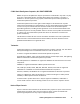
Minimum configuration of 9960 subsystem Disk Array Unit Disk Array Unit Disk Array Unit Figure 2.2 9960 Subsystem Frames Figure 2.
2.2 Components of the Controller Frame The 9900 controller frame contains the control and operational components of the subsystem. For the 9910 subsystem, the controller frame also contains the disk array components. The 9900 controller is fully redundant and has no active single point of failure. All controller frame components can be repaired or replaced without interrupting access to user data. The key features and components of the controller frame are: 2.2.1 Storage clusters (see section 2.2.
2.2.2 Nonvolatile Shared Memory The nonvolatile shared memory contains the cache directory and configuration information for the 9900 subsystem. The path group arrays (e.g., for dynamic path selection) also reside in the shared memory. The shared memory is duplexed, and each side of the duplex resides on the first two cache cards, which are in clusters 1 and 2. Even though the shared memory resides on the cache cards, the shared memory has separate power supplies and separate battery backup.
2.2.4 Multiple Data and Control Paths The 9900 subsystem uses a state-of-the-art architecture called the Hierarchical Star (HiStar) Network (HSN) which utilizes multiple point-to-point data and command paths in order to provide redundancy and improve performance. Each data and command path is independent. The individual paths between the channel or disk adapters and cache are steered by highspeed cache switch cards.
Table 2.
2.2.7 Channels The Lightning 9900™ subsystem supports all-mainframe, multiplatform, and all-open system operations and offers the following two types of host channel connections: 18 Fiber Connection (FICON™). The 9960 subsystem supports up to 16 FICON™-channel ports, and the 9910 supports up to 12 FICON™ ports. The FICON™ ports are capable of data transfer speeds of 100 MB/sec (1 Gbps). The 9900 FICON™-channel cards are available with four ports per CHIP pair.
2.2.8 Array Control Processors (ACPs) The ACPs, which control the transfer of data between the disk drives and cache, are installed in pairs for redundancy and performance. Figure 2.4 illustrates a conceptual ACP pair domain. The 9960 can be configured with up to four ACP pairs, and the 9910 has one ACP pair. All functions, paths, and disk drives controlled by one ACP pair are called an “array domain.” An array domain can contain a variety of LVI and/or LU configurations.
Table 2.
2.3 Array Frame The 9960 array frames contain the physical disk drives, including the disk array groups and the dynamic spare disk drives. Each array frame has dual AC power plugs, which should be attached to two different power sources or power panels. The 9960 can be configured with up to six array frames to provide a storage capacity of up to 88 TB. The 9910 subsystem combines the controller and disk array components in one physical frame.
Table 2.3 Disk Drive Specifications Disk Drive Type Parameter 73 GB 47 GB 18 GB 146 GB 180 GB* Formatted capacity (GB) 72.91 47.19 18.46 143.7 172.
2.3.1 Disk Array Groups The disk array group is the basic unit of storage capacity for the 9900. Each array group is attached to both ACPs of an ACP pair via eight fibre paths, which enables all disk drives in the array group to be accessed simultaneously by the ACP pair. All disk drives in an array group must have the same logical capacity. Each array frame has two canister mounts, and each canister mount can have up to 48 physical disk drives. The 9900 supports both RAID-1 and RAID-5 array groups.
Figure 2.6 illustrates RAID-5 data stripes mapped over four physical drives. Data and parity are striped across each of the disk drives in the array group (hence the term “parity group”). The logical devices (LDEVs) are evenly dispersed in the array group, so that the performance of each LDEV within the array group is the same. Figure 2.6 also shows the parity chunks that are the “Exclusive OR” (EOR) of the data chunks. The parity and data chunks rotate after each stripe.
2.4 2.4.1 Intermix Configurations RAID-1 & RAID-5 Intermix RAID technology provides full fault-tolerance capability for the disk drives of the 9900 subsystem. The 9900 supports RAID-1, RAID-5, and intermixed RAID-1 and RAID-5 configurations, including intermixed array groups within an array domain. The cache management algorithms (see section 3.3.
2.4.3 Device Emulation Intermix The 9900 subsystem supports an intermix of different device emulations (e.g., 3390-x LVIs, 3380-x LVIs, OPEN-x LUs) on the same ACP pair. Figure 2.8 illustrates an intermix of device emulation types. The only requirement is that the devices within each array group must have the same type of track geometry or format, as follows: 3390-1, -2, -3 or -9 can be intermixed within an array group. 3380-E, -J, or -K can be intermixed within an array group.
2.5 Service Processor (SVP) The Lightning 9900™ subsystem includes a built-in laptop PC called the service processor (SVP). The SVP is integrated into the controller frame and can only be used by authorized Hitachi Data Systems personnel. The SVP enables the Hitachi Data Systems representative to configure, maintain, and upgrade the 9900 subsystem. The SVP also collects performance data for all key components of the 9900 subsystem to enable diagnostic testing and analysis.
28 Chapter 2 Subsystem Architecture and Components
Chapter 3 3.1 Functional and Operational Characteristics New 9900 Features and Capabilities The Hitachi Lightning 9900™ subsystem offers the following new or improved features and capabilities which distinguish the 9900 subsystem from the 7700E subsystem: 3.2 Support for FICON™ channel interface. Sixteen (16) logical control unit (CU) images. State-of-the-art hard disk drives of 18-GB, 47-GB, 73-GB, 146-GB, and 180-GB capacities.
3.3 3.3.1 Cache Management Algorithms for Cache Control The 9900 subsystem places all read and write data in cache, and 100% of cache memory is available for read operations. The amount of fast-write data in cache is dynamically managed by the cache control algorithms to provide the optimum amount of read and write cache, depending on the workload read and write I/O characteristics.
3.4 3.4.1 Control Unit (CU) Images, LVIs, and LUs CU Images The 9900 subsystem supports the following logical CU images (emulation types): 3990-3, 3990-6E, and 2105. The 9900 subsystem is configured with one logical CU image for each 256 devices (one storage subsystem ID (SSID) for each 64 or 256 devices) to provide a maximum of sixteen CU images per subsystem. The S/390® data management features of the 9900 subsystem may have restrictions on CU image compatibility.
3.5 System Option Modes To provide greater flexibility and enable the 9900 to be tailored to unique customer operating requirements, additional operational parameters, or system option modes, are available for the 9900 subsystem. At installation, the 9900 modes are set to their default values (OFF), so make sure to discuss these settings with your Hitachi Data Systems team. The 9900 modes can only be changed by the Hitachi Data Systems representative. Table 3.2 – Table 3.
Table 3.4 System Option Modes for Open-System Connectivity Mode Level 57 Optional Description and Usage SIM notification to open-system host. ON: 9900 reports SIM to open-system host as Sense Key/Sense code. OFF: 9900 does not send SIM to open-system host. SIM will be reported as B/C300. EC=D002 will be logged in SSB.log. Set host mode 04 and System option MODE 56,57 for Sequent. Microcode level: 01-10-00-00/10 and higher. 111 Optional LUN security option.
Table 3.5 System Option Modes for ShadowImage - S/390® and ShadowImage Mode Level Description and Usage 80 Optional ShadowImage Quick Restore function. ON: 9900 does not perform the ShadowImage Quick Restore function. OFF: 9900 performs the ShadowImage Quick Restore function. 87 Optional Quick Resync by CCI (RAID Manager). ON: 9900 performs ShadowImage quick resync operation for Resync command from CCI. OFF: 9900 does not perform ShadowImage quick resync operation for Resync command from CCI.
Table 3.6 System Option Modes for TrueCopy - S/390® Synchronous & Asynchronous (continued) Mode Level 93 Optional Description and Usage TC390 Asynchronous graduated delay process for sidefile control. ON: soft delay type. OFF: strong delay type.
Table 3.7 System Option Modes for HXRC Mode Level Description and Usage 45 Optional Sleep Wait suppressing option (see modes 61, 85, 86, 97). When Mode 45 is ON and Mode 61 is ON, WRITE I/Os for LDEVs are blocked by the threshold specified by SDM. ON: Sidefile threshold does not activate Sleep Wait timer at the sleep wait threshold. OFF: Sidefile threshold activates Sleep Wait timer at the sleep wait threshold. Microcode level: -10-00-00/10 and higher.
3.6 Open Systems Features and Functions The 9900 subsystem offers many features and functions specifically for the open-systems environment. The 9900 supports multi-initiator I/O configurations in which multiple host systems are attached to the same fibre-channel interface.
3.7 Data Management Functions The 9900 subsystem provides features and functions that increase data availability and improve data management. Table 3.9 and Table 3.10 list the data management features that are currently available for the 9900 subsystem. Please refer to the appropriate user documentation for more details. Table 3.9 Data Management Functions for Open-System Users Controlled by: Remote Host Console? OS? Licensed Software? User Document(s) TrueCopy (section 3.7.
Table 3.10 Data Management Functions for S/390® Users Controlled by: Remote Host Console? OS? Licensed Software? User Document(s) Yes Yes Yes MK-91RD050 Yes Yes Yes MK-90RD012 Hitachi Extended Remote Copy (HXRC) (section 3.7.7) No Yes No Planning for IBM Remote Copy, SG242595; Advanced Copy Services, SC350355; DFSMS MVS V1 Remote Copy Guide and Reference, SC35-0169 Hitachi NanoCopy™ (section 3.7.8) N/A N/A N/A MK-90DD878, Service Offering Data Migration (section 3.7.
3.7.1 Hitachi TrueCopy (TC) Hitachi TrueCopy enables open-system users to perform synchronous and/or asynchronous remote copy operations between 9900 subsystems. The user can create, split, and resynchronize LU pairs. TrueCopy also supports a “takeover” command for remote host takeover (with the appropriate middleware support). Once established, TrueCopy operations continue unattended and provide continuous, real-time data backup.
3.7.3 Hitachi ShadowImage (SI) Hitachi ShadowImage enables open-system users to maintain subsystem-internal copies of LUs for purposes such as data backup or data duplication. The RAID-protected duplicate LUs (up to nine) are created within the same 9900 subsystem as the primary LU at hardware speeds. Once established, ShadowImage operations continue unattended to provide asynchronous internal data backup.
3.7.5 Command Control Interface (CCI) Hitachi Command Control Interface (CCI) enables users to perform Hitachi TrueCopy and Hitachi ShadowImage operations on the Lightning 9900™ subsystem by issuing commands from the UNIX®/PC server host to the 9900 subsystem. The CCI software interfaces with the system software and high-availability (HA) software on the UNIX®/PC server host as well as the TrueCopy/ShadowImage software on the 9900 subsystem.
3.7.7 Hitachi Extended Remote Copy (HXRC) The HXRC asynchronous remote copy feature of the 9900 subsystem is functionally compatible with IBM® Extended Remote Copy (XRC). HXRC provides asynchronous remote copy operations for maintaining duplicate copies of S/390® data for data backup purposes. Once established, HXRC operations continue unattended to provide continuous data backup.
3.7.8 Hitachi NanoCopy™ Hitachi NanoCopy™ is the storage industry’s first hardware-based solution which enables customers to make Point-in-Time (PiT) copies without quiescing the application or causing any disruption to end-user operations. NanoCopy™ is based on TC390 Asynchronous (TC390A), which is used to move large amounts of data over any distance with complete data integrity and minimal impact on performance.
3.7.10 Hitachi RapidXchange (HRX) Hitachi RapidXchange (HRX) enables the user to transfer data between S/390® and opensystem platforms using the ExSA™ channels or fibre channels. HRX enables high-speed data transfer without requiring network communication links or tape. Data transfer is performed via the HRX volumes, which are shared devices that appear to the S/390® host as 3390-3 or 3380-K LVIs and to the open-system host as OPEN-3 or OPEN-K LUs.
3.7.12 HARBOR® File-Level Backup/Restore Tantia™ Technologies HARBOR® File-Level Backup/Restore features an integrated architecture and includes: A host component on MVS, Integrated clients for desktops and servers, LAN-based distributed storage servers, High-speed HRX file-level backup of open-system data, and Transparent network support. Note: For further information on HARBOR® File-Level Backup/Restore, please contact your Hitachi Data Systems account team. 3.7.
3.7.15 LUN Manager LUN Manager enables users to set and define the port modes for fibre-channel ports and to set the fibre topology (e.g., FC-AL, fabric). Please connect your Hitachi Data Systems account team for further details on this feature. Note: For further information on LUN Manager, please see the Hitachi Lightning 990o™ LUN Manager User’s Guide (MK-91RD049), or contact your Hitachi Data Systems account team. 3.7.
3.7.18 FlashAccess FlashAccess allows users to store specific data in cache memory. FlashAccess increases the data access speed for the cache-resident data by enabling read and write I/Os to be performed at front-end host data transfer speeds. The FlashAccess cache areas (called cache extents) are dynamic and can be added and deleted at any time. The 9900 subsystem supports up to 1,024 addressable cache extents. FlashAccess operations can be performed for open-system LUs (e.g.
3.7.20 Hitachi SANtinel Hitachi SANtinel allows users to restrict LU accessibility to an open-systems host using the host’s World Wide Name (WWN). You can set an LU to communicate only with one or more specified WWNs, allowing you to limit access to that LU to specified open-system host(s). This feature prevents other open-systems hosts from either seeing the secured LU or accessing the data contained on it.
3.7.22 Prioritized Port and WWN Control (PPC) Prioritized Port Control (PPC) allows open-system users to designate prioritized ports (e.g., for production servers) and non-prioritized ports (e.g., for development servers) and set thresholds and upper limits for the I/O activity of these ports. PPC enables users to tune the performance of the development server without affecting the production server’s performance.
3.7.26 Hitachi CruiseControl Hitachi CruiseControl enables users to optimize their data storage and retrieval on the 9900 subsystem. Hitachi CruiseControl analyzes detailed information on the usage of 9900 subsystem resources and tunes the 9900 automatically by migrating logical volumes within the subsystem according to detailed user-specified parameters. CruiseControl tuning operations can be used to resolve bottlenecks of activity and optimize volume allocation.
3.7.27 Hitachi Graph-Track™ Hitachi Graph-Track™ (GT) allows users to monitor and collect detailed subsystem performance and usage statistics for the 9900 subsystem. GT can monitor as many as 32 subsystems on the 9900-internal LAN. GT monitors the hardware performance, cache usage, and I/O statistics of the attached subsystems and displays real-time and historical data as graphs that highlight key information such as peaks and trends.
Chapter 4 4.1 Configuring and Using the 9900 Subsystem S/390® Configuration The first step in 9900 configuration is to define the subsystem to the S/390® host(s). The three basic areas requiring definition are: Subsystem ID (SSIDs), Hardware definitions, including I/O Configuration Program (IOCP) or Hardware Configuration Definition (HCD), and Operating system definitions (HCD or OS commands).
4.2 4.2.1 S/390® Hardware Definition Hardware Definition Using IOCP (MVS, VM, or VSE) The I/O Configuration Program (IOCP) can be used to define the 9900 subsystem in MVS, VM, and VSE environments (wherever HCD cannot be used). The 9900 subsystem supports up to sixteen logical CU (LCU) images and 4096 LDEVs. Each LCU can hold up to 256 LDEV addresses. An LCU is the same as an IBM® logical sub-system (LSS). The CUADD parameter defines the CU images by number (0-F). The unit type can be 3990 or 2105.
****************************************************** **** Sample FICON CHPID / CNTLUNIT and IODEVICE ****** ****************************************************** CHPID CHPID CHPID CHPID PATH=(F9),TYPE=FC,SWITCH=07 PATH=(FB),TYPE=FC PATH=(FD),TYPE=FC PATH=(FF),TYPE=FC,SWITCH=07 CNTLUNIT CUNUMBR=8100,PATH=(F9,FB,FD,FF), LINK=(04,**,**,05), UNIT=2105,CUADD=0,UNITADD=((00,256)) CNTLUNIT CUNUMBR=8200,PATH=(F9,FB,FD,FF), LINK=(04,**,**,05), UNIT=2105,CUADD=1,UNITADD=((00,256)) CNTLUNIT CUNUMBR=8300,PATH=(F9,
Figure 4.2 shows a sample IOCP hardware definition for a 9900 configured with: 3990 ID. Two (2) LPARs called PROD and TEST sharing 4 ExSA™ (ESCON®) channels connected via 2 ESCDs to the 9980. Each switch has ports C0 and C1 attached to the 9980. Four (4) LCUs with 256 LVIs per control unit. Two (2) cu statements per logical control unit. To protect data integrity due to multiple operating systems sharing these volumes, these devices require FEATURE=SHARED.
Figure 4.3 shows a sample IOCP hardware definition for a 9900 with: 2105 ID. Eight (8) ExSA™ (ESCON®) channels directly connected to the 9900. Four (4) LCUs with 256 LVIs per control unit. One (1) cu statement per logical control unit. One hundred twenty-eight (128) 3390 base addresses per CU 0 and 1. One hundred twenty-eight (128) 3390 alias addresses per CU 0 and 1. Sixty-four (64) 3390 base addresses in CU 2. One hundred ninety-two (192) 3390 alias addresses in CU 2.
The 9960 subsystem can be configured with up to 32 connectable physical paths to provide up to 32 concurrent host data transfers. The 9910 subsystem can be configured with up to 24 connectable physical paths to provide up to 24 concurrent host data transfers. Since only 16 channel interface IDs are available (due to 16 physical channel interfaces for IBM® systems), the 9900 uses one channel interface ID for each pair of physical paths.
4.2.2 Hardware Definition Using HCD (MVS/ESA) The Hardware Configuration Definition (HCD) utility can be used to define the 9900 subsystem in an MVS/ESA environment. The HCD procedures for 3990 and 2105 controller emulation types are described below. FICON™ support requires 2105-F20 emulation. 3990 Controller Emulation. To define a 9900 subsystem with 64 or fewer LVIs, use the same procedure as for an IBM® 3990-6, 3990-6E, or 3990-3 subsystem (see Table 4.4).
2105 Controller Emulation. To define a 9900 logical control unit (LCU) and the base and alias address range that it will support, please use the following example for HCD. Note: The following HCD steps correspond to the 2105 IOCP definition shown in Figure 4.3. Note: The HCD PAV definitions must match the configurations in the 9900 subsystem. If not, error messages will occur when the HOSTs are IPL’d or the devices are varied online. 1.
14. On the Define Processor / Definition panel (see Figure 4.17), verify that the proper values are displayed, and press the return key. 15. On the Define Device to Operating System Configuration panel, input an S next to the Config ID (see Figure 4.18), and then press the return key. 16. The Define Device Parameters / Features panel displays the default device parameters (see Figure 4.19). Note: The WLMPAV parameter defaults to “YES”. Set the desired parameters, and then press return key. 17.
OS/390 Release 5 HCD Command ===> ________________________________________________________________ Hardware Configuration Select one of the following. 1_ 1. 2. 3. 4. 5. 6. 7. 8. 9.
Goto Filter Backup Query Help -------------------------------------------------------------------------Control Unit List Row 27 of 40 Command ===> ___________________________________________ Scroll ===> PAGE Select one or more control units, then press Enter. To add, use F11.
Goto Filter Backup Query Help .---------------------- Select Processor / Control Unit ----------------------. | Row 1 of 1 More: > | | Command ===> ___________________________________________ Scroll ===> PAGE | | | | Select processors to change CU/processor parameters, then press Enter. | | | | Control unit number . . : 8000 Control unit type . . . : 2105 | | | | Log. Addr. -------Channel Path ID . Link Address + ------- | | / Proc. ID Att.
Goto Filter Backup Query Help .---------------------- Select Processor / Control Unit ----------------------. | Row 1 of 1 More: > | | Command ===> ___________________________________________ Scroll ===> PAGE | | | | Select processors to change CU/processor parameters, then press Enter. | | | | Control unit number . . : 8000 Control unit type . . . : 2105 | | | | Log. Addr. -------Channel Path ID . Link Address + ------- | | / Proc. ID Att.
Goto Filter Backup Query Help -------------------------------------------------------------------------I/O Device List Command ===> ___________________________________________ Scroll ===> PAGE Select one or more devices, then press Enter. Control unit number : 8000 To add, use F11. Control unit type .
.-------------------- Device / Processor Definition --------------------. | Row 1 of 1 | | Command ===> _____________________________________ Scroll ===> PAGE | | | | Select processors to change device/processor definitions, then press | | Enter. | | | | Device number . . : 8100 Number of devices . : 128 | | Device type . . .
.-------------------- Device / Processor Definition --------------------. | Row 1 of 1 | | Command ===> _____________________________________ Scroll ===> PAGE | | | | Select processors to change device/processor definitions, then press | | Enter. | | | | Device number . . : 8000 Number of devices . : 128 | | Device type . . .
.-------------------- Define Device Parameters / Features --------------------. | Row 1 of 6 | | Command ===> ___________________________________________ Scroll ===> PAGE | | | | Specify or revise the values below. | | | | Configuration ID . : PROD | | Device number . . : 8000 Number of devices : 128 | | Device type . . . : 3390B | | | | Parameter/ | | Feature Value P Req.
4.2.3 Defining the 9900 to VM/ESA® Systems 64 or Fewer LVIs: To define a 9900 with less than or equal to 64 LVIs to a VM/ESA® system, use the same procedure as for an IBM® 3990-6, 3990-6E, or 3990-3 subsystem. To define a 9900 with more than 64 LVIs to VM/ESA®, enter the LVI address range, storage type, and sharing option for the subsystem as shown below (the address range varies for each installation).
4.3 4.3.1 S/390® Operations Initializing the LVIs The 9900 LVIs require only minimal initialization before being brought online. Figure 4.21 shows an MVS ICKDSF JCL example of a minimal init job to write a volume ID (VOLID) and volume table of contents (VTOC). Note: HPAV base and alias devices require additional definition. For further information, please refer to the Hitachi Lightning 9900™ Hitachi Parallel Access Volume (HPAV) User and Reference Guide (MK-91RD047).
Table 4.6 ICKDSF Commands for 9900 Contrasted to RAMAC Command Argument Subsystem Return Code INSPECT KEEPIT RAMAC CC = 12 Invalid parameter(s) for device type. 9900 CC = 12, F/M = 04 (EC=66BB). RAMAC CC = 4 Parameter ignored for device type. 9900 CC = 12, F/M = 04 (EC=66BB) Unable to establish primary and alternate track association for track CCHH=xxxx. RAMAC CC = 4 Parameter ignored for device type - skip. 9900 CC = 12, F/M = 04 (EC=66BB) Primary track CCHH-xxxx found unrecoverable.
4.3.3 MVS Cache Operations To display the 9900 cache statistics under MVS DFSMS, use the following operator command: D SMS, CACHE. Figure 4.22 shows the cache statistics reported by the 9900. The 9900 reports cache statistics for each SSID in the subsystem. Because the dynamic cache management algorithm has been enhanced, the read and write percentages for the 9900 are displayed as N/A.
Subsystem counter reports. The cache statistics reflect the logical caching status of the volumes. For the 9900, Hitachi Data Systems recommends that you set the nonvolatile storage (NVS) ON and the DASD fast write (DFW) ON for all logical volumes. This will not affect the way the 9900 caches data for the logical volumes.
4.3.4 VM/ESA® Cache Operations When the 9900 is managed under VM/ESA®, the following SET CACHE commands are effective across multiple SSIDs: SET CACHE SUBSYSTEM ON|OFF SET NVS SUBSYSTEM ON|OFF SET CACHEFW SUBSYSTEM ON|OFF DESTAGE SUBSYSTEM 4.3.
4.4 Open-Systems Configuration After physical installation of the 9900 subsystem has been completed, the user configures the 9900 subsystem for open-system operations with assistance as needed from the Hitachi Data Systems representative. For specific information and instructions on configuring the 9900 disk devices for open-system operations, please refer to the 9900 configuration guide for the connected platform. Table 4.7 lists the currently supported platforms and the 9900 configuration guides.
4.4.1 Configuring the Fibre-Channel Ports The LUN Manager remote console software enables users to configure the fibre-channel ports for the connected operating system and operational environment (e.g., FC-AL or fabric). If desired, Hitachi Data Systems can configure the fibre-channel ports as a fee-based service. For further information on LUN Manager, see Hitachi Freedom Storage™ Lightning 9900™ LUN Manager User’s Guide (MK-91RD049), or contact your Hitachi Data Systems account team.
4.5 4.5.1 Open Systems Operations Command Tag Queuing The 9900 supports command tag queuing for open-system devices. Command tag queuing enables hosts to issue multiple disk commands to the fibre-channel adapter without having to serialize the operations. Instead of processing and acknowledging each disk I/O sequentially as presented by the applications, the 9900 subsystem processes requests in the most efficient order to minimize head seek operations and disk rotational delay.
4.5.3 Path Failover Support The user should plan for path failover (alternate pathing) to ensure the highest data availability. In the open-system environment, alternate pathing can be achieved by host failover and/or I/O path failover software. The 9900 provides up to 32 fibre ports to accommodate alternate pathing for host attachment. Figure 4.25 shows an example of alternate pathing. The LUs can be mapped for access from multiple ports and/or multiple target IDs.
4.5.4 Remote SIM (R-SIM) Reporting The 9900 subsystem automatically reports all SIMs to the Remote Console PC (if powered on and booted). These R-SIMs contain the same information as the SIMs reported to mainframe hosts, enabling open-system users to monitor 9900 operations from the Remote Console PC. The 9900 remote console software allows the user to view the R-SIMs by date/time or by controller and to manage the R-SIM log file on the Remote Console PC. 4.5.
Chapter 5 Planning for Installation and Operation This chapter provides information for planning and preparing a site before and during installation of the Hitachi Lightning 9900™ subsystem. Please read this chapter carefully before beginning your installation planning. If you would like to use any of the Lightning 9900™ features or software products (e.g.
5.2 Electrical Specifications and Requirements for Three-Phase Subsystems The Lightning 9960 subsystem supports three-phase power. At this time the 9910 subsystem supports only single-phase power. 5.2.1 Internal Cable Diagram Figure 5.1 illustrates the internal cable layout of a three-phase 9960 subsystem.
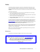
5.2.2 Power Plugs Figure 5.2 illustrates the power plugs for a three-phase 9960 disk array unit (USA). Figure 5.3 illustrates the power plugs for a three-phase 9960 disk array unit (Europe). R&S 3760 or 3760PDG Provided with DKU-F405I-3UC To be prepared as apart of power facility to power distribution board to Disk Array R&S 3754 or 3934 CB101 Front View of 9960 Disk Array Figure 5.
5.2.3 Features Table 5.1 lists the features for a three-phase 9960 subsystem. Table 5.1 5.2.4 9960 Three-Phase Features Frame Feature Number Description Comments Controller N/A — If using three-phase power, the Controller Frame receives its input power from the first disk array frame. All Controller single-phase features must be removed to allow three-phase power for the Controller.
5.2.5 Input Voltage Tolerances Table 5.3 lists the input voltage tolerances for the three-phase 9960. Transient voltage conditions must not exceed +15-18% of nominal and must return to a steady-state tolerance within of +6 to -8% of the normal related voltage in 0.5 seconds or less. Line-to-line imbalance voltage must not exceed 2.5%. Nonoperating harmonic contents must not exceed 5%. Table 5.
5.3 5.3.1 Electrical Specifications and Requirements for Single-Phase Subsystems Internal Cable Diagram Figure 5.4 and Figure 5.5 illustrate the internal cable layout of single-phase 9960 and 9910 subsystems, respectively. Max.8 To CPU •••• Disk Array Unit Disk Array Unit Disk Array Unit PCI I/F Con.
To CPU Max.8 •••• PCI I/F Con. *1 DKC Panel PC PC DKC DKU PS PS Figure 5.
5.3.2 Power Plugs Figure 5.6 through Figure 5.11 show the power plugs for the 9960 and 9910 subsystems. 3720DP Provided with DKC-F410I-1UC CB200 To be prepared as apart of power facility to 9960 Controller to power distribution board R&S3743 or 3913 Front View of 9960 Controller Figure 5.
Provided with DKC-F410I-1EC To be prepared as a part of power facility Brown to Controller CB200 L1 Hot Line L2 Hot Line G Protection Earth 200/220/230/240V AC Power Blue Green/Yellow Front View of 9960 Controller Figure 5.
R&S 3720DP Provided with DKU-F405I-1UC To be prepared as apart of power facility to power distribution board to Disk Array R&S 3743 or 3913 CB101 Front View of 9960 Disk Array Rear View of 9960 Disk Array Figure 5.
5.3.3 Features Table 5.4 lists the features for single-phase 9960 and 9910 subsystems. Table 5.
5.3.5 Input Voltage Tolerances Table 5.6 lists the input voltage tolerances for the single-phase 9900 subsystem. Transient voltage conditions must not exceed +15-18% of nominal and must return to a steady-state tolerance of between +6 and -8% of the normal related voltage in 0.5 seconds or less. Lineto-line imbalance voltage must not exceed 2.5%. Nonoperating harmonic contents must not exceed 5%. Table 5.
5.4 Dimensions and Weight Figure 5.12 and Figure 5.13 illustrate the dimensions and weight of the 9960 and 9910 DKC and DKU. Table 5.7 lists the physical specifications, Table 5.8 lists the frame and component weights, and Table 5.9 lists the subsystem weights. (Unit: mm/inches) 9960 Controller 9910 Subsystem 9960 Disk Unit 700mm/27.6” 800mm/31.5” 700mm/27.6” 580mm/27.8” 650mm/26” 800mm/31.5” 800mm/31.5” 580mm/27.8” 650mm/26” 600mm/23.6” 700mm /29.5” 750mm/29.5” Front Front Front Figure 5.
Table 5.7 9900 Physical Specifications 9960 Controller 9960 Disk Unit *6 9910 Subsystem Width 750 mm / 29.5 in *1 600 mm / 23.6 in *1 700 mm / 29.5 in *1 Depth 800 mm / 31.5 in Height 1,790 mm / 70.5 in Item Dimension (mm/in) Floor Area with no service clearance 0.6 sq meters / 6.5 sq feet 0.48 sq meters / 5.16 sq feet 0.56 sq meters / 6 sq feet Floor Area with service clearance 1.8 sq meters / 19.4 sq feet 1.44 sq meters / 15.5 sq feet 1.47 sq meters / 15.
Table 5.
5.5 5.5.1 Floor Loading and Cable Routing Requirements Service Clearance Requirements Figure 5.14 through Figure 5.17 specify the service clearance requirements (a + b) based on the floor load rating and the clearance (c). The following formula can be used to calculate floor loading to ensure that the weight of all equipment to be installed is adequately supported. Total area is defined as machine area plus half the service clearance. machine weight + (15 lb/ft2 × 0.
750 175 *2 76 Recommended value: 400 ( 300 - 570 ) *1 (Unit : mm) 175 598 *2 76 800 G 60 118 250 *2 800 2400 680 564 254 250 60 Recommended value: 300 ( 250 - 400 ) *1 *2 118 100 G 280 166 86 16 800 418 578 718 166 86 16 Front Floor cutout area for cables Screw jack Caster G Grid panel (over 450mm × 450mm) Opening on the bottom of the frame (for external cable entry) Service clearance *1: Values in parentheses show allowable range of the floor cutout dimension.
29.5" 6.9" Recommended value: 15.75" ( 11.8" - 22.4" ) *1 (Unit : inches) *2 3" 6.9" *2 3" 23.5" 31.5" G 2.4" 4.6" 9.8" Recommended value: 11.8" ( 9.8" - 15.75" ) *1 *2 31.5" 94.5" 26.8" 22.2" 10" 9.8" *2 2.4" 4.6" 3.9" G 11" 6.5" 3.4" 0.6" 31.5" 16.5" 22.75" 28.3" 6.5" 3.4" 0.6" Front Floor cutout area for cables G Screw jack Caster Grid panel (over 17.7" × 17.
600 G 150 225 70 (Unit: mm) 800 225 115 60 570 680 115 60 200 800 2400 530 150 G 300 150 70 460 70 800 Front Floor cutout area for cables Screw jack Caster Service clearance G Grid panel (perforated tile) (over 450mm × 450 mm) Figure 5.
23.6” G 8.9” 5.9” 2.8” (Unit: inches) 31.5” 8.9” 4.5” 2.4” 22.4” 26.8” 4.5” 2.4” 7.9” 31.5” 94.5” 20.9” G 5.9” 11.8” 2.8” 18.1” 5.9” 2.8” 31.5” Front Floor cutout area for cables Screw jack Caster Service clearance G Grid panel (perforated tile) (over 17.7” × 17.7”) Figure 5.
5.5.2 Minimum Subsystem Disk Configuration Figure 5.18 and Figure 5.19 illustrate the 9960 and 9910 subsystem minimum configuration. Figure 5.20 and Figure 5.21 illustrate all configurations of the 9960 and 9910 subsystems.
53.1" a *1 3.5" *3 b *1 8.8" 5.9" 15.75" (Unit: inches) 9.5" 31.5" G 2.4" 4.6" 9.8" G 2.75" 4.5" *3 2.4" 7.9" 22.4" 26.8" 31.5" 94.5" 26.8" 22.2" 11.8" 20.9" 2.4" 4.6" 9.8" *3 G 6.5" 3.4" 0.6" *2 16.5" 22.75" 28.3" d 4.5" G 11.8" 18.1" 23.6" 6.5" 3.4" 0.6" Front DKC410I 2.4" 31.5" c *1 DKU405I G Floor cutout area for cables Screw jack Caster Service clearance Grid panel (over 17.7" x 17.7") *1: Clearance (a+b) depends on the floor load rating and clearance c (see section 5.
*1 a 700 b *1 90 520 90 (Unit: mm) 800 G 59 147.5 200 682 505 400 59 2400 800 147.5 200 G 800 100 67 16 280 d *2 500 566 668 100 67 16 C *1 Front Floor cutout area for cables Screw jack Caster Service clearance 9910 Subsystem G Grid panel (over 450mm x 450mm) Figure 5.
*1 a 27.6” 3.5” 20.5” b *1 (Unit: inches) 3.5” 31.5” G 2.3” 5.8” 7.9” 31.5” 26.9” 19.9” 15.8 2.3” 5.8” 94.5” 7.9” G 31.5” 3.9” 2.6” .6” 11” 19.7” 22.3” 26.3 d *2 3.9” 2.6” .6” Front C *1 Floor cutout area for cables 9910 Subsystem Screw jack Caster Service clearance G Grid panel (over 17.7” x 17.7”) Figure 5.
5.5.3 Floor Load Rating Figure 5.22, Figure 5.23, and Table 5.10 through Table 5.13 illustrate the floor loading ratings for various 9960 and 9910 subsystem configurations. Table 5.10 Floor Load Rating for 9910 Subsystem Required Clearance (a+b) Clearance (C) in meters (feet) Floor Load Rating kg/m2 (lb/ft2) C=0 C = 0.2 (0.66) C = 0.4 (1.31) C = 0.6 (1.97) C = 1.0 (3.28) 500 (102.4) 0.6 m (2 ft) 0.3 m (1 ft) 0.1 m (.3 ft) 0 0 450 (92.2) 0.8 m (2.6 ft) 0.5 m (1.6 ft) 0.3 m (1 ft) 0.1 m (.
(Unit: mm(inches)) a *1 b *1 3150(124.0) G G G G G 800 (31.5) 800 2400 (31.5) (94.5) 16 (.6) 600 (23.6) 600 (23.6) 718 (28.3) 600 600 (23.6) (23.6) G G G G G 9960 Disk Array 800 (31.5) C *1 Front 9960 Disk Array 16 (.6) 9960 Controller 9960 Disk Array 9960 Disk Array Floor cutout area for cables Screw jack Caster Service clearance G Grid panel(Perforated tile) should be at least 450mm(17.7”) x 450mm(17.7”) Figure 5.
Table 5.12 Floor Load Rating for 9960 Controller with 4 Disk Arrays Required Clearance (a+b) Clearance (C) in meters (feet) Floor Load Rating kg/m2 (lb/ft2) C=0 C = 0.2 (0.66) C = 0.4 (1.31) C = 0.6 (1.97) C = 1.0 (3.28) 500 (102.4) 0.2 m (0.66 ft) 0 0 0 0 450 (92.2) 0.8 m (2.6 ft) 0.3 m (1 ft) 0 0 0 400 (81.9) 1.5 m (4.9 ft) 1.0 m (3.3 ft) 0.5 m (1.6 ft) 0.2 m (0.66 ft) 0 350 (71.7) 2.5 m (8.2 ft) 1.9 m (6.2 ft) 1.4 m (4.6 ft) 1.0 m (3.3 ft) 0.3 m (1 ft) 300 (61.4) 4.1 m (13.
Table 5.13 Floor Load Rating for 9960 Controller with Maximum Configuration Required clearance (a+b) 108 Clearance (C) in meters (feet) Floor Load Rating kg/m2 (lb/ft2) C=0 C = 0.2 (0.66) C = 0.4 (1.31) C = 0.6 (1.97) C = 1.0 (3.28) 500 (102.4) 0.2 m (0.66 ft) 0 0 0 0 450 (92.2) 0.9 m (3 ft) 0.3 m (1 ft) 0 0 0 400 (81.9) 1.8 m (5.9 ft) 1.1 m (3.6 ft) 0.6 m (2 ft) 0.2 m (0.66 ft) 0 350 (71.7) 3.2 m (10.5 ft) 2.4 m (7.9 ft) 1.7 m (5.6 ft) 1.1 m (3.6 ft) 0.3 m (1 ft) 300 (61.
5.5.4 Cable Requirements Table 5.14 lists the cables required for the 9960 control frame. These cables must be ordered separately, and the quantity depends on the type and number of channels and ports. ExSA™ (ESCON®), FICON™, and fibre-channel cables are available from Hitachi Data Systems. Table 5.14 Cable Requirements Cable Function PCI cable Connects 9900 to CPU power control interface. FICON™ interface cables Connects mainframe host systems, channel extenders, or FICON™ directors to 9900 ports.
5.6 Channel Specifications and Requirements Table 5.15 lists the ESCON® and FICON™ port specifications for the 9900, and Table 5.16 lists the fibre-channel port specifications for the 9900. Each 9960 subsystem supports up to four channel adapters and 32 interface ports. Each 9910 subsystem supports up to three channel adapters and 24 interface ports. Each adapter consists of two cards. Note: The 8GSE and 8HSE ports are applicable for Hitachi TrueCopy – S/390®.
5.7 5.7.1 Environmental Specifications and Requirements Temperature and Humidity Requirements Table 5.17 lists the temperature and humidity requirements for the 9900 subsystem. The recommended operational room temperature is 70–75°F (21–24°C). The recommended operational relative humidity is 50% to 55%. Table 5.
Table 5.18 9910/9960 Component Power and Heat Output Specifications Power (kVA) Heat (kW) Basic Controller frame with: - first ACP pair (2 cards total) - no cache or shared memory (2 empty cache cards) 0.95 0.89 Controller frame with: - two ACP pairs (4 cards total) - 4-GB cache, shared memory - one 8-Port ExSA™ or Fibre adapter (2 cards total) 1.3 1.
5.7.3 Loudness The acoustic emission values [loudness in dB(A)] for a maximum 9960 subsystem configuration (one DKC, six DKUs) are: Front/rear = 64 dB(A) Both sides = 57 dB(A) Note: These values were extrapolated from the values for one DKC and one DKU. 5.7.4 Air Flow Requirements The 9900 subsystem is air cooled.
5.7.5 Vibration and Shock Tolerances Table 5.21 lists the vibration and shock tolerance data for the 9900 subsystem. The 9900 can be subjected to vibration and shock up to these limits and still perform normally. The user should consider these requirements if installing the 9900 near large generators located on the floor above or below the 9900 subsystem. Generators or any other source of vibration, if not insulated or shock-mounted, can cause excessive vibration that may affect the subsystem. Table 5.
Chapter 6 6.1 Troubleshooting Troubleshooting The Hitachi Lightning 9900™ subsystem provides continuous data availability and is not expected to fail in any way that would prevent access to user data. The READY and ENABLE LEDs on the 9900 control panel must be ON when the subsystem is operating online. Table 6.1 lists potential error conditions and provides recommended actions for resolving each condition.
6.2 Service Information Messages (SIMs) The 9900 subsystem generates service information messages (SIMs) to identify normal operations (e.g., TrueCopy pair status change) as well as service requirements and errors or failures. For information on SIMs, please contact the Hitachi Data Systems Support Center (see section 6.3). (The SIM list in this document was removed because it was not complete.) SIMs can be generated by the CHIP and ACP microprocessors and by the SVP.
6.
118 Chapter 6 Troubleshooting
Appendix A Unit Conversions Table A.1 provides unit conversions for the standard (U.S.) and metric measurement systems. Table A.1 Unit Conversions for Standard (U.S.) and Metric Measures From Multiply By: To Get: British thermal units (BTU) 0.251996 Kilocalories (kcal) British thermal units (BTU) 0.000293018 Kilowatts (kW) Inches (in) 2.54000508 Centimeters (cm) Feet (ft) 0.3048006096 Meters (m) Square feet (ft2) 0.09290341 Square meters (m2) Cubic feet per minute (ft3/min) 0.
120 Appendix A Unit Conversions
Acronyms and Abbreviations ACP ASTM array control processor American Society for Testing and Materials BS BSA BTU basic (power) supply bus adapter British thermal unit °C ca CFW CH CHP CHIP CHPID CKD CL CPU CSA CSW CU CVS degrees centigrade/Celsius cache cache fast write channel channel processor or channel path client-host interface processor channel path identifier count key data cluster central processing unit Canadian Standards Association cache switch control unit custom volume size DASD dB(A) DF
122 FDR FICON™ F/M FWD Fast Dump/Restore Fiber Connection (IBM® trademark for fiber connection technology) format/message fast wide differential g Gb GB Gbps GLM GUI acceleration of gravity (9.
LVI LW logical volume image (also called device emulation) long wavelength m MB MIH mm MP MPLF MR ms, msec MVS meter megabyte missing interrupt handler millimeter microprocessor Multi-Path Locking Facility magnetoresistive millisecond Multiple Virtual Storage (including MVS/370, MVS/ESA, MVS/XA) NAS NVS network-attached storage nonvolatile storage OEM OFC ORM OS original equipment manufacturer open fibre control online read margin operating system P/DAS PC PCI PPRC PS PPRC/dynamic address switching
124 TC390 TC390A TID TPF TSO Hitachi TrueCopy – S/390® Hitachi TrueCopy – S/390® Asynchronous target ID Transaction Processing Facility Time Sharing Option (an IBM® System/370 operating system option) UCB UIM UL µm unit control block unit information module Underwriters’ Laboratories micron, micrometer VA VAC VDE VM VOLID volser XRC VSE VTOC volt-ampere volts AC Verband Deutscher Elektrotechniker Virtual Machine (an IBM® S/390® system control program) volume ID volume serial number Extended Remote Cop