H9A11 Cabinet Installation/Owner's Guide Part Number: EK-H9A11-IN.
June 1999 COMPAQ COMPUTER CORPORATION SHALL NOT BE LIABLE FOR TECHNICAL OR EDITORIAL ERRORS OR OMISSIONS CONTAINED HEREIN, NOR FOR INCIDENTAL OR CONSEQUENTIAL DAMAGES RESULTING FROM THE FURNISHING, PERFORMANCE, OR USE OF THIS MATERIAL. THIS INFORMATION IS PROVIDED “AS IS” AND COMPAQ COMPUTER CORPORATION DISCLAIMS ANY WARRANTIES, EXPRESS, IMPLIED OR STATUTORY AND EXPRESSLY DISCLAIMS THE IMPLIED WARRANTIES OF MERCHANTABILITY, FITNESS FOR PARTICULAR PURPOSE, GOOD TITLE AND AGAINST INFRINGEMENT.
Table of Contents Preface Overview .................................................................................................................................... v Intended Audience ...................................................................................................................... v How to Use This Guide ............................................................................................................... v Organization ......................................................
Figures Figure 1-1 H9A11 Cabinet ...................................................................................................... 1–2 Figure 2-1 Unpacking the Cabinet ........................................................................................... 2–4 Figure 2-2 Installing the Ramps............................................................................................... 2–6 Figure 2-3 Deskidding the Cabinet ..............................................................................
Preface Overview This guide provides the information necessary to install the H9A11 Cabinet. This guide does not provide information concerning systems that can be installed in the cabinet. For information concerning systems installed in the cabinet, refer to the respective documentation shipped with the system. Intended Audience The instructions in this guide are for Compaq Customer Service representatives and customer maintenance personnel who are familiar with computer hardware and operating systems.
Organization This guide is organized as follows: Chapter 1, Introduction -- Provides an overview of the H9A11 Cabinet features and specifications. Chapter 2, Installation -- Provides site preparation, unpacking, and installation information. Appendix A, Field Replaceable Units (FRUs) -- Provides a list of the field replaceable units (FRUs) for the H9A11 Cabinet.
Reader's Comments Compaq welcomes your comments on this or any other manual. You can send your comments to Compaq in the following ways: • Internet electronic mail: reader-comments@digital.com • Mail: Compaq Computer Corporation Information Design PKO3-2/21J 129 Parker Street Maynard, MA 01754-2199 For additional information, call 1-800-344-4825.
This is some white text.
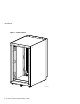
1 Introduction 1.1 Description The H9A11 Cabinet (Figure 1-1) is a low-cost, computer-equipment enclosure system that meets the Electronic Industries Association (EIA) standard 310C and the International Electrotechnical Commission (IEC) 297 standards and can accommodate fixed or slidemounted chassis that fit into a standard 48.26-cm (19-in.) rack.
Introduction Figure 1-1 H9A11 Cabinet scale=.12 scale=.
Introduction 1.2 Specifications Specifications for the H9A11 Cabinet are as follows: Physical Height, overall 110.0 cm (43.31 in.) Width, overall 60.0 cm (23.60 in.) Depth, overall 86.0 cm (33.86 in.) Maximum vertical rackmounting space 93.35 cm (36.75 in.) Maximum vertical rackmounting space (with power distribution unit installed)\ 88.9 cm (35.00 in.) Horizontal rack width Standard 48.26-cm (19-in.) Weight - Cabinet with power distribution unit 80.
Introduction Power cord (attached) 1–4 H9A11 Cabinet Installation/Owner’s Guide H7600-AA - 120 Vac with L5-30P connector H7600-AB - 240 Vac with L6-20P connector H7600-DB - 240 Vac with IEC 309 connector
2 Installation 2.1 Introduction This chapter provides the following information: • Tools Required (Section 2.2) • Site Planning (Section 2.3) • Unpacking (Section 2.4) • Installation Procedures (Section 2.5) 2.2 Tools Required The tools needed to install the H9A11 Cabinet are: • Utility knife • Phillips screwdriver • 5/8-inch box wrench or adjustable wrench 2.3 Site Planning The cabinet requires a space of 60.0 cm (23.60 in.) by 86.0 cm (33.86 in.).
Installation _______________________ WARNING __________________________ High Leakage Current --- An insulated earthing conductor that is identical in size, insulation material, and thickness to the earthed and unearthed branchcircuit supply conductors (except that it is green with or without one or more yellow stripes) is to be installed as part of the branch circuit that supplies the unit or system.
Installation 2.4 Unpacking The cabinet is shipped on a wooden pallet. Proceed as follows to unpack the cabinet: 1. 2. 3. Position the pallet with the cabinet in an area that provides sufficient workspace for unpacking. Ensure that there is sufficient clearance in front of the pallet (marked with a large F) to roll the cabinet down the ramps. Refer to Figure 2-1. Cut and remove the plastic wrapping that secures the corner posts and the carton to the cabinet. The carton contains the two ramps.
Installation Figure 2-1 Unpacking the Cabinet Not for external loads 1 J1 F 2 2 Not for external loads scale=.
Installation 6. Refer to Figure 2-2. Remove the four shipping bolts and brackets that secure the four cabinet leveler feet to the pallet . __________________________ Note _____________________________ The ramps attach to the front of the pallet. Therefore, the cabinet will have to be rolled frontwards down the ramps. ____________________________________________________________ 7. Remove the ramps ¡ from the shipping carton and set the ramps in the holes ¢ provided at the front of the pallet .
Installation Figure 2-2 Installing the Ramps 7 6 8 scale=.
Installation ________________________WARNING __________________________ In the following step, use sufficient personnel to move the cabinet off the pallet. The cabinet weighs 80.74 kg (178 lb) empty, and can weigh up to 420.94 kg (928 lb) fully configured. If equipment is installed in the cabinet, the cabinet may become top heavy and could accelerate rapidly down the ramps if not restrained. Be prepared to guide and control the motion of the cabinet.
Installation Figure 2-3 Deskidding the Cabinet Not for external loads scale=.
Installation 2.5 Installation Procedures During the installation of the cabinet, one or more of the following procedures may be needed: • Removing and Replacing the Rear Lift-Off Door (Section 2.5.1) • Removing and Replacing the Front Filler Panels (Section 2.5.2) • Pulling Out and Adjusting the Stabilizer Bar (Section 2.5.3) • Removing and Replacing the Power Distribution Unit (Section 2.5.
Installation 2.5.1 Removing and Replacing the Rear Lift-Off Door The rear lift-off door provides access into the rear of the cabinet. To remove the rear lift-off door, refer to Figure 2-4 and proceed as follows: Removal 1. Remove the two Phillips-head screws that secure the rear lift-off door to the two brackets at the top rear of the cabinet. 2. Grasp both sides of the rear lift-off door about midway up the door.
Installation Figure 2-4 Removing and Replacing the Rear Lift-Off Door 1 4 MAIN POWE R 2 3 LJ-04807 H9A11 Cabinet Installation/Owner's Guide 2–11
Installation 2.5.2 Removing and Replacing the Front Filler Pa nels To remove a front filler panel, refer to Figure 2-5 and proceed as follows: Removal Grasp the front filler panel on both sides and then pull straight back away from the cabinet. Replacement To replace a front filler panel , align the sockets on the front filler panel (refer to the exploded view) with the appropriate ball studs on the rails and push the panel into place.
Installation Figure 2-5 Removing and Replacing the Front Filler Panels scale=.12 scale=.
Installation 2.5.3 Pulling Out and Adjusting the Stabilizer Bar The stabilizer bar pulls straight out from the bottom front of the cabinet as shown in Figure 2-6. When the stabilizer bar is fully extended, adjust the foot at the end of the stabilizer bar until it touches the floor. _______________________ WARNING __________________________ The stabilizer bar must be fully extended before any system is extended out of the cabinet on its slides.
Installation Figure 2-6 Pulling Out and Adjusting the Stabilizer Bar Not for external loads Scale=.12 then .
Installation 2.5.4 Removing and Replacing the Power Distribu tion Unit _______________________ WARNING __________________________ There can be one or more PDUs per cabinet. Ensure that all systems installed in the cabinet are turned off as described in the system documentation before performing the following procedure. ___________________________________________________________ To remove a power distribution unit, refer to Figure 2-7 and proceed as follows: Removal 1.
Installation Figure 2-7 Removing and Replacing the Power Distribution Unit 2 1 Not for external loads J1 J2 J3 M AI N PO W ER J4 Ne s’appliqu pas a l’alimentation externe.
This is some white text.
A Field Replaceable Units (FRUs) Table A-1 lists the field replaceable units (FRUs) for the H9A11 cabinet.
Help