MAINTENANCE & SERVICE GUIDE Compaq Deskpro 1000 Series of Personal Computers
Notice The information in this guide is subject to change without notice. COMPAQ COMPUTER CORPORATION SHALL NOT BE LIABLE FOR TECHNICAL OR EDITORIAL ERRORS OR OMISSIONS CONTAINED HEREIN; NOR FOR INCIDENTAL OR CONSEQUENTIAL DAMAGES RESULTING FROM THE FURNISHING, PERFORMANCE, OR USE OF THIS MATERIAL. This guide contains information protected by copyright. No part of this guide may be photocopied or reproduced in any form without prior written consent from Compaq Computer Corporation.
C ONTENTS preface Symbols and Conventions .........................................................................................................vii Technician Note........................................................................................................................viii System Serial Number ..............................................................................................................viii Locating Additional Information......................................................
3.8 Miscellaneous Parts ............................................................................................................3-9 3.9 Shipping Boxes...................................................................................................................3-9 3.10 Documentation .................................................................................................................3-9 chapter 4 Removal and Replacement Preliminaries 4.1 Electrostatic Discharge Information ..............
chapter 6 Jumper Information 6.1 System Board Jumpers .......................................................................................................6-1 6.1.1 Power-On Password Jumpers (CPW) ........................................................................6-3 6.1.2 Flash EPROM Type Selection (EP)...........................................................................6-4 6.1.3 CPU External Clock (Bus) Frequency (CLK) ...........................................................6-4 6.1.
appendix B Power Cord Set Requirements General Requirements ............................................................................................................. B-1 Country-Specific Requirements .............................................................................................. B-2 appendix C Hard Drives Device 0/Device 1 Relationship......................................................................................... C-1 Cable Select ................................................
preface This Maintenance & Service Guide is a troubleshooting guide that can be used for reference when servicing the Compaq Deskpro 1000 Series of Personal Computers. Compaq Computer Corporation reserves the right to make changes to the Compaq Deskpro 1000 Series of Personal Computers without notice.
Technician Note ! WARNING: Only authorized technicians trained by Compaq should attempt to repair this equipment. All troubleshooting and repair procedures are detailed to allow only subassembly/module-level repair. Because of the complexity of the individual boards and subassemblies, no one should attempt to make repairs at the component level or to make modifications to any printed wiring board. Improper repairs can create a safety hazard.
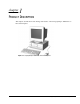
chapter 1 PRODUCT DESCRIPTION This chapter describes the model offerings and features of the Compaq Deskpro 1000 Series of Personal Computers. Figure 1-1.
1.1 Compaq Deskpro 1000 Series of Personal Computer Models The Compaq Deskpro 1000 Series of Personal Computers is available in desktop configurations described in the following sections. Table 1-1 Desktop Models Configuration Code Processor Hard Drive BWF1 P55C/166 1.6 GB BWF2 P55C/200 1.6 GB ✎ 1-2 Product Description Memory Internal Cache Graphics 16 MB 256 KB S3 Trio64V2/DX 16 MB 256 KB S3 Trio64V2/DX All models have maximum expandable memory up to 256 MB.
1.
Table 1-2 continued 1.3 Item Description Power supply 200 watt, 115 VAC, 6.0 A/230 VAC, 3.0 A Power supply fan Standard Internal piezo speaker Standard Internal battery Standard Operating System Windows 95 Two-button mouse Standard Compaq Enhanced keyboard with MS Windows-specific keys Standard System Design This section presents a design overview and functional descriptions of the key components of the Compaq Deskpro 1000 Series of Personal Computers.
1.4 Preloaded Software This computer is shipped with Windows 95 installed as the operating system. The following software is preloaded on the computer: Compaq Online Safety & Comfort Guide Microsoft Windows 95 1.5 Computer Features 1.5.1 Front Panel Controls and LEDs Figure 1-2. Front Panel Controls and LEDs 1 2 3 4 5 Diskette Drive Activity Light Turns on when the diskette drive is reading or writing. Power-On Light Turns on when the computer is turned on.
1.5.2 Drive Positions Figure1-3. Drive Positions on the Compaq Deskpro 1000 Desktop Computer 1 2 3 4 5 1-6 One 3.5-inch 1.44-MB diskette drive One 3.5-inch third-height drive bay for optional drive One 3.5-inch third-height drive bay for primary hard drive One 5.25-inch half-height drive bay for optional drive One 5.
1.5.3 Rear Panel Connectors Figure 1-4. Rear Panel Connectors 1 2 3 4 5 6 7 8 9 Voltage Select Switch (115 V U.S.
1.6 Enhanced Keyboard Figure 1-5. Enhanced Keyboard 1 Ctrl Used in combination with another key. Its effect depends on the software application you are using. 2 Windows Logo Keys Opens the Windows Start menu. Used in combination with another key. Its effect depends on the software application you are using. 3 Alt Used in combination with another key. Its effect depends on the software application you are using.
chapter 2 TROUBLESHOOTING This chapter provides troubleshooting information for the Compaq Deskpro 1000 Series of Personal Computers including: Power-On Self Test (POST)—POST messages listed in Table 2-1 include a description of the error, the probable cause, and the recommended action that should be taken to resolve the error condition. CMOS Setup Utility—Computer Setup options are available through the CMOS Setup Utility.
Table 2-1 Power-On Self-Test Messages Message Probable Cause The computer beeps: the beep consists of continuous long beeps No system memory is present. Add system memory. The computer beeps: the beep consists of one long beep followed by two short beeps A video error has occurred and the BIOS cannot initialize the video screen to display any additional information. Ensure the VGA card is installed correctly and that the monitor cable is well connected.
Table 2.1 Continued Message Probable Cause Recommended Action Hard Disk(s) Diagnosis Failure The system has run specific disk diagnostic routines. This message appears if one or more hard disks return an error when the diagnostics run. Hard disk may be damaged, and may need to be replaced. Keyboard Error or No Keyboard Present Cannot initialize the keyboard. Ensure the keyboard is attached correctly and no keys are pressed during POST.
2.2 CMOS Setup Utility The Award BIOS chip contains the ROM setup information of your computer and serves as an interface between the processor and the rest of the components on the motherboard. The CMOS Setup Utility, which is built into the BIOS and stored in the CMOS RAM, is executed when the user changes the battery or the existing settings, or when the system detects an error during POST and asks you to run the Setup utility. See Chapter 7, “Utilities,” for instructions on how to use this utility.
2.2.1 Preparing the Computer If you encounter an error condition, complete the following steps before starting problem isolation procedures: 1. Ensure proper ventilation. The computer should have a 3-inch (7.6-cm) clearance at the back of the system unit. 2. Turn off the computer and peripheral devices. CAUTION: Always ensure that the power is off before disconnecting or reconnecting the mouse, keyboard, or any other peripheral devices.
Was a nonbootable diskette loaded in the diskette drive at power-up? Are all switch settings correct? Have all jumper settings been set as instructed by the configuration utility? Was Computer Setup run after installing options (memory, disk drives, expansion boards, etc.) and before installing industry standard architecture (ISA) boards? 2.3.2 Power Problems This section identifies some quick checks for power-related problems.
2.3.3 Diskette Drive Problems This section identifies some quick checks for diskette drive–related problems. Table 2-3 Solutions for Diskette Drive Problems Problem Possible Solution Diskette drive light stays on. 1. Diskette may be damaged. In Windows 95, run SCANDISK. At the Start menu, highlight Programs, select Accessories, select System Tools, then SCANDISK. 2. Diskette could be installed incorrectly. Remove the diskette and reinsert. 3. Software program may be damaged.
2.3.4 Display Problems This section identifies some quick checks for display-related problems. Table 2-4 Solutions for Display Problems Problem Possible Solution Screen is blank. 1. Monitor is not turned on and the monitor light is not on. Turn on the monitor and check that the monitor light is on. 2. Screen save has been initiated. Press any key or move the mouse to light the screen. 3. Check the cable connection from the monitor to the computer and check the electrical outlet. 4.
2.3.5 Printer Problems This section identifies some quick checks for printer-related problems. Table 2-5 Solutions for Printer Problems Problem Possible Solution Printer will not print. 1. Printer is not turned on and online. Turn the printer on and make sure it is online. 2. The correct printer drivers for the application are not installed. Install the correct printer drivers for the application. 3. If the computer is on a network, you may not have made the connection to the printer.
2.3.6 Hard Drive Problems This section identifies some quick checks for hard drive–related problems. Table 2-6 Solutions for Hard Drive Problems Problem Possible Solution Hard drive error occurs. Hard disk has bad sectors or has failed. Use a utility to locate and block usage of bad sectors. If necessary, reformat the hard disk. Disk transaction problem. Either the directory structure is bad or there is a problem with a file. At the C:\> prompt, run SCANDISK to check for problems.
2.3.7 Hardware Installation Problems This section identifies some quick checks for hardware problems. Table 2-7 Solutions for Hardware Installation Problems Problem Possible Solutions A new device is not recognized as 1. The Computer Setup utility has not been run to configure the new part of the computer system. device. Run the Computer Setup utility. 2. When the system advised you of changes to the configuration, you did not accept them.
2.3.8 CD-ROM Drive Problems This section identifies some quick checks for CD-ROM drive problems. Table 2-8 CD-ROM Drive Problems Problem Possible Solution Cannot read compact disc. 1. CD is not properly seated in the drive. Eject the CD, correctly seat it in the drive, then reload. 2. CD has been loaded upside down. Eject the CD, turn it over, then reload. System will not boot from CD-ROM1. The CD-ROM boot is not enabled through the CMOS Setup utility. drive.
chapter 3 ILLUSTRATED PARTS CATALOG This chapter provides an illustrated parts breakdown and a reference for spare parts for the Compaq Deskpro 1000 Series of Personal Computers. Figure 3-1.
3.1 System Unit Figure 3-2. System Unit Table 3-1 System Unit Spare Parts 3-2 Description Spare Part Number Warranty Tier 1 2 3 4 System unit cover 333833-001 A Power supply, 200W (Includes fan) 333818-001 A Drive Cage 333838-001 A 333834-001 5 Base pan (chassis assembly) 6 Front bezel.
3.2 Mass Storage Devices Figure 3-3. Mass Storage Devices Table 3-2 Mass Storage Devices Description Spare Part Number Warranty Tier 1 3.5-inch, 1.44-MB, diskette drive 2 1.
3.3 Cables Figure 3-4.
3.4 Standard and Optional Boards Figure 3-5. Standard and Optional Boards Table 3-4 Standard and Optional Boards Description Spare Part Number Warranty Tier 1 System board, P55C 2 EDO SIMM, 8 MB 3 SDRAM DIMM, 16 MB 4.
3.5 Keyboards Figure 3-6. Keyboard Table 3-5 Keyboards Description Warranty Tier 1. Arabic* 333828-171 A 2. BHCSY (Bosnia-Herzegovina, Croatia, Slovenia, and Yugoslavia)* 333828-B41 A 3. Brazilian Portuguese* 333828-201 A 4. Czech* 333828-221 A 5. French* 333828-051 A 6. Hungarian* 333828-211 A 7. International 333828-B31 A 8. Korean (Hanguel)* 333828-AD1 A 9. LA Spanish* 333828-161 A 10. Russian* 333828-251 A 11. Slovakian* 333828-231 A 12.
3.6 Miscellaneous Hardware Kit Figure 3-7. Miscellaneous Hardware Kit Table 3-6 Miscellaneous Hardware Kit Description Miscellaneous hardware kit. Includes: 1 2 3 4 5 Spare Part Number 333832-001 Warranty Tier D Slot Cover (2 each) I/O Panel M3x0.
3.7 Miscellaneous Plastics Kit Figure 3-8. Miscellaneous Plastics Kit Table 3-7 Miscellaneous Plastics Kit Description Spare Part Number Warranty Tier Miscellaneous plastics kit, includes: 333831-001 D 1 2 3 4 5 6 LED Holder Card guide System board standoff (2 each) Cable twist Bezel blank, 5.
3.8 Miscellaneous Parts Figure 3-9. Miscellaneous Parts Table 3-8 Miscellaneous Parts Description Spare Part Number Warranty Tier 1 Two-button mouse 2 Battery, real-time clock (external) 3 Active heat sink (P55C/200 with thermal pad and 298792-001 A 234556-001 A 333825-001 A 333827-001 A captive clip; replaces passive heat sink) 4 Power switch (with spring, LED holder, and cable) 3.9 Shipping Boxes Table 3-9 Shipping Boxes 3.
chapter 4 REMOVAL AND REPLACEMENT PRELIMINARIES This chapter provides general service information for the computer. Adherence to the procedures and precautions described in this chapter is essential for proper service. 4.1 Electrostatic Discharge Information A sudden discharge of static electricity from your finger or other conductor can destroy staticsensitive devices or microcircuitry. Often the spark is neither felt nor heard, but damage occurs.
4.1.2 Preventing Electrostatic Damage to Equipment Many electronic components are sensitive to ESD. Circuitry design and structure determine the degree of sensitivity. The following proper packaging and grounding precautions are necessary to prevent damage to electric components and accessories. To avoid hand contact, transport products in static-safe containers such as tubes, bags, or boxes. Protect all electrostatic parts and assemblies with conductive or approved containers or packaging.
4.1.4 Grounding Workstations To prevent static damage at the workstation, use the following precautions: Cover the workstation with approved static-dissipative material. Provide a wrist strap connected to the work surface and properly grounded tools and equipment. Use static-dissipative mats, foot straps, or air ionizers to give added protection. Handle electrostatic sensitive components, parts, and assemblies by the case or PCB laminate. Handle them only at static-free workstations.
4.1.
4.2.2 Screws The screws used in the computer are not interchangeable. They may have standard or metric threads and may be of different lengths. If an incorrect screw is used during the reassembly process, it can damage the unit. Compaq strongly recommends that all screws removed during disassembly be kept with the part that was removed, then returned to their proper locations. ✎ 4.2.3 As each subassembly is removed from the computer, it should be placed away from the work area to prevent damage.
chapter 5 REMOVAL AND REPLACEMENT PROCEDURES This chapter provides subassembly/module level removal and replacement procedures for the Compaq Deskpro 1000 Series of Personal Computers. Before removing or replacing a subassembly, safeguard the CMOS settings, by writing them down, making a print screen of each CMOS setup page, or using a third-party CMOS rescue software to store the settings in a file on a write-protected diskette.
5.2 Disassembly/Assembly Sequence 5.3 Computer Feet 5.4 Preparation for Disassembly 5.5 System Unit Cover 5.6 Expansion Board 5.7 Expansion Board Guide 5.8 System Board 5.9 Graphics Memory 5.10.1 SIMM Module 5.10.2 DIMM Module 5.11 Power Supply 5.12 Microprocessor 5.13 Front Bezel 5.14 LED Retainer Assembly 5.15 5-2 LED Cables 5.16 Power Button 5.17 Bezel Blank 5.18 Battery 5.19.2 Drive Cage 5.19.3 3.5-Inch Drive 5.19.4 5.
5.3 Feet Four rubber feet are mounted to the underside of the base pan. No parts have to be removed to access the feet. The replacement feet have an adhesive surface and are shipped with a protective strip in place. Remove the feet and clean the metal with a clean, dry cloth. Remove the protective strip from the replacement feet before installation. Figure 5-2. Installing the Feet 5.4 Preparation for Disassembly 1. Remove any diskette, compact disc or tape from the computer. 2.
5.5 System Unit Cover 1. Perform preparation procedures (Section 5.4). 2. Remove the three screws on the rear of the computer to release the cover. 3. Slide the computer cover backward about 1 inch (2.5 cm). 4. Lift the cover up, then off the unit. Figure 5-3. Removing the System Unit Cover To replace the cover, reverse the previous procedure. 5.
1. Perform preparation procedures (Section 5.4). 2. Remove the system unit cover (Section 5.5). 3. Remove the screw securing the expansion board to the chassis. 4. Pull the board out of the slot. Figure 5-5. Removing a Board To replace a board, reverse the previous procedure.
5.7 Expansion Board Guide 1. Perform preparation procedures (Section 5.4). 2. Remove the system unit cover (Section 5.5). 3. Remove all expansion boards from the computer (Section 5.6). 4. Press in on the two plastic clips 1 on the right side of the guide. The guide will pop out of the chassis. Figure 5-6. Removing the Expansion Board Guide To replace the expansion board guide, reverse the previous procedure.
5.8 System Board 1. Perform preparation procedures (Section 5.4). 2. Remove the system unit cover (Section 5.5). 3. Remove all expansion boards (Section 5.6). 4. Disconnect any cables plugged into the system board. 5. Remove the seven screws securing the system board to the chassis. 6. Pinch the two standoff tabs 1 to release the system board, lifting the board at the same time to remove it from the standoffs. 7. Pull the board forward about one-half inch, then lift it up and out of the chassis.
5.9 Graphics Memory 1. Perform preparation procedures (Section 5.4). 2. Remove the system unit cover (Section 5.5). 3. Remove the video graphics board and place on a protected surface (Section 5.6). 4. Install the two 512-KB memory upgrade modules, making sure that the modules are firmly seated. ✎ Video card design varies by model. Figure 5-8. Installing a Graphics Module To replace the video graphics board, reverse the previous procedure.
5.10 Memory Modules You can expand computer memory by installing industry-standard single inline memory modules (SIMMs) or dual inline memory modules (DIMMs) on the system board. The system board includes: Four SIMM sockets that can be populated with Extended Data Output (EDO) or Fast Page Mode (FPM) modules installed in equally matched pairs; for example, two 8-MB modules, two 16-MB modules, or two 32-MB modules.
Table 5-1 Memory Configuration Options Total System Memory, MB SIMM 3 & 4 (Bank 1) 8 4&4 16 4&4 SIMM 1 & 2 (Bank 0) 8&8 4&4 16 & 16 8&8 32 & 32 8 16 16 32 16 & 16 32 & 32 128 8 16 16 & 16 64 DIMM 2 (Bank 1) 8 8&8 32 DIMM 1 (Bank 0) 32 32 64 32 & 32 64 64 64 & 64 128 128 64 & 64 256 5-10 64 & 64 Removal and Replacement Procedures
5.10.1 Installing a SIMM Module CAUTION: Static electricity can damage the electronic components or optional equipment. Before beginning these procedures, ensure that you are discharged of static electricity by briefly touching a grounded metal object. CAUTION: When handling a memory module, be careful not to touch any of the contacts. Doing so may damage the module. 1. Perform preparation procedures (Section 5.4). 2. Remove the system unit cover (Section 5.5). 3.
5.10.2 Installing a DIMM Module CAUTION: Static electricity can damage the electronic components or optional equipment. Before beginning these procedures, ensure that you are discharged of static electricity by briefly touching a grounded metal object. CAUTION: When handling a memory module, be careful not to touch any of the contacts. Doing so may damage the module. 1. Perform preparation procedures (Section 5.4). 2. Remove the system unit cover (Section 5.5). 3.
5.11 Power Supply 1. Perform preparation procedures (Section 5.4). 2. Remove the system unit cover (Section 5.5). 3. Remove the power connector cables from the system board. 4. Disconnect the power cables from the drives. 5. Remove four screws from the power supply on the rear of the chassis. 6. Remove one screw securing the power supply to the inside of the chassis. 7. Lift the power supply up until it hits the lip of the chassis. 8.
5.12 Microprocessor 5.12.1 Passive Heat Sink (P55C/166) 1. Perform preparation procedures (Section 5.4). 2. Remove the system unit cover (Section 5.5). CAUTION: When replacing a Pentium processor, you must release the heat sink retaining clip before you pull the ZIF socket handle. This clip engages the processor socket to hold the heat sink in place. ! WARNING: To reduce the risk of personal injury from hot surfaces, allow the internal system components to cool before touching. 3.
To install a processor, complete the following steps: 1. Lower the processor into the ZIF socket ensuring that pin 1 on the processor lines up with pin 1 on the ZIF socket. 2. Push the handle on the ZIF socket back into place to secure the processor. 3. Replace the heat sink and heat sink retaining clip. ✎ Ensure that the new thermal pad 3 (included in the spares kit) is in place before installing the heat sink. 4. Replace the system unit cover. 5. Plug in the computer power cord. 6.
5.12.2 Active Heat Sink (P55C/200) 1. Perform preparation procedures (Section 5.4). 2. Remove the system unit cover (Section 5.5). CAUTION: When replacing a Pentium processor, you must release the heat sink retaining clip before you pull the ZIF socket handle. This clip engages the processor socket to hold the heat sink in place. ! WARNING: To reduce the risk of personal injury from hot surfaces, allow the internal system components to cool before touching. 3.
To install a processor, complete the following steps: 1. Lower the processor into the ZIF socket ensuring that pin 1 on the processor lines up with pin 1 on the ZIF socket. 2. Push the handle on the ZIF socket back into place to secure the processor. 3. Replace the heat sink. ✎ Ensure that the new thermal pad 4 (included in the spares kit) is in place before installing the heat sink. 4. Insert the heat sink fan plug 3 into the CPU_FAN socket. 5. Replace the system unit cover. 6.
5.13 Front Bezel Assembly To remove the bezel: 1. Perform preparation procedures (Section 5.4). 2. Remove the system unit cover (Section 5.5). 3. From the inside the chassis, push the release latches 1 in and push the top of the bezel out and away from the chassis to release the bezel at those points. 4. Slide the bezel up from the bottom of the chassis to separate it from the chassis. Figure 5-14.
5.14 LED Retainer Assembly 1. Perform preparation procedures (Section 5.4). 2. Remove the system unit cover (Section 5.5). 3. Remove the front bezel assembly (Section 5.13). 4. From the outside of the chassis, press the tab 1 on either side of the LED assembly to pop it out of the chassis, then continue to slide the assembly to the left. Figure 5-15. Removing the LED Retainer Assembly and Cables To install the LED retainer assembly, reverse the previous procedure.
5.15 LED Cables 1. Perform preparation procedures (Section 5.4). 2. Remove the system unit cover (Section 5.5). 3. Remove the front bezel assembly (Section 5.13). 4. Disconnect the cables from the system board. 5. Free the cable from the cable twist attached to the floor of the chassis. Figure 5-16. Removing the LED Cables from the System Board Table 5-2 LED Cables Ref. Component Cable Color 1 2 3 Power LED Cable Green/White Hard Drive LED Cable Yellow/White Power Switch Cable Blue/White 6.
5.16 Power Button 1. Perform preparation procedures (Section 5.4). 2. Remove the system unit cover (Section 5.5). 3. Remove the front bezel (Section 5.13). 4. From the rear of the front bezel, depress the tabs on each side of the power button; the button with its spring will come out of the front of the bezel. Figure 5-17. Removing the Power Button To replace the power button, reverse the previous procedure.
5.17 Bezel Blank 1. Perform preparation procedures (Section 5.4). 2. Remove the system unit cover (Section 5.5). 3. Remove the front bezel (Section 5.13). 4. With the front bezel in an upright position, press the tabs on the side of the bezel blank towards the center of the blank and push the bezel blank out of the front of the bezel. Figure 5-18. Removing the Bezel Blank To replace the bezel blank, reverse the previous procedure.
5.18 Replacement Battery The real-time clock battery that came with the computer can be replaced with a Compaq battery or a comparable 12 microamp alkaline, 3.0 volt battery. ✎ It is important to store your CMOS settings before you install a new battery. To safeguard these settings, write them down, make a print screen of each CMOS setup page, or use a third-party CMOS rescue software to store the settings in a file on a write-protected diskette. 1. Perform preparation procedures (Section 5.4). 2.
5.19 Mass Storage Devices This section discusses the removal and replacement procedures on the Compaq Deskpro 1000 Series of Personal Computers. For information on installing an additional hard drive using cable-select technology, refer to Appendix C, “Hard Drives.” 5.19.1 Drive Positions The Compaq Deskpro 1000 Series of Personal Computers supports up to five drives, including: 1 2 3 4 5 One external 3.5-inch third-height diskette drive One internal 3.
5.19.2 Drive Cage 1. Perform preparation procedures (Section 5.4). 2. Remove the system unit cover (Section 5.5). 3. Disconnect the cables attached to the 3.5-inch hard drive and diskette drive in the drive cage. 4. Remove two screws from the top of the drive cage. 5. Slide the drive cage to the rear about one inch allowing the front of the cage to clear the bezel, then lift the cage out of the chassis. Figure 5-21. Removing the Drive Cage To replace the drive cage, reverse the previous procedure.
5.19.3 3.5-Inch Drive Before beginning the removal procedure, ensure that all removal media have been removed from the drive. CAUTION: When servicing this computer, ensure that the cables are placed in their proper locations during the reassembly process. Improper cable placement can damage the computer. 1. Perform preparation procedures (Section 5.4). 2. Remove the system unit cover (Section 5.5). 3. Remove the drive cage (Section 5.19.2). 4.
5.19.4 5.25-Inch Drive Before installing a 5.25-inch drive into a bay that has never been used, remove the metal breakaway plate covering the 5.25-inch bay. Bend the metal plate back and forth until it breaks free of the chassis. CAUTION: When servicing this computer, ensure that the cables are placed in their proper locations during the reassembly process. Improper cable placement can damage the computer. 1. Perform preparation procedures (Section 5.4). 2. Remove the system unit cover (Section 5.5). 3.
chapter 6 JUMPER INFORMATION This chapter provides information for system board jumpers and hard drives for the Compaq Deskpro 1000 Series of Personal Computers. 6.1 System Board Jumpers This section provides information for setting jumpers that enable/disable passwords and clear the configuration (CMOS). When you change a security feature, you will need to reset a jumper and reconfigure the computer to recognize this change.
Figure 6-1. Locating the Jumpers Table 6-1 System Board Jumpers 6-2 System Board ID Function Description 1 CPW Clear Password Allows you to set the password configuration to enabled or disabled. You may need to enable this jumper if you forget your password. 2 EP1, EP2 Flash EPROM Type Selection Allows you to configure the Flash EPROM chip.
6.1.1 Power-On Password Jumpers (CPW) If you forget your password, you cannot access the computer. You will need to disable the User Password feature by setting the appropriate jumper on the system board. You will then be able to access your computer. 1. Turn off the computer and any external devices. 2. Disconnect the power cord from the power outlet and any external devices from the computer. 3. Remove the computer cover. 4. Locate Jumper CPW. Figure 6-2.
6.1.2 Flash EPROM Type Selection (EP) The EP1 and EP2 jumpers allow you to configure the Flash EPROM chip: Table 6-2 EPROM Type Selection Flash EPROM EP1 Pin Pairs EP2 Pin Pairs 1M * 1-2 1-2 2M* 2-3 2-3 *Default When flashing an Intel-manufactured EPROM, move the EP jumper from pins 1-2 to 2-3. After flashing is complete, return the jumper to pins 1-2. To determine the EPROM manufacturer, locate the Award Flash EPROM chip located near the external battery.
6.1.4 CPU to SRAM Data Transacting Mode Selection (SRAM) The SRAM jumper allows you to select the CPU to SRAM data read/write mode. Table 6-4 SRAM Pin Pairs Mode Pin Pair Intel Burst (Default) for Intel Pentium CPUs, AMDK%, Cyrix, IBM* 1-2 Linear Burst 2-3 *Default setting. 6.1.
6.2 Hard Drives For more information about Compaq hard drives, refer to Appendix C in this guide. 6.2.1 1.6-GB IDE Hard Drive Jumper Settings The jumper settings for the 1.6-GB EIDE hard drive are shown below. Figure 6-3. 1.6-GB EIDE Hard Drive Jumper Settings Table 6.
chapter 7 UTILITIES 7.1 CMOS Setup Utility 7.1.1 Using the CMOS Setup Utility Execute the CMOS Setup Utility when you upgrade or repair the computer, change the battery, encounter a POST error, or choose to make a change to any of the default CMOS settings. To use the utility: 1. Turn the computer off, then on. 2. Press the Delete key when the message “Press DEL to enter Setup” appears on the screen. 3. Use the arrow keys to highlight the setup feature you want to change. 4.
Floppy mode support Bootup video display mode POST error handling selections Hard disk configurations ✎ 7.1.2.2 You can set Hard Disk Type to Auto to automatically detect the drive type. However, if you choose to not use Auto, do a screen print screen or make a note of the hard disk configuration settings for every hard drive on your computer so that you can reenter these values if CMOS becomes corrupted.
7.1.3.4 Changing a Password To change a password, complete the following steps: 1. Disable the established password by pressing Enter when prompted for the current password. 2. Establish a new password by following the instructions in “Establishing a Password” in this chapter. 7.1.3.5 Clearing a Password If you forget your password, you cannot access the computer. You will need to disable the password feature by setting the appropriate jumper on the system board.
1. Press Esc to return to the main menu. 2. Press “Save and Exit Setup” The message “SAVE to CMOS and EXIT (Y/N)?” will appear at the center of the screen. 3. Press Y [Enter] to save the changes, or 4. Press F10 (Save and Exit Setup) then press Y [Enter]. If you do not make any changes or if you want to cancel the changes you just made, see “Exit Without Saving,” in this chapter. 7.1.6 Exit Without Saving If you want to cancel the changes you made to CMOS: 1. Press Esc to return to the main menu. 2.
This automated setup is referred to as Plug and Play; there are no switches to set or manual procedures to follow; just plug it in. ✎ 7.3.1 A monitor with Asset Control is required for the Plug and Play setup to work. If you do not have a Plug and Play monitor, you can set up the display manually. Supported Resolutions Resolutions supported by the graphics controller installed on the Compaq LGX Personal Computer are presented in Chapter 8, “Specifications.” 7.3.
chapter 8 SPECIFICATIONS This chapter provides physical, environmental, and performance specifications for the computer, keyboard, and mass storage devices. 8.1 System Table 8-1 System Specifications Metric U. S. Dimensions Height Width Length 16.51 cm 42.88 cm 41.28 cm 6.5 in 16.88 in 16.25 in Weight 10.40 kg 22.
Table 8-2 System Interrupts Hardware IRQ System Function IRQ 0 Timer Interrupt (Not on ISA Bus) IRQ 1 Keyboard (Not on ISA Bus) IRQ 2 Interrupt Controller Cascade (Not on ISA Bus) IRQ 3 Serial Port (COM 2) IRQ 4 Serial Port (COM 1) IRQ 5 Enhanced Business Audio* IRQ 6 Diskette Drive IRQ 7 Parallel Port (LPT 1) IRQ 8 Real-Time Clock (Not on ISA Bus) IRQ 9 Free for PCI Use IRQ 10 Free for PCI Use IRQ 11 PCI Interrupt IRQ 12 Mouse IRQ 13 Coprocessor (Not on ISA Bus) IRQ 14 IDE In
Table 8-4 System I/O I/O Address (Hex) * System Function (Shipping Configuration) 000 - 00F 8237 DMA Controller #1 020 - 02F 8259A Master Programmable Interrupt Controller 040 - 05F Programmable Internal Timer 060 - 06F Keyboard Controller 070 - 071 System CMOS/RTC, also NMI Enable/Disable 080 Manufacture System Check Point Port 081 - 09F DMA Page Registers 0A0 - 0BF Second 8259 Programmable Interrupt Controller 0C0 - 0DF DMA Controller #2 0F0 - 0FF Numeric Data Processor 170 – 17F Se
Table 8-5 System Memory Map Size* Memory Address (Hex) System Function 64 KB FFFFFFFFh to FFFF0000h System ROM 1504 MB FDFFFFFFh to A0000000h PCI Memory Expansion 510 MB 1FF00000h to 00100000h System Memory 64 K 000FFFFFh to 000F0000h System ROM 64 KB 000EFFFFh to 000E0000h Reserved 96 KB 000DFFFFh to 000C8000h Reserved 32 KB 000C7FFFh to 000C0000h Video ROM 128 KB 000BFFFFh to 000A0000h Video RAM 640 KB 0009FFFFh to 00000000h Base Memory *All memory above the first 256 MB is n
8.2 Drives Table 8-6 Diskette Drive 1.44 MB Size and Capacity Size (cm) Size (in) High Density (MB) Low Density (KB) 8.9 3.5 1.
Table 8-7 EIDE Hard Drive 1.6-GB 8-6 Formatted Capacity Physical (MB) Logical (MB) 1624.7 1624.7 Compaq Spare Part Number 333816-001 Drive Type 65 Transfer Rate Interface (Mbytes/sec) 16.7 Typical Seek Time (including settling) Single Track (ms) Average (ms) Full Stroke (ms) 3.0 13.0 22.
8.3 Mouse Table 8-8 2-Button Mouse 8.4 Metric U.S. Dimensions Height Length Width 3.4 cm 11.3 cm 6.0 cm 1.34 in 4.45 in 2.36 in Weight 130 g 4.
8.5 Supported Graphics Resolutions Table 8-10 Supported Graphics Resolutions S3 Trio64V2/DX Graphics Card 8-8 Resolution 1-MB DRAM 2-MB DRAM 1280 × 1024 16 @ 75 Hz 256 @ 75 Hz 1024 × 768 256 @ 85 Hz 64K @ 75 Hz 800 × 600 655K @ 85 Hz 16.7M @ 75 Hz 640 × 480 655K @ 85 Hz 16.
appendix A CONNECTOR PIN ASSIGNMENTS This appendix contains the pin assignments for all external connectors: Table A-1 Keyboard Connector 6 5 4 3 KEY 1 2 Pin Signal 1 Data 2 Unused 3 Ground 4 +5 VDC 5 Clock 6 Unused Table A-2 Mouse Connector 6 5 4 3 KEY 2 1 Pin Signal 1 Data 2 Unused 3 Ground 4 +5 VDC 5 Clock 6 Unused Compaq Deskpro 1000 Series of Personal Computers A-1
Table A-3 Parallel Interface Connector 13 12 25 11 24 10 23 9 22 8 21 7 20 6 19 5 18 4 17 3 16 2 15 1 14 Pin Signal 1 Strobe# 2 Data Bit 0 3 Data Bit 1 4 Data Bit 2 5 Data Bit 3 6 Data Bit 4 7 Data Bit 5 8 Data Bit 6 9 Data Bit 7 10 Acknowledge# 11 Busy 12 Paper End 13 Select 14 Auto Linefeed# 15 Error# 16 Initialize Printer# 17 Select IN# 18-25 Signal Ground Table A-4 Serial Interface Connector 1 2 6 A-2 3 7 4 8 Connector Pin Assignments 5 9 Pin Si
Table A-5 VGA Monitor Connector 5 4 10 15 3 9 14 2 8 13 1 7 12 Pin Signal 1 Red Analog 2 Green Analog 3 Blue Analog 4 Monitor ID Bit2 5 Ground 6 Ground Analog 7 Ground Analog 8 Ground Analog 9 Not Connected 6 11 10 Ground 11 Monitor ID Bit 0 12 Bidirectional Data (SDA)* 13 Horizontal Sync 14 Vertical Sync 15 Data Clock (SCL)* *For DDC support (I2C monitors) Table A-6 USB Connector Connector 1 2 3 Pin Signal 1 VCC 2 - Data 3 + Data 4 Ground 4 Compaq De
Table A-7 IDE Drive Cable 49 1 50 2 Pin A-4 Signal Pin Signal 1 RESDRV 26 GND 2 GND 27 IOCHRDY 3 D07 28 CABLE SELECT 4 D08 29 DAK 5 D06 30 GND 6 D09 31 IRQ 7 D05 32 IO16 8 D10 33 A1 9 D04 34 PDIAG 10 D11 35 A0 11 D03 36 A2 12 D12 37 CS1FX 13 D02 38 CS3FX 14 D13 39 DASP 15 D01 40 GND 16 D14 41 AUDIO_R 17 D00 42 AUDIO_L 18 D15 43 A_GND_R 19 GND 44 A_GND_L 20 (KEY) 45 +5VMOT1 21 DREQ 46 +5VMOT2 22 GND 47 +5VMOT3 23
appendix B POWER CORD SET REQUIREMENTS The voltage select switch feature on the computer permits it to operate from any line voltage between 100-120 or 220-240 volts AC. The power cord set received with the computer meets the requirements for use in the country where you purchased the equipment. Power cord sets for use in other countries must meet the requirements of the country where you use the computer.
Country-Specific Requirements Power Cord Set Requirements—By Country Country Accredited Agency Applicable Note Numbers Australia EANSW 1 Austria OVE 1 Belgium CEBC 1 Canada CSA 2 Denmark DEMKO 1 Finland SETI 1 France UTE 1 Germany VDE 1 Italy IMQ 1 Japan MITI 3 Norway NEMKO 1 Sweden SEMKO 1 Switzerland SEV 1 United Kingdom BSI 1 United States UL 2 NOTES: 1. The flexible cord must be Type HO5VV-F, 3-conductor, 1.0 mm2 conductor size.
appendix C HARD DRIVES Compaq Computer Corporation uses IDE hard disk drives that conform to two different primary/secondary implementations. These are Conner mode and ATA-compatible mode. These two modes are incompatible with one another. Device 0/Device 1 Relationship A device 0/device 1 relationship exists when there are two hard drives connected to a single port. In this situation, one drive must be designated as the device 0, or primary, drive and the other as the device 1, or secondary, drive.
Automatic Soft-Drive Types An automatic soft-drive type is a mechanism where the system ROM and Computer Setup provide support for IDE hard drives that are not supported in the hard drive parameter table. Computer Setup automatically builds a soft-drive type when it finds that a hard drive is not in the hard drive parameter table.
Index A Alt key, 1-8 architecture, 1-3 B battery internal, 1-4 bezel illustrated, 3-2 spare part number, 3-2 BIOS features setup, 7-2 upgrading, 7-4 boxes, shipping, 3-9 C cable select description, C-1 cables, 4-5 and connectors, 4-5 illustrated, 3-4 removal and replacement, C-1 spare part numbers, 3-4 cache, 1-3 CD-ROM cable connector pin assignments, A-4 CD-ROM drive troubleshooting, 2-12 chassis illustrated, 3-2 chipset, 1-3 clearing configuration, 6-5 clearing the password, 2-5 CMOS settings restoring
troubleshooting, 2-11 hardware installation troubleshooting, 2-11 I I/O ports, 1-3 Illustrated Parts Map, viii information, locating additional, viii IntelliSafe, C-1 J jumper CLK, 6-4 CPW, 6-3 EP, 6-4 password, 6-3 SRAM, 6-5 jumper cable, C-1 jumper locations 1.62-GB IDE hard drive, 6-6 jumper settings 1.
serial interface pin assignments, A-2 serial number, 5-1 service considerations, 4-4 setup password, 7-2 changing, 7-3 clearing, 7-3 disabling, 7-2 entering, 7-2 establishing, 7-2 shipping boxes spare part numbers, 3-9 SIMM installing, 5-11 spare part number, 3-5 soft-drive type assignments, C-2 software preloaded, 1-5 required for service, 4-4 spare parts map, viii speaker internal, 1-4 SRAM CPU to SRAM data transacting mode selection, 6-5 standard and optional boards spare parts, 3-5 static shielding prot