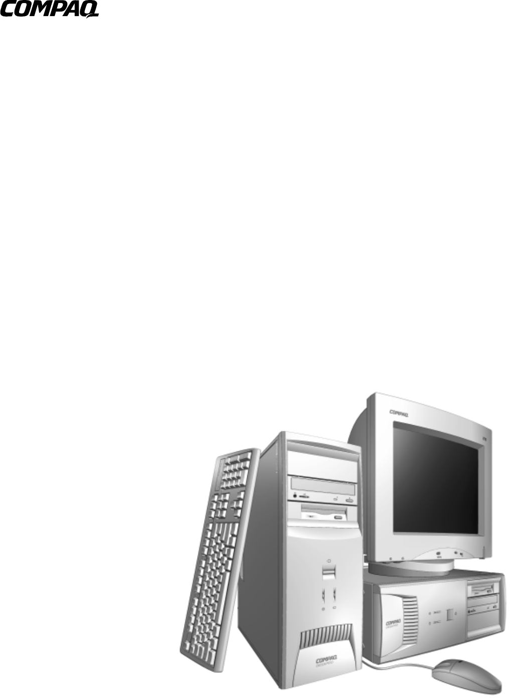
Maintenance & Service Guide Compaq Deskpro EP Series of Personal Computers
Guide to Features & Upgrades Compaq Deskpro EP Series of Personal Computers
Notice The information in this guide is subject to change without notice. COMPAQ COMPUTER CORPORATION SHALL NOT BE LIABLE FOR TECHNICAL OR EDITORIAL ERRORS OR OMISSIONS CONTAINED HEREIN; NOR FOR INCIDENTAL OR CONSEQUENTIAL DAMAGES RESULTING FROM THE FURNISHING, PERFORMANCE, OR USE OF THIS MATERIAL. This guide contains information protected by copyright. No part of this guide may be photocopied or reproduced in any form without prior written consent from Compaq Computer Corporation.
C ONTENTS preface About This Guide Symbols and Conventions ........................................................................................................ vii Technician Notes ...................................................................................................................... vii Locating Additional Documentation ....................................................................................... viii chapter 1 Product Description 1.1 Model Overview ...........................
3.2 Electrostatic Discharge Information................................................................................ 3-3 3.2.1 Generating Static ................................................................................................ 3-3 3.2.2 Preventing Electrostatic Damage to Equipment ................................................. 3-3 3.2.3 Personal Grounding Methods and Equipment.................................................... 3-4 3.2.4 Grounding Workstations...........................
chapter 5 Connectors, Jumpers, and Switches 5.1 System Board .................................................................................................................. 5-1 5.1.1 Connectors, Jumpers, and Switches.................................................................... 5-1 5.1.2 Switches.............................................................................................................. 5-4 5.1.3 Jumpers (440BX)......................................................................
preface ABOUT THIS GUIDE This Maintenance & Service Guide is a troubleshooting and repair guide that can be used for reference when servicing the Compaq Deskpro EP Series of Personal Computers. Only authorized technicians trained by Compaq should attempt to repair this equipment. Compaq Computer Corporation reserves the right to make changes to these models without notice.
Locating Additional Documentation The following documentation is available to support these products: viii ! User Documentation ! Technical Training Guides ! Compaq Service Advisories and Bulletins ! Compaq QuickFind ! Technical Reference Guide ! Compaq Service Quick Reference Guide About This Guide
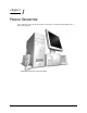
chapter 1 PRODUCT DESCRIPTION This chapter describes the model offerings and features of Compaq Deskpro EP Series of Personal Computers.
1.1 Model Overview Compaq Deskpro EP Series of Personal Computers ship as either desktop or minitower models. They contain the unique, flexible Compaq ATX chassis, which allows you to easily reconfigure the unit as a minitower by (1) removing the drives from the computer, (2) standing the unit on its side, (3) rotating the drives and bezel blanks 90 degrees, then (4) reinserting the drives into the drive bays.
1.2 System Design ! Desktop models of the Compaq Deskpro EP Series of Personal Computers use an innovative chassis to house the removable system board, expansion boards, power supply, and mass storage devices. ! Internal components are accessible when the access panel is removed. ! The front bezel is a multi-part assembly that attaches to the chassis with release latches. Attached to the back of the front bezel is a subpanel that holds the bezel blanks.
1.3 Preinstalled Software This computer ships with Windows 95, Windows 98, or Windows NT 4.0 installed as the operating system, and also contains the following preloaded software: 1.3.
1.4 Computer Features Compaq Deskpro EP Series of Personal Computers ship with a mouse and keyboard. Some models are also equipped with a CD-ROM drive. A Compaq color monitor or other compatible monitor does not ship with the computer. 1.4.1 Front Panel Controls and LEDs - 440BX Front Panel Controls and LEDs - 440BX Ref. Component/Function Ref.
1.4.2 Front Panel Controls and LEDs - Intel 810/810e Front Panel Controls and LEDs - Intel 810/ 810e Ref. Component/Function Ref. Component/Function 1 Power-On Light 6 CD-ROM Drive Busy Indicator* 2 Diskette Drive Activity Light 7 Headphone Volume Control 3 Diskette Eject Button 8 Stereo Headphone Jack 4 Serial Number 9 Dual-State Power Button 5 CD-ROM Eject Button* : Drive Activity Light** *CD-ROM models only. **Flashes when an ATAPI device, such as the hard drive, is active.
1.4.3 Rear Panel Connectors - 440BX Rear Panel Connectors - 440BX Ref.
1.4.4 Rear Panel Connectors - Intel 810/810e Rear Panel Connectors - Intel 810/810e Ref. Component Ref.
1.4.5 Drive Positions Drive Positions Reference Drive Bay Configuration 1, 2 1, 2 Two standard 5.25-inch, half-height bays for optional drives 3 3 One standard 3.5-inch, 1.44-MB diskette drive mounted with a drive adapter into a 5.25-inch bay 4, 5 4, 5 Two standard 3.5-inch drive bays; Bay 4 contains the preinstalled hard drive; Bay 5 is available for an optional hard drive ✎ Drive bay numbers are stamped on the chassis.
1.5 Serial Number Location The serial number and model information label is located on the access panel of the unit 1. A second barcode label is located on the rear of the unit 2. Serial Number Locations For the purpose of AssetControl, the serial number is embedded in CMOS and in the EEPROM on the system board and may be accessed through Diagnostics for Windows. ✎ If the system board is replaced with a spare part from Compaq, the invalid serial number condition will be recognized during POST.
chapter 2 SPARE PARTS Compaq Deskpro EP Series of Personal Computers . The Compaq Deskpro EP Series, Intel 440BX chipset models will be referred to in this MSG as 440BX. The Compaq Deskpro EP Series, Intel 810 chipset models will be referred to in this MSG as 810 or Intel 810. The Compaq Deskpro EP Series, Intel 810e chipset models will be referred to in this MSG as 810e or Intel 810e.
2.1 System Unit 2.1.
System Unit Spare Parts - 440BX Description Spare Part Number 1 Access panel 166867-001 2 Front bezel, complete with subpanel and bezel blanks 166868-001 3 Power supply, 200 Watt 166814-001 3 Power supply, 145 Watt 332863-001 4 Logo Kit, Deskpro EP (1 ea., DT and MT) 166924-001 5 Feet Miscellaneous Plastics 6 Power switch with cable, LED and switch holder (3 ea.
2.1.
System Unit Spare Parts - Intel 810/810e Description Spare Part Number 1 Access panel (includes gasket) 137384-001 2 Front bezel, complete with subpanel and bezel blanks 166868-001 3 Power supply, 200W 103748-001 * Power supply, 145W (only used with PCA 010697-101) 174871-001 4 Logo Kit, Deskpro EP (1 ea.
2.
Mass Storage Devices Description Spare Part Number 1 2.1-GB Ultra ATA hard drive (33/5400) 332861-001 * 3.2-GB Ultra ATA hard drive (33/5400) 332866-001 * 4.3-GB Ultra ATA hard drive (33/5400) 327646-001 * 4.3-GB Ultra ATA hard drive (66/5400) 134197-001 * 5.1-GB Ultra ATA hard drive (33/5400) 166872-001 * 6.4-GB Ultra ATA hard drive (33/5400) 166973-001 * 6.4-GB Ultra ATA hard drive (66/5400) 134198-001 * 10.0-GB Ultra ATA hard drive (33/5400) 320662-001 * 10.
2.
Cables Description Spare Part Number Cable Kit includes: 166879-001 1a Diskette drive cable without twist, 11” 440BX only, (166838-001) 1b Audio cable, 21”, (288489-002) * IDE hard drive cable, 7” 440BX only, (247116-001) * IDE hard drive/CD-ROM cable, 14” 440BX only, (242947-001) Cable Kit (use on Intel 800 series products) includes: 2a 166879-002 Diskette drive cable with twist, 11”, with pull tab, center polarization (143218-001) * IDE Ultra ATA hard drive/CD-ROM cable, 10”, with pull tab
2.
Standard and Optional Boards Description Spare Part Number 1a PII System board, three-DIMM model (440BX) (PCA=009635-101). 166813-001 1b PII System board, two-DIMM model (440BX) (PCA=008312-101). 332857-001 * PII/PIII System board, three-DIMM model (440BX) (PCA=010233-101) Shipped on all PII and PIII units after 2/23/99). 1c Intel 810 System Board (PCA=010174-101). * Intel 810e System Board (PCA=010546-101). 118053-001 401963-001 161422-001 * Intel 810e System Board (PCA=010697-101).
Standard and Optional Boards, continued 2-12 Spare Parts
Standard and Optional Boards Continued Description Spare Part Number * Processor, PIII, 533/133, (137365-003), w/heatsink (401405-003), 164402-001 keyed heatsink clip (120891-001), spacer (168092-001), retention mechanism (350767-005). Use on 010546-101 system board. * Processor, PIII, 550/100 (352772-006), w/heatsink (401405-001), 133840-001 and thermal compound (243199-002). Use on 010233-101 system board. Processor, PIII, 550/100 (158353-002), w/heatsink, clip, and thermal 176743-001 interface.
Standard and Optional Boards Continued Description 4 * 166871-001 166970-001 * ATI RAGE PRO GRAPHICS IIC 332865-001 * Matrox MGA G100 AGP graphics board 328011-001 * Matrox Millenium G200-SD graphics card with 8-MB memory (shipped on all PII and PIII units after 2/23/99) Matrox Millenium G200-SD graphics card with 8-MB memory 402125-001 * * Matrox Millenium G400 graphics card with 16-MB memory 167033-001 400437-001 5 33.
2.
2.6 Miscellaneous Hardware Kit Miscellaneous Hardware Kit Miscellaneous Hardware Description Spare Part Number Miscellaneous hardware kit. Includes: 166877-001 1 Cover, slot (5 ea.) (101144-001) 2a I/O Panel for 440BX (166802-002) 2b I/O Panel for Intel 810/810e (123556-001) * I/O Panel for Intel 810e – PCA=010697-101 (166808-002) 3 Fan guard (105427-003) 4 Screw, 6/32 pan head x 1/4 inch (4 ea.) (192308-001) 5 Thumbscrew (2 ea.) (440BX) (197436-001) * Thumbscrew (2 ea.
2.7 Miscellaneous Plastics Kit Miscellaneous Plastics Kit Miscellaneous Plastics Kit, Desktop and Minitower Description Spare Part Number Miscellaneous plastics kit includes: 166878-001 1 Diskette bezel (166776-001) 2 Foot, rubber (4 ea.) (166939-002) 3 Processor retainer with pins for PII processor (166889-002) (No longer included in kit) 4 Processor retainers with pins for Celeron processor (2 ea.
2.
2.9 Shipping Boxes Shipping Boxes (not illustrated) 2.10 Description Spare Part Number Return Kit with buns (U.S.
chapter 3 REMOVAL AND REPLACEMENT PRELIMINARIES 3.1 Routine Care 3.1.1 Cleaning Safety Precautions ! Never use solvents or flammable solutions to clean the computer. ! Never immerse any parts in water or cleaning solutions; apply any liquids to a clean cloth and then use the cloth on the component. ! Always turn off the computer when cleaning with liquids or damp cloths. ! Always turn off the computer before cleaning the keyboard, mouse, or air vents. ! Disconnect the keyboard before cleaning it.
3.1.3 Cleaning the Keyboard Follow all safety precautions in Section 3.1.1 before cleaning the keyboard. To clean the tops of the keys or the keyboard body, follow the procedures described in Section 3.1.2. When cleaning debris from under the keys, review all rules in Section 3.1.1 before following these procedures: CAUTION: Use safety glasses equipped with side shields before attempting to clean debris from under the keys.
3.2 Electrostatic Discharge Information A sudden discharge of static electricity from your finger or other conductor can destroy static-sensitive devices or microcircuitry. Often the spark is neither felt nor heard, but damage occurs. An electronic device exposed to electrostatic discharge (ESD) may not be affected at all and can work perfectly throughout a normal cycle. The device may function normally for a while, then degrade in the internal layers, reducing its life expectancy.
3.2.3 Personal Grounding Methods and Equipment Use the following equipment to prevent static electricity damage to equipment: ! Wrist straps are flexible straps with a minimum of one-megohm +/- 10% resistance in the ground cords. To provide proper ground, a strap must be worn snug against bare skin. The ground cord must be connected and fit snugly into the banana plug connector on the grounding mat or workstation.
! Static-dissipative table or floor mats with hard tie to ground ! Field service kits ! Static awareness labels ! Wrist straps and footwear straps providing one-megohm +/- 10% resistance ! Material handling packages ! Conductive plastic bags ! Conductive plastic tubes ! Conductive tote boxes ! Opaque shielding bags ! Transparent metallized shielding bags ! Transparent shielding tubes 3.
3.3.4 Hard Drives ! Handle hard drives as delicate precision components, avoiding all physical shock and vibration. This applies to failed drives as well as replacement spares. ! Use only the packaging provided by Compaq for shipping. ! Do not remove hard drives from the shipping package for storage. Keep hard drives in their protective packaging until they are actually mounted in the CPU. ! Avoid dropping drives from any height onto any surface. 3.3.
chapter 4 REMOVAL AND REPLACEMENT PROCEDURES This chapter provides general service information for the computer. Adherence to the procedures and precautions described in this chapter is essential for proper service. After completing all necessary removal and replacement procedures, run the Diagnostics utility to verify that all components operate properly. 4.1 Disassembly Sequence Chart Use the chart below to determine the disassembly sequence for removing components from the computer. 4.3 4.4 4.5 4.
4.2 Disassembly Preparation Before adding any internal options or performing a removal/replacement: 1. Remove any diskette, compact disc, or tape from the computer. 2. Turn off the computer and any peripheral devices that are connected to it. WARNING: Power is continuous to the system board and power supply even when the power switch is turned off. To prevent damage to the unit, disconnect the power cord from the power source or the unit before beginning disassembly procedures.
4.3 Feet Installation Eight (8) rubber feet are mounted to the chassis, as shown below. No parts have to be removed to access the feet. The replacement feet have an adhesive surface and are shipped with a protective backing in place. Remove the feet from the backing before installation. If necessary, remove the old feet and remove any adhesive residue from the chassis by rubbing with your finger or a dry cloth.
4.4 Logo Plate Grasp the open side of the logo plate (left side if a desktop, bottom if a minitower) and pull outward 2. To install a new logo plate, align the guide pins in the slots 1, then press into place. ✎ When replacing the logo plate, ensure that the alignment pins are properly placed in the front bezel before pressing the logo plate into position.
4.5 Cable Lock WARNING: To avoid injury, use care in handling the separated pieces of the cable lock bracket; metal edges may be sharp. Be sure to install the bracket so that sharp edges do not extend from the edges of the computer chassis. Depending on the model, the computer includes a cable lock provision, which consists of a three-piece security bracket. The bottom part of the bracket is attached to the computer with a screw; the top part of the bracket covers the screw and prevents its removal. 1.
Installing the Cable Lock Provision - Intel 810/810e To remove the cable lock provision, reverse the above procedure.
4.6 Access Panel 1. Prepare the computer for disassembly (Section 4.2). WARNING: Power is continuous to the system board and power supply even when the power switch is turned off. To prevent damage to the unit, disconnect the power cord from the power source or the unit before beginning disassembly procedures. 2. Lay the computer down on its large base for greater stability. 3. Remove (440BX) or loosen (Intel 810/810e) the two screws that secure the access panel to the back of the computer chassis. 4.
4.7 Front Bezel 1. Prepare the computer for disassembly (Section 4.2). WARNING: Power is continuous to the system board and power supply even when the power switch is turned off. To prevent damage to the unit, disconnect the power cord from the power source or the unit before beginning disassembly procedures. 2. Lay the computer down on its large base for greater stability. 3. Remove the access panel (Section 4.6). 4. Press the two release tabs 1 at the top of the front bezel. 5.
4.8 Power Button 1. Prepare the computer for disassembly (Section 4.2). WARNING: Power is continuous to the system board and power supply even when the power switch is turned off. To prevent damage to the unit, disconnect the power cord from the power source or the unit before beginning disassembly procedures. 2. Lay the computer down on its large base for greater stability. 3. Remove the access panel (Section 4.6). 4. Remove the front bezel (Section 4.7). 5.
4.9 Subpanel and Bezel Blanks The subpanel and bezel blanks must be removed from the front bezel if you are installing a mass storage device for the first time, or if you are converting the unit from a desktop to a minitower configuration or from a minitower to a desktop configuration. WARNING: Power is continuous to the system board and power supply even when the power switch is turned off.
4.10 Power Switch CAUTION: The power switch should not be removed from the switch holder. Doing so may damage the switch components. 1. Prepare the computer for disassembly (Section 4.2). WARNING: Power is continuous to the system board and power supply even when the power switch is turned off. To prevent damage to the unit, disconnect the power cord from the power source or the unit before beginning disassembly procedures. 2. Lay the computer down on its large base for greater stability. 3.
4.11 Mass Storage Devices The Compaq Deskpro EP Series of Personal Computers support up to five drives in various configurations. Drive Bay Locations Drive Positions Reference Drive Bay Configuration 12 1, 2 Two standard 5.25-inch, half-height bays for optional drives. 3 3 One standard 3.5-inch, 1.44-MB diskette drive mounted with a drive adapter into a 5.25-inch bay. 45 4, 5 Two standard 3.
When installing additional drives, follow these guidelines: ! For optimal performance, connect hard drives to the primary controller. Connect expansion devices, such as CD-ROM, IDE tape, and diskette drives to the secondary controller. ! You may install either a third-height or a half-height drive into a half-height bay. ! You must install guide screws to ensure that the drive lines up correctly in the drive cage.
4.11.1 Removing an Internal 3.5-Inch Hard Drive 1. Prepare the computer for disassembly (Section 4.2). WARNING: Power is continuous to the system board and power supply even when the power switch is turned off. To prevent damage to the unit, disconnect the power cord from the power source or the unit before beginning disassembly procedures. 2. Lay the computer down on its large base for greater stability. 3. Remove the access panel (Section 4.6). 4. Remove the front bezel (Section 4.7). 5.
7. While holding the drivelock in the unlocked position, remove the drive from the drive bay. Removing an Internal 3.5-Inch Hard Drive 8. Remove the four guide screws from the drive. 9. Install two guide screws on each side of the replacement drive. ✎ Metric screws (M3) have a black finish while U.S. screws have a silver finish. Replace the 3.5-inch drive by reversing the above procedure.
4.11.2 Removing an External 5.25-Inch Drive 1. Prepare the computer for disassembly (Section 4.2). WARNING: Power is continuous to the system board and power supply even when the power switch is turned off. To prevent damage to the unit, disconnect the power cord from the power source or the unit before beginning disassembly procedures. 2. Lay the computer down on its large base for greater stability. 3. Remove the access panel (Section 4.6). 4. Remove the front bezel (Section 4.7). 5.
6. While the drivelock is held in the unlatched position, remove the drive from the drivebay. 7. Remove the four guide screws from the drive 1. Removing an External 5.25-inch Drive To install a new drive: 1. Install two guide screws on each side of the replacement drive 1. 2. Ensure that the guide screws line up with the guide slots 2, then slide the drive into the drive bay until it snaps into place. 3. Connect the power and signal cables to the back of the drive. 4.
4.11.3 Removing an External 3.5-Inch Drive If you are installing a second 3.5-inch diskette drive into 5.25-inch bays #1 or 2 for the first time, you must use a special adapter bracket (spare part number 243230-002). If you are installing a 3.5-inch diskette drive into 5.25-inch bay #3, you must use a special adapter bracket (spare part number 2166923-001).
6. While the drivelock is held in the unlatched position, remove the drive from the drive bay. Removing a 3.5-inch Drive and Drive Adapter from a 5.25-inch External Drive Bay 7. Remove the bracket brace 1 from the top of the drive adapter by squeezing inward on both sides 2, then rotating the brace up and out. 8. Remove the drive bezel 3. 9. Remove the two screws that secure the drive to the left side of the drive adapter. 10.
To replace the drive, reverse the previous procedures. ✎ The primary 3.5-inch diskette drive should only be installed into bay 3. Bay 3 is the bottom bay in the minitower and the topmost bay in the desktop configuration. When replacing the drive, use the existing screws. Metric screws (M3) have a black finish while U.S. screws (#6) have a silver finish. CAUTION: When servicing the computer, ensure that cables are placed in their proper locations during the reassembly process.
4.12 Removing the Drivelocks The computer chassis contains two drivelock mechanisms. Drivelock 1 secures the external drives in the desktop configuration, drivelock 2 secures all drives in the minitower and the internal drives in the desktop configuration.
1. Prepare the computer for disassembly (Section 4.2). WARNING: Power is continuous to the system board and power supply even when the power switch is turned off. To prevent damage to the unit, disconnect the power cord from the power source or the unit before beginning disassembly procedures. 2. Lay the computer down on its large base for greater stability. 3. Remove the access panel (Section 4.6). 4. Remove the front bezel (Section 4.7). 5. Remove all of the drives from the computer (Sections 4.11.1, 4.
10. Press in on the tabs to release the vertical drivelock from the chassis, then lift it up and out of the system while at the same time rotating the drivelock slightly to clear the travel slots at the bottom of the drivelock. 11. Remove the spring from the post (see inset). Removing the Vertical Drivelock To reinstall the vertical drivelock, reverse the previous procedure. To reinstall the horizontal drivelock: 1.
4.13 Expansion Boards 4.13.
4.13.2 Intel 810 and 810e Deskpro EP Expansion Slots - Intel 810 Deskpro EP Expansion Slots - Intel 810e ✎ 1 ISA expansion slot 2 ISA/ISA shared expansion slots 3 PCI expansion slots Your 810e system board may differ from the one shown.
4.13.3 Removing an Expansion Board 1. Prepare the computer for disassembly (Section 4.2). WARNING: Power is continuous to the system board and power supply even when the power switch is turned off. To prevent damage to the unit, disconnect the power cord from the power source or the unit before beginning disassembly procedures. 2. Lay the computer down on its large base for greater stability. 3. Remove the access panel (Section 4.6). 4.
4.13.4 Installing an Expansion Board 1. Prepare the computer for disassembly (Section 4.2). WARNING: Power is continuous to the system board and power supply even when the power switch is turned off. To prevent damage to the unit, disconnect the power cord from the power source or the unit before beginning disassembly procedures. 2. Lay the computer down on its large base for greater stability. 3. Remove the access panel (Section 4.6). 4.
5. Hold the board at each end and carefully rock it back and forth while pushing downward, until the connectors fit completely and firmly into the expansion slot. Installing an Expansion Board 6. Secure the board to the chassis with the retaining screw. 7. Attach any cables that came with the board. ✎ If installing a NIC board, attach the WOL power cable to connector P9 on the system board. 8. Reassemble the computer. The computer should automatically recognize the added plug and play board.
4.14 Board Guide 1. Prepare the computer for disassembly (Section 4.2). WARNING: Power is continuous to the system board and power supply even when the power switch is turned off. To prevent damage to the unit, disconnect the power cord from the power source or the unit before beginning disassembly procedures. 2. Lay the computer down on its large base for greater stability. 3. Remove the access panel (Section 4.6). 4. Remove any full-length expansion boards (Section 4.13.3). 5.
4.15 System Memory 4.15.1 440BX The 440BX comes with at least 16 megabytes of synchronous dynamic random access memory (SDRAM) dual inline memory modules (DIMMs), upgradeable to 256 or 384 MB. The memory sockets on the system board can be populated with 16-, 32-, 64-, or 128-MB DIMMs. Self-refresh DIMMs are required on models with three DIMM sockets. For proper system operation, the DIMMs must be industry standard 168-pin, 66-MHz or faster unbuffered SDRAM DIMMs.
To install a memory module, complete the following steps: 1. Prepare the computer for disassembly (Section 4.2). WARNING: Power is continuous to the system board and power supply even when the power switch is turned off. To prevent damage to the unit, disconnect the power cord from the power source or the unit before beginning disassembly procedures. 2. Lay the computer down on its large base for greater stability. 3. Remove the access panel (Section 4.6). 4.
4.16 AGP Graphics Board (440BX) 4.16.1 AGP Graphics Board Removal (440BX) 1. Prepare the computer for disassembly (Section 4.2). WARNING: Power is continuous to the system board and power supply even when the power switch is turned off. To prevent damage to the unit, disconnect the power cord from the power source or the unit before beginning disassembly procedures. 2. Lay the computer down on its large base for greater stability. 3. Remove the access panel (Section 4.6). 4.
4.16.2 Graphics Memory Upgrade (440BX) ✎ It is not necessary to remove the graphics board to install the memory upgrade module. 1. Prepare the computer for disassembly (Section 4.2). WARNING: Power is continuous to the system board and power supply even when the power switch is turned off. To prevent damage to the unit, disconnect the power cord from the power source or the unit before beginning disassembly procedures. 2. Lay the computer down on its large base for greater stability. 3.
4.17 Processor Components 4.17.1 Processor 1. Prepare the computer for disassembly (Section 4.2). WARNING: Power is continuous to the system board and power supply even when the power switch is turned off. To prevent damage to the unit, disconnect the power cord from the power source or the unit before beginning disassembly procedures. 2. Lay the computer down on its large base for greater stability. 3. Remove the access panel (Section 4.6).
Removing the Celeron Processor from the System Board - 440BX To install a new processor, reverse this procedure. Before installing a Pentium II processor, make sure the release latches are in the locked position. This will cause the processor to make an audible sound when it is properly seated in the retaining clip. 6. For the Celeron processor on the Revised Configuration, remove the heatsink retaining clip 1 by pressing down on the clip’s extended tab until it releases from the safety catch. 7.
To install a new processor, reverse this procedure. ✎ If the heatsink has a thermal pad attached to its bottom, peel off the protective paper before installing the heatsink. If the heatsink does not have a thermal pad attached to its bottom, apply a single swipe of the thermal crayon to the processor before installing the heatsink. ✎ Replace the thermal pad when you replace the heatsink on Celeron 466/66-MHz or faster processors and Pentium III 550/100-MHz or faster processors.
4.17.2 Processor Guide Rails 1. Prepare the computer for disassembly (Section 4.2). WARNING: Power is continuous to the system board and power supply even when the power switch is turned off. To prevent damage to the unit, disconnect the power cord from the power source or the unit before beginning disassembly procedures. 2. Lay the computer down on its large base for greater stability. 3. Remove the access panel (Section 4.6). 4. Remove the processor (Section 4.17.1). 5.
7. With the Tuflok pins in their full up position, firmly pull on each leg of the processor rail to disengage it from the system board. 8. Place each of the type 2 processor rail goalposts (Compaq part number 350767-002) in position with the open end facing the processor socket and push firmly down to fully seat the free end of each Tuflok in its hole. Then push down on each push-pin to secure the goalpost. Replacing the Processor Rails ! Reinstall the system board in the computer chassis.
4.18 System Board 1. Prepare the computer for disassembly (Section 4.2). WARNING: Power is continuous to the system board and power supply even when the power switch is turned off. To prevent damage to the unit, disconnect the power cord from the power source or the unit before beginning disassembly procedures. 2. Lay the computer down on its large base for greater stability. 3. Remove the access panel (Section 4.6). 4. Remove all expansion boards (Section 4.13.3). 5.
4.19 Internal Speaker 1. Prepare the computer for disassembly (Section 4.2). WARNING: Power is continuous to the system board and power supply even when the power switch is turned off. To prevent damage to the unit, disconnect the power cord from the power source or the unit before beginning disassembly procedures. 2. Lay the computer down on its large base for greater stability. 3. Remove the access panel (Section 4.6). 4. Disconnect the speaker cable from the audio board 1. 5.
6. If an oval speaker is used on the computer, remove the four screws 2 that secure the speaker 3 to the rear of the chassis. Removing the Speaker From the Rear of the Chassis To install the new speaker, reverse the preceding steps.
4.20 Lithium Battery 1. Prepare the computer for disassembly (Section 4.2). WARNING: Power is continuous to the system board and power supply even when the power switch is turned off. To prevent damage to the unit, disconnect the power cord from the power source or the unit before beginning disassembly procedures. 2. Lay the computer down on its large base for greater stability. 3. Remove the access panel (Section 4.6). 4. Locate the battery on the system board.
Locating the Battery on the System Board - Intel 810 Locating the Battery on the System Board - Intel 810e Compaq Deskpro EP Series of Personal Computers 4-43
5. Lift the battery out of the holder. Removing the Battery 6. Slide the replacement battery into position with the positive side up. The battery holder automatically secures the battery in the proper position. 7. If you removed expansion boards, reinstall them now. 8. Replace the computer access panel. 9. Reassemble the computer. 10. Reconnect the AC power cord and turn on the computer. 11. Reset the date and time, your passwords, and any special system setups, using Compaq Computer Setup.
4.21 Fan Assembly 1. Prepare the computer for disassembly (Section 4.2). WARNING: Power is continuous to the system board and power supply even when the power switch is turned off. To prevent damage to the unit, disconnect the power cord from the power source or the unit before beginning disassembly procedures. 2. Lay the computer down on its large base for greater stability. 3. Remove the access panel (Section 4.6). 4. Disconnect the fan power cable 1 from the system board. 5.
4.22 Power Supply 1. Prepare the computer for disassembly (Section 4.2). WARNING: Power is continuous to the system board and power supply even when the power switch is turned off. To prevent damage to the unit, disconnect the power cord from the power source or the unit before beginning disassembly procedures. 2. Lay the computer down on its large base for greater stability. 3. Remove the access panel (Section 4.6). 4. Disconnect all power cables from the mass storage devices and the system board.
Removing the Power Supply - Intel 810/810e To replace the power supply, reverse the above procedure.
4.23 Converting a Desktop to a Minitower 1. Prepare the computer for disassembly (Section 4.2). WARNING: Power is continuous to the system board and power supply even when the power switch is turned off. To prevent damage to the unit, disconnect the power cord from the power source or the unit before beginning disassembly procedures. 2. Lay the computer down on its large base for greater stability. 3. Remove the access panel (Section 4.6). 4. Remove the front bezel (Section 4.7). 5.
6. Rotate the drives 90 degrees, then reinstall them into the drive bays. ✎ The diskette drive should always be placed in bay number 3, the bay nearest the internal 3.5-inch drives, for proper placement within the chassis. Installing a Drive in the Minitower Configuration CAUTION: The use of unnecessary force may result in damage to the drives.
7. Reconnect the power, signal, and audio cables to the drives. 8. Remove the subpanel and rotate the bezel blanks 90 degrees (Section 4.9). CAUTION: Hold the subpanel straight when you pull it away from the front bezel. Pulling the subpanel away at an angle could damage the pins that align it within the front bezel. Changing from a Desktop 1 to a Minitower 2 Configuration 9. Replace the subpanel, front bezel, and the computer access panel. 10. Reassemble the computer.
4.24 Converting a Minitower to a Desktop 1. Prepare the computer for disassembly (Section 4.2). WARNING: Power is continuous to the system board and power supply even when the power switch is turned off. To prevent damage to the unit, disconnect the power cord from the power source or the unit before beginning disassembly procedures. 2. Lay the computer down on its large base for greater stability. 3. Remove the access panel (Section 4.6). 4. Remove the front bezel (Section 4.7). 5.
7. Rotate the drives 90 degrees, then reinstall them into the drive bays. ✎ The diskette drive should always be placed in the bay nearest the top of the chassis in the desktop configuration for proper drive clearance and access. Installing a Drive in the Desktop Configuration CAUTION: The use of unnecessary force may result in damage to the drives.
8. Reconnect the power, signal, and audio cables to the drives. 9. Remove the subpanel and rotate the bezel blanks 90 degrees (Section 4.9). CAUTION: Hold the subpanel straight when you pull it away from the front bezel. Pulling the subpanel away at an angle could damage the pins that align it within the front bezel. Converting a Minitower 2 to a Desktop 1 10. Replace the subpanel, front bezel, and the computer access panel. Reassemble the computer.
chapter 5 CONNECTORS, JUMPERS, AND SWITCHES 5.1 System Board 5.1.
System Board Overview - 440BX (Two-DIMM Board) Connectors, Jumpers, and Switches - 440BX (Two-DIMM Board) Item Description CR114 AUX LED Item Description J40 AGP Video Graphics Slot E50 CMOS Header P1 Power Supply Connector J1 DIMM 1 Expansion Slot P5 Power Switch and LED Connector J2 DIMM 2 Expansion Slot P8 Chassis Fan Connector J10 ISA Expansion Slot P9 Wake on LAN Header J11 ISA Expansion Slot P10 Diskette Drive Connector J12 PCI/ISA Dual Expansion Slot (combo) P20 IDE Con
System Board Overview - Intel 810 (Two-DIMM Board) System Board Overview - Intel 810e (Two-DIMM Board) Connectors, Jumpers, and Switches - Intel 810/810e (Two-DIMM Board) Item Item Description CR114 AUX LED Description P1 Power Supply Connector E49 Clear Password P5 Power Switch and LED Connector XMM1 DIMM 1 Expansion Slot P6 Chassis Fan XMM2 DIMM 2 Expansion Slot P7 CD-In Header J10 ISA Dual Expansion Slot 1 (combo) P8 Chassis Fan Connector J11 ISA Expansion Slot 2 P9 Wake on LA
5.1.
5.1.3 Jumpers (440BX) This section provides information on enabling/disabling passwords and clearing the configuration (CMOS). E50 Jumper Location When you change a security feature, you must reset the appropriate jumper on the system board, then reconfigure the computer to recognize this change. If the system configuration is incorrect, your computer may not work properly and you may receive error messages.
Disabling or Clearing the Power-On and Setup Passwords (440BX) ) 1. Turn off the computer and any external devices, and disconnect the power cord from the power outlet. 2. Set SW1, position 1, to the ON position. 3. Turn on the computer and allow the operating system to start. This clears the current passwords and disables the password features. 4. To re-enable the password features, turn off the computer and set SW1, position 1, to the OFF position. 5. Turn on the computer and establish new passwords.
5.1.4 Jumpers (Intel 810/810e) E49 Jumper Location When you change a security feature, you must reset the appropriate jumper on the system board, then reconfigure the computer to recognize this change. If the system configuration is incorrect, your computer may not work properly and you may receive error messages. Setting system board jumpers is part of the reconfiguration process, along with running the Computer Setup utility.
Disabling or Clearing the Power-On and Setup Passwords (Intel 810/810e) 1. Turn off the computer and any external devices, and disconnect the power cord from the power outlet. 2. Disconnect the keyboard, monitor, and any other external devices connected to the computer. 3. Remove the computer cover or access panel. 4. Locate the header and jumper labeled E49. 5. Remove the jumper from pins 1 and 2. Place the jumper over pin 2 only, in order to avoid losing it. 6. Replace the computer cover or access panel.
Clearing Configuration Memory (CMOS) - Intel 810/810e) CMOS Button (SW50) Location 1. Turn off the computer and any external devices, and disconnect the power cord from the power outlet. 2. Disconnect the keyboard, monitor, and any other external equipment connected to the computer. WARNING: To reduce the risk of personal injury from electrical shock and/or hot surfaces, be sure to disconnect the power cord from the wall outlet, and allow the internal system components to cool before touching.
5.2 Hard Drives The computer supports up to five drives in various configurations. When installing additional drives, follow these guidelines: 5.2.1 ! For optimal performance, connect hard drives to the primary controller. Connect expansion devices, such as CD-ROM, IDE tape, and diskette drives to the secondary controller. ! You may install either a third-height or a half-height drive into a half-height bay.
5.2.2 Drive Jumper Settings If you are installing a drive with a signal cable that does not support cable select, you must manually set the drive jumpers. Jumper settings for a number of different drives are shown in the tables that follow. The illustrations show the approximate location of the drive jumpers, based on the manufacturer of the drive. The actual location may vary slightly from drive to drive.
Maxtor Ultra ATA Hard Drive Jumper Settings Maxtor Ultra ATA Hard Drive Jumper Settings Definition J50 Single J Primary (in a dual drive system) J Secondary O J48 J46 J44 J42 Cable Select disabled* O enabled J 4092 Cylinder Limitation disabled* O enabled J Factory Reserved Factory Reserved J=jumper O=no jumper *=default setting 5-12 Connectors, Jumpers, and Switches O O
chapter 6 SPECIFICATIONS 6.1 Specifications 6.1.1 System Desktop Dimensions Height Width Depth 6.60 in 17.65 in 17.11 in 16.76 cm 44.83 cm 43.46 cm Minitower Dimensions Height Width Length 17.65 in 6.60 in 17.11 in 44.83 cm 16.76 cm 43.46 cm Weight (approximate, depending on configuration) 26 lb 12 kg 90-132 VAC 110-120 VAC 47-63 Hz 4.0 A 380 BTU/Hr 760 BTU/Hr 180-264 VAC 200-240 VAC 47-63 Hz 2.0 A 1.60 kg-cal/min 3.19 kg-cal/min 90-132 VAC 110-120 VAC 47-63 Hz 5.
System Specifications, continued Power, Supply, 200 Watt (Intel 810/810e) Operating Voltage Range Rated Voltage Range Rated Line Frequency Rated input current (maximum) Heat dissipation, nominal Heat dissipation, maximum 90-132 VAC 100-127 VAC 47-63 Hz 6A 525 BTU/Hr 1050 BTU/Hr 180-264 VAC 200-240 VAC 47-63 Hz 3A 2.21 kg-cal/min 4.
6.1.3 6.1.
I/O Continued I/O Address (Hex) 6-4 System Function (Shipping Configuration) 0FA Unused 0FB 483/PGL Configuration Unlock 0FC - 0FF Unused 100 - 12F Unused 130 - 131 Unused 132 - 16F Unused 170 - 177 Reserved 15C - 15D Super I/O Index/Data Register 178 - 1EF Unused 1F0 - 1F7 Fixed Disk Controller 1F8 - 1FF Unused 200 Unused 201 Unused 202 - 21F Unused 220 - 22F Audio (Alternate = 240 - 24F, 260 - 26F, or 280 - 28F) 230 - 277 Unused 278 - 27F Reserved Parallel Port 280 - 2
6.1.5 Memory Map Size Memory Address System Function 256 KB * FFFC0000h to FFFFFFFFh System ROM 3839 MB * 10000000h to FFFBFFFFh PCI Memory Expansion 255 MB * 00100000h to 0FFFFFFFh HOST or PCI Memory Expansion 128KB 000E0000h to 000FFFFFh System ROM 96 KB 000C8000h to 000DFFFFh ISA/PCI option ROMs 32 KB 000C0000h to 000C7FFFh Video ROM 128 KB 000A0000h to 000BFFFFh Video RAM 640 KB 00000000h to 0009FFFFh Base Memory All memory above the first 256 MB is non-cacheable.
6.2.2 Ultra ATA Hard Drives 3.2-GB 4.3-GB 4.3-GB 6.4-GB 6.4-GB Compaq Spare Part Number 332866-001 327646-001 134197-001 166973-001 134198-001 Drive Type 65 65 65 65 65 Revolutions Per Minute (RPM) 5400 5400 5400 5400 5400 Transfer Rate Interface (MBytes/sec) 33.3 33.3 66.6 33.3 66.6 Typical Seek Time (including settling) <1.0 Single Track (ms) <9.5 Average (ms) 20.0 Full Stroke (ms) 1.3 9.9 19.7 1.3 9.0 20.0 <1.0 <9.7 18.0 1.3 9.0 20.
6.2.
CD-ROM continued 40X Max 6-8 Applicable Disc CD-ROM mode 1, mode 2 Mixed mode (audio and data combined) CD-DA CDi ready CD-XA ready Photo CD (single and multisession) Compaq Spare Part Number 400807-001 Disc Diameter 12 cm, 8 cm Capacity 540 MB (Mode 1, 12 cm) 650 MB (Mode 2, 12 cm) 180 MB (8 cm) Center Hole Diameter 15 mm Disc Thickness 1.2 mm Track Pitch 1.6 µm Laser Beam Divergence Output Power Type Wave Length 53.5 degrees +/- 1.5 degrees 0.
6.3 Compaq Enhanced Keyboard Dimensions Height Width Depth 1.3 in 18.3 in 6.35 in 3.3 cm 46.5 cm 16.1 cm 3.0 lb 1.4 kg Dimensions Height Length Width 1.34 in 4.45 in 2.36 in 3.4 cm 11.3 cm 6.0 cm Weight 4.
6.5.2 6.5.3 6.5.4 6-10 ATI RAGE PRO IIC AGP Resolution Refresh Rate Colors Supported 2-MB EDO RAM 1600 x 1200 75 Hz 256 1280 x 1024 85 Hz 256 1152 x 864 85 Hz 65K 1024 x 768 85 Hz 65K 800 x 600 85 Hz 16.7M 640 x 480 85 Hz 16.
6.5.5 6.5.6 6.5.7 Matrox Millenium G200-SD AGP Resolution Refresh Rate Colors Supported 8-MB SDRAM 1920 x 1200 76 Hz 65K 1920 x 1200 65 Hz 16.7M 1920 x 1080 80 Hz 65K 1920 x 1080 70 Hz 16.7M 1800 x 1440 70 Hz 65K 1800 x 1440 60 Hz 16.7M 1600 x 1200 85 Hz 65K 1600 x 1200 75 Hz 16.7M 1280 x 1024 85 Hz 16.7M 1152 x 864 85 Hz 16.7M 1024 x 768 85 Hz 16.7M 800 x 600 85 Hz 16.7M 640 x 480 85 Hz 16.
6.6 6-12 Audio Controllers 440BX 440BX ESS 1869 ISA 16-bit full duplex audio with Compaq Premier!Sound Creative Labs SoundBlaster 128V PCI with Compaq Premier!Sound. Sampling rate 4 kHz to 48 kHz (adjustable) 48 kHz Full Scale Input Voltage (rms) Microphone-In Line-Input 0.050 1.0 0.1 2.0 Full Scale Output Voltage (rms) Line Output 1.0 2.
Intel 810/810e Integrated AC 97 audio with Compaq Premier!Sound Sampling rate 7 kHz to 48 kHz (adjustable) Full Scale Input Voltage (rms) Microphone-In Line-Input 0.100 2.15 Full Scale Output Voltage (rms) Line Output 1.
chapter 7 SERVICE NOTES CAUTION: Use safety glasses equipped with side shields before attempting to clean debris from under the keys. 1. As of January 1, 1999, all 300-MHz and faster Celeron and Pentium processors are shipped with the processor speeds preset. This preset processor speed will override any switch settings on the system board. 2. Compaq Deskpro EP CTO units are shipped with Compaq PC Diagnostics 10.27D preinstalled. This version fails to recognize the 22.
Index A access panel spare part number (440BX), 2-3 spare part number (Intel 810/810e), 2-5 audio controller, specifications 440BX, 6-12 Intel 810, 6-13 B battery proper disposal, 4-44 Battery locating on system board, 4-42 bezels spare part number, 2-3, 2-5 boxes, shipping, 2-19 C cable select feature, 4-13, 5-10, 5-11 cables, 3-5 service considerations, 3-5 spare part numbers, 2-9 CD-ROM spare part number, 2-7 specifications, 6-7 chassis/basepan spare part number (440BX), 2-3 spare part number (Intel 81
H hard drive jumper settings, 5-10 proper handling, 3-6 spare part number, 2-7 models, 1-2 monitor cleaning, 3-2 mouse cleaning, 3-2 spare part number, 2-18 specifications, 6-9 I O I/O specifications, 6-3 INSPECT utility, 1-9, 4-12 interrupts specifications, 6-2 J jumper location 440BX, 2-DIMM board, 5-2 440BX, 3-DIMM board, 5-1 E49 (Intel 810/810e), 5-7 E50 (440BX), 5-5 Intel 810/810e, 2-DIMM board, 5-3 K keyboard spare part numbers, 2-15 specifications, 6-9 L logo operating system ordering device d
system design, 1-3 specifications, 6-1 system board spare part number, 2-11 System memory 440BX, 4-30 810/810e, 4-30 system unit spare part numbers, 2-3, 2-5 T tools service considerations, 3-5 U Ultra ATA devices, 4-13 Ultra ATA hard drive specifications, 6-6 W Western Digital EIDE hard drive jumper settings, 5-11 Index I-3
181099-001 134011-004