Maintenance & Service Guide Compaq Evo W8000 Workstation
b Maintenance & Service Guide Compaq Evo Workstation W8000 Document Part Number: 229690-001 Spare Part Number: 229781-001 May 2001
© 2001 Compaq Computer Corporation Compaq and the Compaq logo Registered in U. S. Patent and Trademark Office. Evo is a trademark of Compaq Information Technologies Group, L. P. in the United States and other countries. Microsoft, Windows, Windows NT are trademarks of Microsoft Corporation in the United States and other countries. Intel and Pentium are trademarks of Intel Corporation in the United States and other countries.
Contents Contents Preface ABOUT THIS GUIDE . . . . . . . . . . . . . . . . . . . . . . . . . . . . . . . . . . . . . . . . . . . . . . . . . 1–vi Symbols and Conventions . . . . . . . . . . . . . . . . . . . . . . . . . . . . . . . . . . . . . . . . . . . 1–vi Technician Notes . . . . . . . . . . . . . . . . . . . . . . . . . . . . . . . . . . . . . . . . . . . . . . . . . . 1–vii Locating Additional Information . . . . . . . . . . . . . . . . . . . . . . . . . . . . . . . . . . . . . .
Contents 4.6 4.7 4.8 4.9 Battery. . . . . . . . . . . . . . . . . . . . . . . . . . . . . . . . . . . . . . . . . . . . . . . . . . . . . . . . . . . 4–6 Hood Sensor . . . . . . . . . . . . . . . . . . . . . . . . . . . . . . . . . . . . . . . . . . . . . . . . . . . . . . 4–7 Shipping Bracket. . . . . . . . . . . . . . . . . . . . . . . . . . . . . . . . . . . . . . . . . . . . . . . . . . . 4–8 Memory Components . . . . . . . . . . . . . . . . . . . . . . . . . . . . . . . . . . . . . . . . . . . . . .
Contents 5.2 Mass Storage. . . . . . . . . . . . . . . . . . . . . . . . . . . . . . . . . . . . . . . . . . . . . . . . . . . . . . 5.2.1 Hard Drives . . . . . . . . . . . . . . . . . . . . . . . . . . . . . . . . . . . . . . . . . . . . . . . . . 5.2.2 CD-ROM or DVD-ROM Drive. . . . . . . . . . . . . . . . . . . . . . . . . . . . . . . . . . 5.2.3 Zip Drive . . . . . . . . . . . . . . . . . . . . . . . . . . . . . . . . . . . . . . . . . . . . . . . . . . .
Contents vi Maintenance & Service Guide
Preface ABOUT THIS GUIDE This Maintenance & Service Guide is a troubleshooting and repair guide that can be used for reference when servicing the Compaq Evo W8000 Workstation. Only authorized technicians trained by Compaq should attempt to repair this equipment. Compaq Computer Corporation reserves the right to make changes to the these models without notice.
Preface Technician Notes Å WARNING: Only authorized technicians trained by Compaq should attempt to repair this equipment. All troubleshooting and repair procedures are detailed to allow only subassembly/module level repair. Because of the complexity of the individual boards and subassemblies, no one should attempt to make repairs at the component level or to make modifications to any printed wiring board. Improper repairs can create a safety hazard.
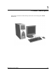
1 Product Description This chapter describes the model offerings and features of the Compaq Evo W8000 Workstation.
Product Description 1.1 Product Features The W8000 ships with a mouse and keyboard. Some models are also equipped with a CD-ROM, DVD-ROM, or CDRW drive. A Compaq color monitor or other compatible monitor does not ship with the workstation. 1.1.1 Front Panel Controls and LEDs Ref. 1–2 Component/Function Ref.
Product Description 1.1.2 Rear Panel Connectors Ref. Component/Function Ref.
Product Description 1.1.3 Drive Positions The workstation provides seven drive bays. Bays 1 through 3 are located in the 3.5-inch removable hard drive cage, which is located behind the side access panel of the workstation. Drive bays 4 through 7 are located on the front of the workstation. The drives support various drive configurations. Item Component Description 1 Bay 1 Part of the removable hard drive cage. A 3.5-inch, third-height bay that supports a 1.0-inch hard drive or a 1.6-inch hard drive.
Product Description 1.2 Serial Number Location Provide the workstation serial number to Compaq whenever you request information or order spare parts. There are two serial number locations on the unit. One is located on the top front corner of the access panel. The other is on the rear of the unit below the power supply. For asset control, the serial number is also embedded in the Electrically Erasable Programmable Read Only Memory (EEPROM) on the system board.
Product Description 1–6 Maintenance & Service Guide
2 Spare Parts Spare parts are listed and illustrated on the Illustrated Parts Map, spare part number 229782-001.
Spare Parts 2–2 Maintenance & Service Guide
3 Removal & Replacement Preliminaries This chapter provides general service information for the workstation. Adherence to the procedures and precautions described in this chapter is essential for proper service. Ä 3.1 CAUTION: When the workstation is plugged into an AC power source there is always voltage applied to the system board. You must disconnect the power cord from the power source before opening the workstation to prevent system board or component damage.
Removal & Replacement Preliminaries 3.1.1 Generating Static The following table shows that: ■ Different activities generate different amounts of static electricity. ■ Static electricity increases as humidity decreases.
Removal & Replacement Preliminaries 3.1.3 Personal Grounding Methods and Equipment Use the following equipment to prevent static electricity damage to equipment: ■ Wrist straps are flexible straps with a maximum of one-megohm +/- 10% resistance in the ground cords. To provide proper ground, a strap must be worn snug against bare skin. The ground cord must be connected and fit snugly into the banana plug connector on the grounding mat or workstation.
Removal & Replacement Preliminaries 3.1.
Removal & Replacement Preliminaries 3.2 Routine Care 3.2.1 General Cleaning Safety Precautions 1. Never use solvents or flammable solutions to clean the workstation. 2. Never immerse any parts in water or cleaning solutions; apply any liquids to a clean cloth and then use the cloth on the component. 3. Always unplug the workstation when cleaning with liquids or damp cloths. 4. Always unplug the workstation before cleaning the keyboard, mouse, or air vents. 5. Disconnect the keyboard before cleaning it.
Removal & Replacement Preliminaries Ä CAUTION: Never remove a wide leveled key (like the space bar) from the keyboard. If these keys are improperly removed or installed, the keyboard may not function properly. ■ Cleaning under a key may be done with a swab moistened with isopropyl alcohol and squeezed out. Be careful not to wipe away lubricants necessary for proper key functions. Use tweezers to remove any fibers or dirt in confined areas. Allow the parts to air dry before reassembly. 3.2.
Removal & Replacement Preliminaries 3.3.2 Tools and Software Requirements To service the workstation, you need the following: ■ Torx T-15 screwdriver (Compaq screwdriver with bits, PN 161946-001) ■ Phillips screwdriver (may sometimes be used in place of the Torx screwdriver) ■ Diagnostics software ■ Compaq tamper-resistant T-15 wrench (Smart Cover FailSafe Key, PN 166527-001) or Compaq tamper-resistant bits (Smart Cover FailSafe Key, PN 166527-002) 3.3.
Removal & Replacement Preliminaries ■ Before handling a drive, ensure that you are discharged of static electricity. While handling a drive, avoid touching the connector. For more information about preventing electrostatic damage, refer to Section 3.1, “Electrostatic Discharge.” ■ Do not use excessive force when inserting a drive. ■ Avoid exposing a hard drive to liquids, temperature extremes, or products that have magnetic fields such as monitors or speakers. 3.3.
4 Removal & Replacement Procedures This chapter provides general service information for the workstation. Adherence to the procedures and precautions described in this chapter is essential for proper service. After completing all necessary removal and replacement procedures, run the Diagnostics utility to verify that all components operate properly. 4.1 Disassembly Sequence Chart Use the chart below to determine the disassembly sequence for removing components from the workstation. 4.3 4.4 4.
Removal & Replacement Procedures 4.2 Preparation for Disassembly See Chapter 3, “Removal and Replacement Preliminaries,” for initial procedures. 1. Close any open software applications. 2. Exit the operating system. 3. Remove any diskette or compact disc from the workstation. 4. Turn off the workstation and any peripheral devices that are connected to it. Ä CAUTION: Turn off the workstation before disconnecting any cables. 5.
Removal & Replacement Procedures 4.3 Cable Lock The workstation comes standard with a cable lock provision for attaching a padlock and/or cable lock. If installed, the locks must be removed before accessing internal components. 1. Unlock and remove the cable lock or the padlock. 2. Remove the security bracket (plate) seated over the cable lock bracket. 3. Unfasten the retaining screw to release the cable lock bracket.
Removal & Replacement Procedures 4.4 Workstation Feet Four (4) rubber feet are mounted to the chassis, as shown below. No parts have to be removed to access the feet. The replacement feet have an adhesive surface and are shipped with a protective backing in place. Remove the backing from the feet before installation. If necessary, remove the old feet and remove any adhesive residue from the chassis. To replace the feet, reverse the above procedure.
Removal & Replacement Procedures 4.5 Ä Access Panel CAUTION: Do not operate the workstation with the access panel removed. The panel is an integral part of the cooling system; removing it while the system is running may adversely affect data integrity and the life of your system. 1. Prepare the workstation for disassembly (Section 4.2), then place it on its side.
Removal & Replacement Procedures 4.6 Battery 1. Prepare the workstation for disassembly (Section 4.2), then place it on its side. Å WARNING: Power is continuous to the system board and power supply even when the power switch is turned off. To prevent damage to the unit, disconnect the power cord from the power source or the unit before beginning disassembly procedures. 2. Remove the access panel (Section 4.5). 3. Locate the battery on the system board.
Removal & Replacement Procedures 4.7 Hood Sensor 1. Prepare the workstation for disassembly (Section 4.2), then place it on its side. Ä CAUTION: Before removing the access panel, ensure that the workstation is turned off, and all cables are disconnected from the back of the workstation. 2. Remove the access panel (Section 4.5). 3. Unplug the cable from the system board 1. 4. Slide the sensor toward the front side of the workstation 2. 5. Remove the sensor from the chassis 3.
Removal & Replacement Procedures 4.8 Shipping Bracket 1. Prepare the workstation for disassembly (Section 4.2), then place it on its side. Ä CAUTION: Before removing the access panel, ensure that the workstation is turned off, and all cables are disconnected from the back of the workstation. 2. Remove the access panel (Section 4.5). 3. Remove the four screws that connect shipping bracket to the front of the chassis. 4. Remove the shipping bracket from the chassis.
Removal & Replacement Procedures 4.9 Memory Components The W8000 includes a memory expansion board that must be removed from the system board to remove and replace memory modules. 4.9.1 Overview The W8000 has two Direct Rambus memory channels and uses Error Checking and Correcting (ECC) Direct Rambus Inline Memory Modules (RIMMS). Continuity RIMMs (CRIMMs) are also available to populate empty RIMM slots. Dual Direct Rambus memory channels operate on the following three principles: 1.
Removal & Replacement Procedures 4.9.2 Removing the Memory Expansion Board 1. Prepare the workstation for disassembly (Section 4.2), then place it on its side. 2. Remove the access panel (Section 4.5). 3. Locate the memory expansion board that is connected to the system board. 4. Remove the torx screw on the back of the metal slot cover that secures the memory board to the expansion board slot. 5.
Removal & Replacement Procedures 4.9.3 RIMM Installation Guidelines Å WARNING: To reduce the risk of personal injury when replacing or removing RIMMs, allow the module being removed from the RIMM slot sufficient time to cool. RIMM temperatures can reach 100°C (212°F). Ä CAUTION: When handling a RIMM, be careful not to touch any of the contacts. Doing so may damage the module. Ä CAUTION: Static electricity can damage the electronic components of the workstation or optional boards.
Removal & Replacement Procedures 4.9.4 RIMM Slot Locations The W8000 ships with an eight-RIMM socket memory expansion board (two RIMM sockets per memory channel). Identifier RIMM Socket Memory Channel 1 RIMM Socket 1 Channel B-Top 2 RIMM Socket 2 Channel A-Top 3 RIMM Socket 3 Channel B-Top 4 RIMM Socket 4 Channel A-Top 5 RIMM Socket 5 Channel B-Bottom 6 RIMM Socket 6 Channel A-Bottom 7 RIMM Socket 7 Channel B-Bottom 8 RIMM Socket 8 Channel A-Bottom 4.9.
Removal & Replacement Procedures 4.9.6 Installing a Memory Device Å WARNING: To reduce the risk of personal injury when replacing or removing RIMMs, allow the module being removed from the RIMM slot sufficient time to cool. RIMM temperatures can reach 100°C (212°F). Ä CAUTION: When handling a RIMM, be careful not to touch any of the contacts. Doing so may damage the module. Ä CAUTION: Static electricity can damage the electronic components of the workstation or optional boards.
Removal & Replacement Procedures 4.10 Front Bezel 1. Prepare the workstation for disassembly (Section 4.2), then place it on its side. Ä CAUTION: Before removing the access panel, ensure that the workstation is turned off, and all cables are disconnected from the back of the workstation. 2. Remove the access panel (Section 4.5). 3. Press the two front bezel release latches 1 and remove the front bezel 2. To replace the front bezel, reverse the above procedure.
Removal & Replacement Procedures 4.11 Blank Drive Bezel 1. Prepare the workstation for disassembly (Section 4.2), then place it on its side. Ä CAUTION: Before removing the access panel, ensure that the workstation is turned off, and all cables are disconnected from the back of the workstation. 2. Remove the access panel (Section 4.5). 3. Remove the front bezel (Section 4.10). 4. Pinch together the retainer snaps on the back of the front bezel 1.
Removal & Replacement Procedures 4.12 Front I/O Board and Power Switch Assembly 1. Prepare the workstation for disassembly (Section 4.2), then place it on its side. 2. Remove the access panel (Section 4.5). 3. Remove the front bezel (Section 4.10). 4. Disconnect the cable from the system board 1. 5. Remove the four screws connecting the cage to the chassis 2, then remove the cage from the chassis 3. 6. Disconnect the cable from the I/O board mounted in the cage 4. 7.
Removal & Replacement Procedures 4.13 EMI/Cooling Shield An EMI/cooling shield covers bays 5 and 6 to provide proper cooling and EMI protection. 1. Prepare the workstation for disassembly (Section 4.2), then place it on its side. Ä CAUTION: Before removing the access panel, ensure that the workstation is turned off, and all cables are disconnected from the back of the workstation. 2. Remove the access panel (Section 4.5). 3. Remove the front bezel (Section 4.10). 4.
Removal & Replacement Procedures 4.14 Mass Storage Devices 4.14.1 Drive Positions The W8000 can house up to seven mass storage devices. The following illustration identifies the physical drive locations. Refer to the corresponding table for a list of the recommended drive configurations. Item Component Description 1 Bay 1 Part of the removable hard drive cage. A 3.5-inch, third-height bay that supports a 1.0-inch hard drive or a 1.6-inch hard drive. 2 Bay 2 Part of the removable hard drive cable.
Removal & Replacement Procedures 4.14.2 Spare Screws A total of 17 extra spare screws are provided on the side of the air plenum. The top group of eight screws are standard 6-32 x 3/16-inch long screws and are for installing hard drives in the removable hard drive cage. The bottom group of nine screws are metric M-3 x 5 mm long and are for installing removable media storage devices in the front drive bays.
Removal & Replacement Procedures 4.14.3 Removing a Hard Drive from Bays 5 or 6 Drive bays 5 and 6 can be configured with either a 1.0-inch or 1.6-inch hard drive. To remove a hard drive: ✎ Before removing a SCSI device, please read the “SCSI Devices” appendix. 1. Prepare the workstation for disassembly (Section 4.2), then place it on its side. 2. Remove the access panel (Section 4.5). 3. Remove the front bezel (Section 4.10). 4. Remove the EMI/Cooling shield (Section 4.13). 5.
Removal & Replacement Procedures 4.14.4 CD-ROM Drive ✎ This procedure also applies to removing other similar devices. 1. Prepare the workstation for disassembly (Section 4.2), then place it on its side. 2. Remove the access panel (Section 4.5). 3. Remove the front bezel (Section 4.10). 4. Remove the two screws securing the right side of the drive. 5. Slide the drive slightly out of the drive cage. 6. Disconnect all cables from the rear of the drive. 7. Pull the drive straight out of the chassis.
Removal & Replacement Procedures 4.14.5 Diskette Drive Important: Before beginning the removal procedure, be sure there is no diskette in the drive. 1. Prepare the workstation for disassembly (Section 4.2), then place it on its side. Ä CAUTION: Before removing the access panel, ensure that the workstation is turned off, and all cables are disconnected from the back of the workstation. 2. Remove the access panel (Section 4.5). 3. Remove the front bezel (Section 4.10). 4.
Removal & Replacement Procedures 4.15 Expansion Boards W8000 supports 1.5V (typically 4X) AGP and AGP Pro cards only. Older ✎ The type AGP cards (3.3V) are not supported and will NOT fit in the AGP socket. This workstation contains one AGP and six PCI sockets. The following illustration identifies the physical location of these sockets. Item Component 1 One 1.
Removal & Replacement Procedures 4.15.1 Removing an Expansion Board 1. Prepare the workstation for disassembly (Section 4.2), then place it on its side. Ä CAUTION: Before removing the access panel, ensure that the workstation is turned off, and all cables are disconnected from the back of the workstation. 2. Remove the access panel (Section 4.5). 3. Disconnect any cables attached to the expansion board. 4. Remove the expansion board retaining screw. 5.
Removal & Replacement Procedures 4.15.2 Installing an Expansion Board 1. Prepare the workstation for disassembly (Section 4.2). 2. Remove the access panel (Section 4.5) and locate the correct vacant PCI slot. 3. Remove the screw securing the expansion slot cover, then remove the slot cover 4. Slide the expansion board into the expansion slot and press the board firmly into place.
Removal & Replacement Procedures 4.16 Air Baffles 4.16.1 Main Baffle 1. Prepare the workstation for disassembly (Section 4.2), then place it on its side. Ä CAUTION: Before removing the access panel, ensure that the workstation is turned off, and all cables are disconnected from the back of the workstation. 2. Remove the access panel (Section 4.5). on workstation options, you may have to unplug SCSI and/or IDE ✎ Depending cables from the system board.
Removal & Replacement Procedures 4.16.2 Power Supply Air Baffle 1. Prepare the workstation for disassembly (Section 4.2), then place it on its side. Ä CAUTION: before removing the access panel, ensure that the workstation is turned off, and all cables are disconnected from the back of the workstation. 2. Remove the access panel (Section 4.5). 3. Remove the clear, main baffle from the chassis (Section 4.16.1). 4. Remove the power supply air baffle from the hook and loop adhesive tabs.
Removal & Replacement Procedures 4.17 Power Supply Å WARNING: Only qualified personnel should perform this procedure. Do not reconnect power to the workstation until the workstation cover is replaced. Connecting the power before replacing the workstation cover can result in personal injury or equipment damage. Å■ WARNING: To reduce the risk of electric shock or damage to the equipment: Do not disable the power cord grounding plug. The ground plug is an important safety feature.
Removal & Replacement Procedures 4.18 Removable Hard Drive Cage 4.18.1 Removing the Removable Hard Drive Cage Drive bays 1 through 3 are located in the removable hard drive cage. 1. Prepare the workstation for disassembly (Section 4.2), then place it on its side. 2. Remove the access panel (Section 4.5). 3. Loosen the power supply air baffle, as necessary (Section 4.16.2). 4. Remove/loosen the screws 1 on top of the cage. removable hard drive cage may be retained by either torx screws or ✎ The thumbscrews.
Removal & Replacement Procedures 4.18.2 Removing a Hard Drive from the Removable Hard Drive Cage (Bays 1-3) removable hard drive cage supports up to three 1.0-inch hard drives or two ✎ The 1.6-inch hard drives. Other than using different screw holes, the removal and replacement for both drives is the same. 1. Prepare the workstation for disassembly (Section 4.2), then place it on its side. 2. Remove the access panel (Section 4.5). 3. Disconnect the cables from the back of the hard drive. 4.
Removal & Replacement Procedures 4.18.3 Installing a Hard Drive in the Removable Hard Drive Cage (Bays 1-3) The removable hard drive cage can be configured with up to three 1.0-inch hard drives or two 1.6-inch hard drives. Other than using different screw holes, the installation for both types of drives is the same. ✎ Before installing a SCSI device, please read the “SCSI Devices” appendix. ✎ If only one SCSI hard drive is used, install it in bay 2. 1. Prepare the workstation for disassembly (Section 4.
Removal & Replacement Procedures 5. Install the drive into the drive cage using four screws. See the following illustration for screw locations. Item Location 1 1.0-inch drive 2 1.6-inch drive 3 1.0-inch drive 4 1.0-inch or 1.6-inch drive 6. Reinstall the removable hard drive cage. 7. Connect the SCSI signal cables and power cables to the back of the drive(s). 8. Reassemble the workstation.
Removal & Replacement Procedures 4.19 Heatsink and Processor 4.19.1 Separating the Heatsink-Processor Assembly The following sequential events must take place in order to remove the existing heatsink and processor assembly: 1. Heat the heatsink-processor assembly to an optimum temperature to break the compound bonding them together. See the following sections: ❏ “Heatsink Cool-Down Time” ❏ “Heatsink Warm-Up Time” 2. Separate the heatsink from the processor. 3.
Removal & Replacement Procedures 4.19.2 Removing the Heatsink and Processor Å WARNING: To reduce the risk of personal injury from hot surfaces, allow the internal system components to cool before touching them. Ä CAUTION: Lifting the heatsink straight up while it is in a cold state can result in damage to the processor, because it may pull the processor out of the processor socket.
Removal & Replacement Procedures 10. Open the processor socket by pulling up on the processor retention lever 1. 11. Lift the processor out of the processor socket 2. To replace the processor, reverse the above procedure. installing a new heatsink, be sure to remove the tear-away tab covering the ✎ Ifthermal material on the heatsink.
Removal & Replacement Procedures 4.19.3 Installing an Additional Processor manual Hardware Abstraction Layer (HAL) upgrade is necessary when ✎ Ainstalling a second processor after the system has gone through the software bundling process. If a second processor is installed prior to unbundling, a manual upgrade is not necessary. Hardware Abstraction Layer To update Windows NT 4.0 or Windows 2000 to recognize a second processor using the Hardware Abstraction Layer (HAL), complete the following steps: 1.
Removal & Replacement Procedures 6. Install the second processor: ❏ Ä Open the processor socket by pulling up on the processor retention lever 1. CAUTION: Processor pins are delicate and bend easily. Use extreme care when placing the processor in the socket. ❏ Insert the new processor 2 and close the retention lever. Ensure that the processor is locked into place and is not loose in the socket.
Removal & Replacement Procedures 7. Install the Voltage Regulator Module (VRM): ❏ Ä Make sure the VRM is fully inserted and properly seated. CAUTION: You must install a Compaq approved VRM when installing a second processor. Using a VRM that is incompatible with the primary VRM may severely, permanently damage the system board. ❏ Install the VRM clip, making sure the clip snaps into place. 8. Reinstall the main air baffle. Ä CAUTION: The air baffle is essential to proper cooling of the processors.
Removal & Replacement Procedures 4.20 System Board The system board has nine LEDs to help troubleshoot component-related problems. See Section 5.1.2 for more information. 1. Prepare the workstation for disassembly (Section 4.2), then place it on its side. Ä CAUTION: Before removing the access panel, ensure that the workstation is turned off, and all cables are disconnected from the back of the workstation. 2. Remove the access panel (Section 4.5). 3. Remove the memory expansion board (Section 4.9.2). 4.
Removal & Replacement Procedures 4.21 Rear Fan 1. Prepare the workstation for disassembly (Section 4.2), then place it on its side. 2. Remove the access panel (Section 4.5). 3. Remove the main air baffle (Section 4.16.1). 4. Disconnect the fan’s power cable from the system board. 5. Remove the four screws securing the fan to the back of the chassis 1. 6. Remove the fan from the chassis 2. To replace the system fan, reverse the above procedure.
Removal & Replacement Procedures 4.22 Processor Fan 1. Prepare the workstation for disassembly (Section 4.2), then place it on its side. 2. Remove the access panel (Section 4.5) 3. Remove the main air baffle (Section 4.16.1) 4. Disconnect the fan power cable from the system board. 5. Remove the screw securing the fan assembly to the air plenum. 6. Lift the fan assembly out of the chassis. 7. Remove the four screws that connect the fan to the bracket. 8. Remove the fan from the bracket.
Removal & Replacement Procedures 4.23 Speaker 1. Prepare the workstation for disassembly (Section 4.2), then place it on its side. Ä CAUTION: Before removing the access panel, ensure that the workstation is turned off, all cables are disconnected from the back of the workstation, and the power cord is disconnected from the grounded AC outlet. 2. Remove the access panel (Section 4.5). 3. Remove the main air baffle (Section 4.16.1). 4. Remove the front fan (Section 4.22). 5.
Removal & Replacement Procedures 4.24 Card Guide 1. Prepare the workstation for disassembly (Section 4.2), then place it on its side. 2. Remove the access panel (Section 4.5). 3. Remove the memory expansion board (Section 4.9.2). 4. Remove any expansion cards from the card guide (Section 4.15.1). 5. Remove the main air baffle (Section 4.16.1). 6. Remove the front fan (Section 4.22). 7. Remove the remaining screw attaching the card guide bracket to the air plenum. 8.
Removal & Replacement Procedures 4.25 Air Plenum Fan 1. Prepare the workstation for disassembly (Section 4.2), then place it on its side. 2. Remove the access panel (Section 4.5). 3. Remove the main air baffle (Section 4.16.1). 4. Remove the processor fan (Section 4.22). 5. Remove the card guide (Section 4.24). 6. Disconnect the fan cable from the system board and remove the cable from the clip. 7. Remove the four screws securing the fan to the fan bracket 1. 8. Remove the fan from the fan bracket 2.
5 Connectors and Jumpers 5.
Connectors and Jumpers 5.1.
Connectors and Jumpers 5.1.2 System Board Troubleshooting LEDs There are nine diagnostic LEDs next to the CMOS button on the system board to help you troubleshoot component-related problems.
Connectors and Jumpers 2. With system turned ON, are any LEDs lit? LED None lit Problem indicated Solution No power to the system. Make sure AC power cable is connected to wall outlet and system power supply. Make sure power supply connectors are connected to the system board. I/O expansion board disconnected. Make sure I/O expansion board cable is connected. The memory board is not properly inserted or is missing. Make sure memory expansion card is firmly seated. Defective system board.
Connectors and Jumpers 2. With system turned ON, are any LEDs lit? (Continued) LED 2 Green + Red Problem indicated Solution A processor is reporting an internal error. (Text adjacent to the LED shows which processor has the error.) Reboot the system to see if the problem goes away. ✎ 2 Green + Orange Note: If VRM B is installed and processor B is not, the processor B error LED may be lit. The system works normally in this situation. A processor is reporting it is too hot.
Connectors and Jumpers 5.1.3 Disable and Clear Password Jumper To disable the Power-On and Setup Password features, or to clear the Power-On and Setup Passwords if you forget them and cannot access the workstation system or Computer Setup, follow these steps: 1. Turn off the workstation. Disconnect the power cord from the grounded AC outlet. 2. Remove the access panel to access the P49 Jumper on the system board. 3. Remove the P49 Jumper. 4.
Connectors and Jumpers 5.1.4 Clearing CMOS The workstation configuration memory (CMOS) may occasionally be corrupted. When this occurs, it is usually due to software or hardware that is not functioning accurately, or to the addition or removal of expansion boards. If the workstation configuration memory becomes corrupted, it is necessary to clear the configuration memory. 1. Turn off the workstation and any external devices, then disconnect the power cord from the grounded AC outlet.
Connectors and Jumpers 5.2 Mass Storage The W8000 supports Ultra-160 SCSI, Wide Ultra2 SCSI, and Ultra ATA hard drives. 5.2.1 Hard Drives Refer to the labels on individual drives for pin and jumper settings. 5.2.
Connectors and Jumpers 5.2.3 Zip Drive The jumper positions for the 100- and 250-MB Zip drives are identical.
Connectors and Jumpers 5–10 Maintenance & Service Guide
A SCSI Devices SCSI Guidelines When installing and operating SCSI devices, you must follow these guidelines: Ä ■ A narrow (50-pin) SCSI controller allows you to daisy-chain up to 7 additional SCSI devices. Counting the controller, that amounts to 8 total SCSI devices. ■ A wide (68-pin) SCSI controller allows you to daisy-chain up to 15 additional SCSI devices. Counting the controller, that amounts to 16 total SCSI devices.
SCSI Devices ■ 68-pin SCSI controllers require a 53 inch maximum length-twisted pair, LVD cable with built-in terminator, maximum of 5 drives with a minimum driving spacing of 5.25 inches. ■ Every SCSI chain or circuit must be terminated (closed) at both ends. Some system boards have both ends of the SCSI cable connected to, and terminated by, the system board. Termination can be accomplished in one of several ways: ■ ❏ Use a cable with a built-in terminator.
SCSI Devices Using SCSISelect with SCSI Devices The Ultra160 and faster SCSI host adapters includes the SCSISelect utility to configure the host adapter and to run the SCSI disk utilities. To run the SCSISelect utility: ■ In POST Messages Enabled mode—Press Ctrl+A when the Press for SCSISelect Utility message appears during POST. ■ In POST Messages Disabled mode—When the Compaq logo screen appears, press any key to exit the logo screen.
SCSI Devices A–4 Maintenance & Service Guide
B Specifications System Specifications Dimensions (with bezel and without feet) Height 18.7 inch 47.50 cm Depth 23.2 inch 58.90 cm Width 8.03 inch 20.40 cm Weight 54.75 lb 24.89 kg Power Supply Input Requirements Rated Input Voltage 100 VAC to 120 VAC 200 VAC to 240 VAC Rated Input Current 8.6 A 4.
Specifications B–2 Maintenance & Service Guide
Index A access panel removal and replacement 4–5 air baffle removal and replacement 4–28 air plenum fan removal and replacement 4–46 AOL connector 5–2 B Battery location 5–2 battery proper disposal 4–6 removal and replacement 4–6 bay configurations 4–20 bezel drive 4–17 front 4–16 brackets removal and replacement cable lock bracket 4–3 C cable multi-mode SCSI A–2 SCSI adapter A–1 cable lock bracket removal and replacement 4–3 card guide removal and replacement 4–45 CD-ROM drive 4–20 connector 5–2 removal
expansion board installing 4–27 removal and replacement 4–26 removing 4–26 expansion slot locations 4–25 F fan air plenum 4–46 processor 4–43 rear 4–42 features 1–2 feet removal and replacement 4–4 front bezel removal and replacement 4–16 front fan connector 5–2 front I/O board and power switch assembly removal and replacement 4–18 front panel controls and LEDs 1–2 G grounding methods 3–3 H hard drive installing in removable hard drive cage 4–33 proper handling 3–7 removal and replacement 4–22, 4–32 Hard
removing 4–26 power connectors 1–3, 5–2 power supply air baffle removal and replacement 4–29 fan 3–6 removal and replacement 4–30 Power-On Password enable jumper 5–2 Power-On Password, clearing 5–6 preparation for disassembly 4–2 processor fan connector 5–2 installing 4–38 primary socket location 5–2 recognizing second 4–38 removal and replacement 4–36 secondary socket location 5–2 separating from heatsink 4–35 processor fan removal and replacement 4–43 R rear fan connector 5–2 removal and replacement 4–42
location 2–1 spare screws 4–21 speaker removal and replacement 4–44 speaker connector 5–2 specifications B–1 static electricity 3–2 System Board 4–41 system board connectors and jumpers 5–1 troubleshooting LEDs 5–3 T tools required 3–7 Maintenance & Service Guide U Ultra 160 connector 1–3 universal serial bus (USB) connector 1–2 universal serial bus (USB) connector 1–3 unlocking workstation 4–3 V Video (monitor) connector 1–3 Voltage Regulator Module (VRM) installing 4–40 location 5–2 installing 4–39 I