Maintenance & Service Guide Compaq Deskpro EX and Deskpro EXS Series of Personal Computers Minitower Models
Maintenance & Service Guide Compaq Deskpro EX and Deskpro EXS Series of Personal Computers Minitower Models
Notice © 2000 Compaq Computer Corporation. Except for use in connection with the accompanying Compaq product, no part of this guide may be photocopied or reproduced in any form without prior written consent from Compaq Computer Corporation. COMPAQ, the Compaq logo, and Deskpro Registered in U.S. Patent and Trademark Office are trademarks of Compaq Information Technologies Group, L.P.
C ONTENTS preface About This Guide Symbols and Conventions.........................................................................................................vii Technician Notes.......................................................................................................................vii Locating Additional Information .............................................................................................viii chapter 1 Product Description 1.1 Computer Features........................
3.3 Service Considerations ................................................................................................... 3-5 3.3.1 Power Supply Fan .............................................................................................. 3-5 3.3.2 Tools and Software Requirements ..................................................................... 3-5 3.3.3 Screws ................................................................................................................ 3-5 3.3.
chapter 6 Specifications 6.1 Specifications.................................................................................................................. 6-1 6.1.1 System ................................................................................................................ 6-1 6.1.2 System Interrupts ............................................................................................... 6-2 6.1.3 System DMA................................................................................
preface ABOUT THIS GUIDE This Maintenance & Service Guide is a troubleshooting and repair guide that can be used for reference when servicing the Compaq Deskpro EX Series of Personal Computers Minitower Model. Only authorized technicians trained by Compaq should attempt to repair this equipment. Compaq Computer Corporation reserves the right to make changes to the these models without notice.
Locating Additional Information The following documentation is available to support these products: ■ User Documentation ■ Technical Training Guides ■ Compaq Service Advisories and Bulletins ■ Compaq QuickFind ■ Technical Reference Guide ■ Compaq Quick Reference Guide ■ Compaq Service Reference Guide ■ Compaq Quick Troubleshooting Guide viii About This Guide
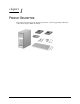
chapter 1 PRODUCT DESCRIPTION This chapter describes the model offerings and features of the Compaq Deskpro EX Series of Personal Computers Minitower Model.
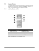
1.1 Computer Features Compaq Deskpro EX Series of Personal Computers Minitower Model ships with a mouse and keyboard. Some models are also equipped with a CD-ROM drive. A Compaq color monitor or other compatible monitor does not ship with the computer. 1.1.1 Front Panel Controls and LEDs Ref. Component/Function Ref.
1.1.2 Rear Panel Connectors Ref. Component Ref.
1.1.3 Drive Positions Reference Drive Bay Configuration 1, 2 1, 2 Two standard 5.25-inch, half-height bays for optional drives 3 3 One standard 3.5-inch, 1.44-MB diskette drive mounted with a drive adapter into a 5.25-inch bay 4, 5 4, 5 Two standard 3.5-inch drive bays; Bay 4 contains the preinstalled hard drive; Bay 5 is available for an optional hard drive Drive bay numbers are stamped on the chassis.
1.2 Serial Number Location The serial number and model information label is located on the access panel of the unit 1. A second barcode label is located on the rear of the unit 2. For the purpose of AssetControl, the serial number is embedded in CMOS and in the EEPROM on the system board and may be accessed through Diagnostics for Windows. If the system board is replaced with a spare part from Compaq, the invalid serial number condition will be recognized during POST.
chapter 2 SPARE PARTS Compaq Deskpro EX and Deskpro EXS Series of Personal Computers 2-1
2.
2.2 Mass Storage Devices Description Spare Part Number Warranty Tier 1 Diskette drive, 3.5-inch 158266-001 D 2 48X Max tray load IDE CD-ROM drive 187263-001 B 3 10.0-GB Ultra ATA hard drive (66/5400) quiet 203139-001 B * 15.0-GB Ultra ATA hard drive (66/5400) 202903-001 B *Not shown (nn/nnnn) = hard drive transfer rate (MBytes/sec)/RPM Ultra ATA/100 hard drives are backwards compatible with Ultra ATA/66 devices; however, the data transfer rate is reduced to 66MB/sec.
2.3 Cables Description Cable Kit includes: 1 Single device, hard drive/CD-ROM cable, 18” (108950-019) 2 Audio cable, 21” (387527-001) * Single device, hard drive/CD-ROM cable, 12.5” (105876-001) * Audio cable, 21”, (288489-002) (not used for this product) 3 Single device, hard drive/CD-ROM cable, 9.
2.4 Standard, Memory, and Expansion Boards Spare Part Number Warranty Tier 1 Nvidia M64 16MB SDRAM AGP Card 182757-001 B 5 AIMM (GPA) 4MB, 133MHz for graphics 192012-001 B 128 MB 170081-001 B 256 MB 192014-001 B Description Memory Module (SDIMM, 133 MHz) 2 Intel Pentium III Processor 3 566/66 MHz with heatsink (191832-002) and clip (223575-007). 203967-001 B * 600/66 MHz with heatsink (191832-002) and clip (223575-007).
2.5 Miscellaneous Plastics Kit Description Spare Part Number Warranty Tier Miscellaneous Plastics Kit, includes: 166878-001 B 1 Panel, sub (166835-001) 2 Bezel, blank (166775-001) 3 Diskette bezel (166776-001) 4 Card guide (166778-001) 5 Foot, rubber (4 ea.) (166939-002) 6 Button, power (166774-001) 7 Drivelock, DT (166779-001) (not used with this product) 8 Spring, power button (166837-001) 9 Springs, drivelock (2 ea.
2.6 2.7 Keyboards (not illustrated) Description Spare Part Number Warranty Tier Easy Access Keyboard-US 123130-xxx D Dutch -331 Finnish -351 French -051 International -B31 Norwegian -091 Spanish -071 Swedish -101 UK -031 US -001 Miscellaneous Screw Kit (not illustrated) Description Spare Part Number Warranty Tier Miscellaneous Screw Kit, includes: 179180-001 D 6-32 x 1/4 hi-top, thread-forming screw with serrations (5 ea.
2.8 2.9 2.
chapter 3 REMOVAL & REPLACEMENT PRELIMINARIES This chapter provides general service information for the computer. Adherence to the procedures and precautions described in this chapter is essential for proper service. CAUTION: When the computer is plugged into an AC power source there is always voltage applied to the system board. You must disconnect the power cord from the power source before opening the computer to prevent system board or component damage. 3.
3.1.2 Preventing Electrostatic Damage to Equipment Many electronic components are sensitive to ESD. Circuitry design and structure determine the degree of sensitivity. The following proper packaging and grounding precautions are necessary to prevent damage to electric components and accessories. 3.1.3 ! To avoid hand contact, transport products in static-safe containers such as tubes, bags, or boxes. ! Protect all electrostatic parts and assemblies with conductive or approved containers or packaging.
3.1.5 ! Use fixtures made of static-safe materials when fixtures must directly contact dissipative surfaces. ! Keep work area free of nonconductive materials such as ordinary plastic assembly aids and Styrofoam. ! Use field service tools, such as cutters, screwdrivers, and vacuums, that are conductive.
3.2.2 Cleaning the Computer Case Follow all safety precautions in Section 3.2.1 before cleaning the computer. To clean the computer case, follow the procedures described below: 3.2.3 ! To remove light stains or dirt, use plain water with a clean, lint-free cloth or swab. ! For stronger stains, use a mild dishwashing liquid diluted with water. Rinse well by wiping it with a cloth or swab dampened with clear water. ! For stubborn stains, use isopropyl (rubbing) alcohol.
3.2.5 Cleaning the Mouse Before cleaning the mouse, ensure that the power to the computer is turned off. 3.3 ! Clean the mouse ball by first removing the retaining plate and the ball from the housing. Pull out any debris from the ball socket and wipe the ball with a clean dry cloth before reassembly. ! To clean the mouse body, follow the procedures in 3.2.2.
3.3.4 Cables and Connectors Most cables used throughout the unit are flat, flexible cables. These cables must be handled with care to avoid damage. Apply only the tension required to seat or unseat the cables during insertion or removal from the connector. Handle cables by the connector whenever possible. In all cases, avoid bending or twisting the cables, and ensure that the cables are routed in such a way that they cannot be caught or snagged by parts being removed or replaced.
chapter 4 REMOVAL AND REPLACEMENT PROCEDURES This chapter provides general service information for the computer. Adherence to the procedures and precautions described in this chapter is essential for proper service. After completing all necessary removal and replacement procedures, run the Diagnostics utility to verify that all components operate properly. 4.1 Disassembly Sequence Chart Use the chart below to determine the disassembly sequence for removing components from the computer. 4.3 4.4 4.
4.2 Disassembly Preparation Before adding any internal options or performing a removal/replacement: 1. Remove any diskette, compact disc, or tape from the computer. 2. Turn off the computer and any peripheral devices that are connected to it. WARNING: Power is continuous to the system board and power supply even when the power switch is turned off. To prevent damage to the unit, disconnect the power cord from the power source or the unit before beginning disassembly procedures.
4.3 Feet Installation Four (4) rubber feet are mounted to the chassis, as shown below. No parts have to be removed to access the feet. The replacement feet have an adhesive surface and are shipped with a protective backing in place. Remove the backing from the feet before installation. If necessary, remove the old feet and remove any adhesive residue from the chassis.
4.4 Cable Lock WARNING: To avoid injury, use care in handling the separated pieces of the cable lock bracket; metal edges may be sharp. Be sure to install the bracket so that sharp edges do not extend from the edges of the computer chassis. Depending on the model, the computer includes a cable lock provision, which consists of a three-piece security bracket. The bottom part of the bracket is attached to the computer with a screw; the top part of the bracket covers the screw and prevents its removal. 1.
4.5 Access Panel 1. Prepare the computer for disassembly (Section 4.2). WARNING: Power is continuous to the system board and power supply even when the power switch is turned off. To prevent damage to the unit, disconnect the power cord from the power source or the unit before beginning disassembly procedures. 2. Lay the computer down on its large base for greater stability. 3. Loosen the two thumbscrews that secure the access panel to the back of the computer chassis. 4.
4.6 Front Bezel 1. Prepare the computer for disassembly (Section 4.2). WARNING: Power is continuous to the system board and power supply even when the power switch is turned off. To prevent damage to the unit, disconnect the power cord from the power source or the unit before beginning disassembly procedures. 2. Remove the access panel (Section 4.5). 3. Press the release tabs 1 on the side of the front bezel. 4. Rotate the front bezel away from the chassis to remove it from the unit 2.
4.7 Power Button 1. Prepare the computer for disassembly (Section 4.2). WARNING: Power is continuous to the system board and power supply even when the power switch is turned off. To prevent damage to the unit, disconnect the power cord from the power source or the unit before beginning disassembly procedures. 2. Lay the computer down on its large base for greater stability. 3. Remove the access panel (Section 4.5). 4. Remove the front bezel (Section 4.6). 5.
4.8 Subpanel and Bezel Blanks The subpanel and bezel blanks must be removed from the front bezel if you are installing a mass storage device for the first time. WARNING: Power is continuous to the system board and power supply even when the power switch is turned off. To prevent damage to the unit, disconnect the power cord from the power source or the unit before beginning disassembly procedures. 1. Prepare the computer for disassembly (Section 4.2). 2.
4.9 Power Switch Assembly CAUTION: The power switch should not be removed from the switch holder. Doing so may damage the switch components. 1. Prepare the computer for disassembly (Section 4.2). WARNING: Power is continuous to the system board and power supply even when the power switch is turned off. To prevent damage to the unit, disconnect the power cord from the power source or the unit before beginning disassembly procedures. 2. Lay the computer down on its large base for greater stability. 3.
4.10 Mass Storage Devices The Compaq Deskpro EX Series of Personal Computers support up to five drives in various configurations. Drive Positions Reference Drive Bay Configuration 12 1, 2 Two standard 5.25-inch, half-height bays for optional drives. 3 3 One standard 3.5-inch, 1.44-MB diskette drive mounted with a drive adapter into a 5.25-inch bay. 45 4, 5 Two standard 3.5-inch drive bays; bay 4 contains the preinstalled hard drive, bay 5 is available for an optional hard drive.
When installing additional drives, follow these guidelines: ! For optimal performance, connect hard drives to the primary controller. Connect expansion devices, such as CD-ROM, IDE tape, and diskette drives to the secondary controller. ! You may install either a third-height or a half-height drive into a half-height bay. ! You must install guide screws to ensure that the drive lines up correctly in the drive cage.
4.10.1 Removing an Internal 3.5-Inch Hard Drive 1. Prepare the computer for disassembly (Section 4.2). 2. Remove the access panel (Section 4.5). 3. Remove the front bezel (Section 4.6). 4. Disconnect the power and data cables from the back of the hard drive. 5. Slide the drivelock mechanism to unlock the hard drives 1. 6. While holding the drivelock in the unlocked position, remove the drive from the drive bay 2. 7. Remove the guide screws from the drive. 8.
4.10.2 Removing an External 5.25-Inch Drive 1. Prepare the computer for disassembly (Section 4.2). WARNING: Power is continuous to the system board and power supply even when the power switch is turned off. To prevent damage to the unit, disconnect the power cord from the power source or the unit before beginning disassembly procedures. 2. Remove the access panel (Section 4.5). 3. Remove the front bezel (Section 4.6). 4. Slide the drivelock mechanism to unlock the drive 1. 5.
4.10.3 Removing an External 3.5-Inch Drive If you are installing a second 3.5-inch diskette drive into 5.25-inch bays #1 or 2 for the first time, you must use a special adapter bracket. If you are installing a 3.5-inch diskette drive into 5.25-inch bay #3, you must use a special adapter bracket. If installing a second ATA hard drive on the primary controller, you must use an 80conductor ATA cable for optimal performance. 1. Prepare the computer for disassembly (Section 4.2).
6. Remove the bracket brace 1 from the top of the drive adapter by squeezing inward on both sides, then rotating the brace up and out. 7. Remove the drive bezel 2. 8. Remove the three screws 3 that secure the drive 4 to the drive adapter. 9. Lift the drive out of the drive adapter. 10. Remove the guide screws from the drive 5. To replace the drive, reverse the previous procedures. ✎ The primary 3.5-inch diskette drive should only be installed into bay 3. Bay 3 is the bottom bay in the minitower.
4.11 Expansion Boards 4.11.
4.11.2 Removing a PCI Expansion Board 1. Prepare the computer for disassembly (Section 4.2). WARNING: Power is continuous to the system board and power supply even when the power switch is turned off. To prevent damage to the unit, disconnect the power cord from the power source or the unit before beginning disassembly procedures. 2. Lay the computer down on its large base for greater stability. 3. Remove the access panel (Section 4.5). 4.
4.11.3 Installing a PCI Expansion Board 1. Prepare the computer for disassembly (Section 4.2). WARNING: Power is continuous to the system board and power supply even when the power switch is turned off. To prevent damage to the unit, disconnect the power cord from the power source or the unit before beginning disassembly procedures. 2. Lay the computer down on its large base for greater stability. 3. Remove the access panel (Section 4.5). 4.
5. Hold the board at each end and carefully rock it back and forth while pushing downward, until the connectors fit completely and firmly into the expansion slot. 6. Secure the board to the chassis with the retaining screw. 7. Attach any cables that came with the board. ✎ If installing a NIC board, attach the WOL power cable to connector P9 on the system board, if applicable. 8. Reassemble the computer. The computer should automatically recognize the added plug and play board.
4.12 System Memory The computer comes with synchronous dynamic random access memory (SDRAM) dual inline memory modules (DIMMs). The Intel 815 chipset comes with at least 64 MB of SDRAM DIMMS, upgradeable to 512 MB. DIMMs The memory sockets on the Intel 815 chipset–based system board can be populated with industry-standard DIMMs. These memory module slots are populated with at least one preinstalled memory module.
To install a memory module, complete the following steps: 1. Prepare the computer for disassembly (Section 4.2). WARNING: Power is continuous to the system board and power supply even when the power switch is turned off. To prevent damage to the unit, disconnect the power cord from the power source or the unit before beginning disassembly procedures. 2. Remove the access panel (Section 4.5). 3. Open both latches of the memory socket ", and insert the memory module into the socket #. 4.
4.13 Graphics Cards The AGP expansion slot may come with a retention mechanism installed around it to hold the graphics cards securely in place. There are two different types of retention mechanisms that may be installed around the AGP expansion slot. 4.13.1 Graphics Performance Accelerator (GPA)/AGP Inline Memory Module (AIMM) Card with a Type I Retention Mechanism Removing a GPA/AIMM Card 1. Prepare the computer for disassembly (Section 4.2).
Installing a GPA/AIMM Card WARNING: Power is continuous to the system board and power supply even when the power switch is turned off. To prevent damage to the unit, disconnect the power cord from the power source or the unit before beginning disassembly procedures. 1. Prepare the computer for disassembly (Section 4.2). 2. Lay the computer down on its large base for greater stability. 3. Remove the access panel (Section 4.5). 4.
6. With the GPA/AIMM card at a 45 degree angle, slide the card toward the back of the expansion slot 4 until the fingers on the bottom of the card line up properly with the connectors in the expansion slot. CAUTION: The fingers on the bottom of the GPA/AIMM card must be properly aligned with the expansion slot during installation. Misalignment may result in damage to the card or the AGP connector. 7.
4.13.2 AGP Card with a Type I Retention Mechanism Removing an AGP Card 1. Prepare the computer for disassembly (Section 4.2). 2. Lay the computer down on its large base for greater stability. 3. Remove the access panel (Section 4.5). 4. Remove the screw at the top of the expansion slot. 5. Pull the arm on the right side of the retention mechanism. 6. Pull the card straight up to remove it from the expansion slot. To install the graphics card, reverse the above procedures.
4.13.3 GPA/AIMM Card with a Type 2 Retention Mechanism Removing a GPA/AIMM Card 1. Prepare the computer for disassembly (Section 4.2). 2. Lay the computer down on its large base for greater stability. 3. Remove the access panel (Section 4.5). 4. Pull the arm on the right side of the retention mechanism. 5. Pull the card straight up to remove it from the expansion slot. To install the graphics card, reverse the above procedures.
4.13.4 AGP Card with a Type 2 Retention Mechanism Removing an AGP Card 1. Prepare the computer for disassembly (Section 4.2). 2. Lay the computer down on its large base for greater stability. 3. Remove the access panel (Section 4.5). 4. Remove the screw at the top of the expansion slot. 5. Pull the arm on the right side of the retention mechanism. 6. Pull the card straight up to remove it from the expansion slot. To install the graphics card, reverse the above procedures.
4.13.5 Standard AGP Expansion Card Removing an AGP Card 1. Prepare the computer for disassembly (Section 4.2). 2. Lay the computer down on its large base for greater stability. 3. Remove the access panel (Section 4.5). 4. Remove the screw at the top of the expansion slot. 5. Remove the AGP graphics board as you would any PCI expansion board (Section 4.11.2).
4.14 Processor 1. Prepare the computer for disassembly (Section 4.2). WARNING: Power is continuous to the system board and power supply even when the power switch is turned off. To prevent damage to the unit, disconnect the power cord from the power source or the unit before beginning disassembly procedures. 2. Remove the computer cover (Section 4.3). 3. If there is a fansink on the processor, unplug the fan cable from the system board. 4.
Before installing a fansink, prepare for its installation by doing one of the following: • New heatsink: if the heatsink has a thermal interface attached to its bottom, peel off the protective paper before installing the heatsink, if necessary. • Reinstalled heatsink: Note where the thermal interface is located on the heatsink. Carefully remove the thermal interface pad and all residue from the heatsink surface.
4.15 System Board ✎ More information on the system board, including troubleshooting criteria, can be found in the Compaq Quick Troubleshooting Guide (part number 153837-001) and the Compaq Service Reference Guide (part number 152611-001). 1. Prepare the computer for disassembly (Section 4.2). WARNING: Power is continuous to the system board and power supply even when the power switch is turned off.
4.16 Battery 1. Prepare the computer for disassembly (Section 4.2). 2. Lay the computer down on its large base for greater stability. 3. Remove the access panel (Section 4.5). 4. Locate the battery on the system board. If you have expansion boards installed, you may need to remove them to gain access to the battery (Section 4.11.2). 5. Lift the battery out of the holder. 6. Slide the replacement battery into position with the positive side up.
4.17 Chassis Fan Assembly ✎ If the unit has a 866 - 933MHz processor, it requires an external chassis fan. 1. Prepare the computer for disassembly (Section 4.2). WARNING: Power is continuous to the system board and power supply even when the power switch is turned off. To prevent damage to the unit, disconnect the power cord from the power source or the unit before beginning disassembly procedures. 2. Remove the access panel (Section 4.5). 3. Disconnect the fan power cable 1 from the system board. 4.
4.18 Power Supply 1. Prepare the computer for disassembly (Section 4.2). WARNING: Power is continuous to the system board and power supply even when the power switch is turned off. To prevent damage to the unit, disconnect the power cord from the power source or the unit before beginning disassembly procedures. 2. Lay the computer down on its large base for greater stability. 3. Remove the access panel (Section 4.5). 4. Disconnect all power cables from the mass storage devices and the system board.
chapter 5 CONNECTORS AND JUMPERS This chapter provides connector, jumper, and switch information for system board jumpers, system I/O board connectors, and hard drives for the Desktop Model. 5.1 System Board 5.1.1 Connectors and Jumpers CR28 CR29 3.3V Aux LED P12 SOS Connector 3.
5.1.2 Clearing CMOS The computer's configuration (CMOS) may occasionally be corrupted. If it does, it is necessary to clear the CMOS memory using push button switch SW50. To clear and reset the configuration, perform the following procedure: 1. Prepare the computer for disassembly (Section 4.2). CAUTION: The power cord must be disconnected from the power source before pushing the Clear CMOS Button (NOTE: All LEDs on the board should be OFF). Failure to do so may damage the system board. 2.
5.1.3 Disabling or Clearing the Power-On and Setup Passwords 1. Turn off the computer and any external devices, and disconnect the power cord from the power outlet. 2. Disconnect the keyboard, monitor, and any other external devices connected to the computer. 3. Remove the computer cover. 4. Locate the header and jumper labeled E49. 5. Remove the jumper from pins 1 and 2. Place the jumper over pin 2 only, in order to avoid losing it. 6. Replace the computer cover. 7. Reconnect the external equipment. 8.
5.2 Hard Drive Jumper Settings 5.2.1 Seagate, Quantum, and Western Digital The drawings and tables below apply to a number of different size drives in the following paragraphs.
5.2.
chapter 6 SPECIFICATIONS 6.1 Specifications 6.1.1 System Dimensions Height Width Depth 17.65 in 6.60 in 16.80 in 44.83 cm 16.76 cm 42.67 cm Weight (approximate, depending on configuration) 26 lb 11.8 kg 90-132 Vac 120-127 Vac 47-63 Hz 5.
6.1.2 6.1.
6.1.4 ICH Fixed I/O Registers Port Register Name 00h, 02h, 04h, 06h Channel 0, 1, 2, 3 DMA Base & Current Address Regsiter C0h, C4h, C8h, CCh Channel 4, 5, 6, 7 DMA Base & Current Address Register 01h, 03h, 05h, 07h Channel 0, 1, 2, 3 DMA Base & Current Count Register C2h, C6h, Cah, CEh Channel 4, 5, 6, 7 DMA Base & Current Count Register 10h-1Fh Aliased at 00h-0Fh 20h Master PIC ICW1 Init.
ICH Fixed I/O Registers cont Port Register Name CF9h A0h Reset Control Register Slave PIC ICW1 Init. Cmd Word 1 Register Slave PIC OCW2 Op Ctrl Word 2 Register Slave PIC OCW3 Op Ctrl Word 3 Register A1 Slave PIC ICW2 Init. Cmd Word 2 Register Slave PIC ICW3 Init. Cmd Word 3 Register Slave PIC ICW4 Init.
ICH Fixed I/O Registers cont Port Register Name 1F0h-1F7h PIO Mode Command Block Offset for Primary Drive 376h PIO Mode Control Block Offset for Secondary Drive 3F6h PIO Mode Control Block Offset for Primary Drive 4D0h Master PIC Edge/Level Triggered Register 3F6h PIO Mode Control Block Offset for Primary Drive 4D0h Master PIC Edge/Level Triggered Register 4D1h Slave PIC Edge/Level Triggered Register 400-47F Super I/O F800-F87F Reserved (power management) FA00-FA3F Reserved (GPIO manageme
6.2 Drives 6.2.1 1.44-MB Diskette Drive 6-6 Size and Capacity Size (in) High Density (MB) Low Density (KB) 3.5 1.
6.2.2 Ultra ATA Hard Drives 10.0 GB 15.
6.2.3 CD-ROM Drives 48X Max Compaq Spare Part Number 187263-001 Data Buffer (ms) 16.
6.3 Compaq Keyboard Compaq Easy Access Dimensions Height Width Depth 6.4 1.4 in 18.3 in 6.3 in Scroll Mouse Dimensions Height Length Width 1.34 in 4.45 in 2.36 in 3.4 cm 11.3 cm 6.0 cm Weight 4.59 oz 130 g Base Resolution 400 dpi 15.
6.5 Supported Graphics Resolutions 6.5.1 Intel 3D Graphics 6.5.2 6-10 Colors 256 65K 16.
Index A access panel removal and replacement, 4-5 AGP card spare part number, 2-3 AGP retention mechanism, 4-22 AIMM card spare part number, 2-3 B battery proper disposal, 4-32 removal and replacement, 4-32 C cable kit spare part number, 2-2 cable lock removal and replacement, 4-4 cable select feature, 4-11 CD-ROM specifications, 6-8 CD-ROM drive spare part number, 2-2 cleaning computer, 3-4 keyboard, 3-4 monitor, 3-4 mouse, 3-5 clearing CMOS, 5-2 clearing passwords, 5-3 CMOS clearing configuration, 5-2 c
M memory removal and replacement, 4-20 spare part number, 2-3 standard, 2-3 memory map, 6-5 microprocessor spare part number, 2-3 miscellaneous screw kit spare part number, 2-4 monitor cleaning, 3-4 mouse cleaning, 3-5 spare part number, 2-5 specifications, 6-9 N Network Interface Card spare part number, 2-3 Nvidia graphics card spare part number, 2-3 P passwords, 5-3 power button removal and replacement, 4-7 power supply fan, 3-5 removal and replacement, 4-34 spare part number, 2-1 power switch removal a