MSM800XEV with thermojunction MSM800XEL MSM800XEV/XEL Document Revision 100 Draft If it's embedded, it's Kontron.
» Table of Contents « 1 User Information............................................................................ 6 1.1 About this Document ...............................................................................................................6 1.2 Copyright Notice .....................................................................................................................6 1.3 Trademarks ..............................................................................................
.3 The LANCON, Part Nr. 803046................................................................................................... 19 4.4 The DVICON, Part Nr. 803042 ................................................................................................... 20 4.5 Connect Peripherals to the Board.............................................................................................. 21 4.6 Power Up the Board ...............................................................................
6.3 High Frequency Radiation (to meet EN55022) ............................................................................. 40 6.3.1 For Peripheral Cables: ........................................................................................................... 40 6.3.2 For Stack-Through Applications:.............................................................................................. 41 6.3.3 Power Supply: ..................................................................................
7.2 VGA/LCD ............................................................................................................................. 60 7.2.1 VGA/LCD Controller of the Geode LX800 .................................................................................... 60 7.2.2 Graphic Modes..................................................................................................................... 60 7.2.3 DVICON Resolution ....................................................................
8.3.3 MSM800XEV V1.1, Top, XPe burn-in test PRO (50% load) ............................................................... 81 8.4 Thermal Specifications ........................................................................................................... 82 9 BIOS...........................................................................................84 9.1 BIOS History ........................................................................................................................
MSM800XEV/XEL / User Information 1 User Information 1.1 About this Document This document provides information about products from Kontron AG and/or its subsidiaries. No warranty of suitability, purpose, or fitness is implied. While every attempt has been made to ensure that the information in this document is accurate, the information contained within is supplied "as-is" and is subject to change without notice.
MSM800XEV/XEL / User Information 1.6 Technical Support Technicians and engineers from Kontron AG and/or its subsidiaries are available for technical support. We are committed to making our products easy to use and will help you use our products in your systems. Please consult our Web site at http://www.kontron.com/support for the latest product documentation, utilities, drivers and support contacts. Consult our customer section http://emdcustomersection.kontron.
MSM800XEV/XEL / User Information 1.8.1 RoHS Compatible Product Design All Kontron Compact Computers (KCC) AG standard products comply with RoHS legislation. Since July 1, 2006, there has been a strict adherence to the use of RoHS compliant electronic and mechanical components during the design-in phase of all KCC AG standard products. 1.8.2 RoHS Compliant Production Process Kontron Compact Computers AG selects external suppliers that are capable of producing RoHS compliant devices.
MSM800XEV/XEL / User Information 1.10 The Swiss Association for Quality and Management Systems The Swiss Association for Quality and Management Systems (SQS) provides certification and assessment services for all types of industries and services. SQS certificates are accepted worldwide thanks to accreditation by the Swiss Accreditation Service (SAS), active membership in the International Certification Network, IQNet, and co-operation contracts/agreements with accredited partners. www.sqs.
MSM800XEV/XEL / Introduction 2 Introduction 2.1 MSM800XEV/XEL Ordering Information Part / Option Part Nr.
MSM800XEV/XEL / Introduction 2.
MSM800XEV/XEL / Introduction 2.4 Block Diagrams 2.4.1 MSM800XEV 2.5 MICROSPACE® Documentation This manual is written for the original equipment manufacturer (OEM) who plans to build computer systems based on the single board MICROSPACE-PC. It is for integrators and programmers of systems based on the MICROSPACEComputer family. This manual provides instructions for installing and configuring the board and describes the system and setup requirements.
MSM800XEV/XEL / Introduction 2.6 Product Photos 2.6.1 MSM800XEL The MSM800XEL differs from the MSM800XEV in that it has no battery. Top View: Bottom View: 13 www.kontron.
MSM800XEV/XEL / Introduction 2.6.2 MSM800XEV Top View, with Option 807041 (small cooler): Bottom View: 14 www.kontron.
MSM800XEV/XEL / Specifications 3 Specifications Note: All information is subject to change without notice. CPU CPU CPU Core Supply Mode Compatibility Word Size Secondary Cache Physical Addressing Virtual Addressing Clock Rates Socket Standard Geode LX800 1.8V very low powered Real/Protected 8086 – P5 32bits – 32 lines 16GBytes 500MHz Soldered BGA Chipset Northbridge Southbridge LAN Audio Firewire IEEE1394 Video AMD LX800 AMD 5536 10/100Mbit Intel 82C551ER AC97 – V2.
MSM800XEV/XEL / Specifications Video Controller Bus Enhanced BIOS Memory CRT-Monitor Flat Panel Controller Modes Video Input Drivers MSM800XEV/XEL 32bit high speed 33MHz PCI bus VGA/LCD BIOS 2-254MByte shared RAM VGA, SVGA up to 1920x1440 TFT 3.3V 18/24bit up to 1600x1200 CRT only; flat panel only; or simultaneous CRT and flat panel No WIN2000, XP Mass Storage FD HD Floppy disk interface, for max. 1 floppy with 26pin connector E-IDE interface, AT-type, for max. 2 hard disks, 44pin connector, for 1.3, 1.
MSM800XEV/XEL / Specifications Power Supply Working Power Rise Time Power Consumption Standby Power Consumption 5 Volts ± 5% Unspecified MSM800XEV with HD, MS/KB (PS/2), CRT monitor, WindowsXP Desktop: MSM800XEV/XEL: Windows Standby: 2.5W (without MS/KB wake-up function) Windows Standby: 4.5W (with PS/2 wake-up function) typ. 7.5-10W Physical Characteristics Dimensions Weight PCB Thickness PCB Layer Length: 90mm Depth: 96/99mm Height: 17-25mm 90-170gr depending on model and cooler option 1.6mm / 0.
MSM800XEV/XEL / Quick Start Guide 4 Warning: 4.1 Quick Start Guide ESD Sensitive Device! Place the embedded computer board on an isolated, ESD-protected surface. Ensure that all equipment, tools and people are fully protected against ESD. Print Manuals from the Product CD Place the Product CD into the CD drive of a personal computer with a connected printer. Open the CD; open the directory Manuals/MSM800. Print out the required manuals (for example the BIOS manual or the User's Guide). 4.
MSM800XEV/XEL / Quick Start Guide The MSM800CON connected to an MSM800BEV board: 4.3 19 The LANCON, Part Nr. 803046 www.kontron.
MSM800XEV/XEL / Quick Start Guide 4.4 The DVICON, Part Nr. 803042 The DVICON connected to an MSM800BEV board: 20 www.kontron.
MSM800XEV/XEL / Quick Start Guide 4.5 Connect Peripherals to the Board Prepare the following peripherals: » VGA monitor (LCD or CRT) with a resolution up to 1024x768 pixel » PS2 keyboard » USB mouse » LAN cable, if available » Hard disk or CompactFlash » USB CD drive or floppy drive » Power supply with 5 Volts and min. 30 Watts Make sure the polarity is correct. Otherwise the hard disk and/or electronic board may be destroyed. 1. Connect the VGA monitor to the 15pin high density DSub-connector. 2.
MSM800XEV/XEL / Quick Start Guide MSM800SEV with the contents of the Cable Kit (CKCON): All of the above cables and PCB connectors are included in the MSM800CKCON, Part Nr. 803035 (the MSM800 board is not included). 22 www.kontron.
MSM800XEV/XEL / Quick Start Guide 4.6 1. Power Up the Board Check that the voltage is regulated to +5Volt and that the polarity is correct. Attention! The supply voltage must be in the range of 4.9Volt to maximum 5.25Volt. 2. Switch on the connected monitor. 3. Switch on the external 5V power supply. Attention! Jumper J1 determines the mode of the CompactFlash disk. J1 – CF Master 23 www.kontron.
MSM800XEV/XEL / Quick Start Guide Attention! Jumper J2 determines the behavior after power-on. J2 – Autostart In autostart mode the board will automatically enter the boot sequence and the green "Power LED" will turn on. In non-autostart mode the board will remain in standby mode until the power button is pressed. 24 www.kontron.
MSM800XEV/XEL / Quick Start Guide After a few seconds the screen should display the BIOS initial message/picture: 25 www.kontron.
MSM800XEV/XEL / Quick Start Guide 4.7 BIOS Setup Since the BIOS is auto-configuring during the start-up procedure, the user normally does not enter the BIOS setup. Manual setup is needed only to change the default settings. Please refer to the driver/software/BIOS manual printed from the Product CD for the BIOS setup details. Note: For the MSM800SEL/XEL: The RTC clock and date must be adjusted in the BIOS setup after the external battery is connected to the board. 4.
MSM800XEV/XEL / Connectors & Jumpers 5 Connectors & Jumpers 5.1 Connectors The following pages describe the connector pin-out for all current MSM800 boards. Flat cable 44pin IDE is: All others are: NC: IDT Terminal for Dual Row (2.00mm grid) and 1.00mm flat cable IDT Terminal for Dual Row 0.1" (2.54mm grid) and 1.27mm flat cable not connected Connector Structure Pin Remarks X1 Power 2x4 2.54mm X10 VGA 2x5 2.54mm X15 LCD 2x22 2mm X29 Sound Audio I/O 2x15 2.00mm X30 LPT1 2x13 2.
MSM800XEV/XEL / Connectors & Jumpers 5.1.1 Top Side of the MSM800XEV/XEL V1.2/1.1 The XEL model does not have a battery (BT1). 28 www.kontron.
MSM800XEV/XEL / Connectors & Jumpers 5.1.2 Bottom Side of the MSM800XEV/XEL V1.2/1.1 With CompactFlash (Option 807007, connector X71). 29 www.kontron.
MSM800XEV/XEL / Connectors & Jumpers 5.1.3 X1 Power Supply Pin Signal Pin Signal 1 3 5 7 GND NC NC GND 2 4 6 8 VCCSUS +5Volt Input Supply (+12V input) Main_SW (Push button to switch on the board if J2 is open) VCCSUS +5Volt Input Supply VCCSUS = 5Volt Main Supply Input 2 4 6 8 1 3 5 7 Pin placement: 5.1.
MSM800XEV/XEL / Connectors & Jumpers 5.1.5 X15 LCD TFT Interface (flat panel signals) Pin Signal TFT 18bit TFT 24bit 1 2 3 4 5 6 7 8 9 10 11 12 13 14 15 16 17 18 19 20 21 22 23 24 25 26 27 28 29 30 31 32 33 34 35 36 37 38 39 40 41 42 43 44 FPM (out) CRT-Vert.Synch Backlight Supply output (5/12V) CRT-Horiz.Synch VCC 3.
MSM800XEV/XEL / Connectors & Jumpers 5.1.
MSM800XEV/XEL / Connectors & Jumpers 5.1.8 X31 Keyboard PS/2/-Mouse Utility Connector The speaker must be connected to VCC, to have a low, inactive current in the speaker. Pin Signal Pin Signal 1 3 5 7 9 Speaker Out Reset In (active low) Keyboard Data Ground PS/2 Mouse Clock 2 4 6 8 10 Ground (for Speaker) VCC Keyboard Clock External Battery PS/2 Mouse Data Reset-In signal has an internal Pullup of 1k to 5Volt VCC.
MSM800XEV/XEL / Connectors & Jumpers 5.1.9 X33 10/100 BASE-T Interface Connector Pin Signal 1 2 3 4 5 6 7 8 9 10 TXTX+ RXRX+ Activity LED BAT Input 3.0-3.6V GND VCC 3.3V Speed LED Link LED 5.1.10 Remarks The LAN transformer is onboard starting with board version: XEV/XEL V0.1 External lithium battery (see also Section 6.4.
MSM800XEV/XEL / Connectors & Jumpers 5.1.12 X44 IrDA Connector Pin Signal 1 2 3 4 VCC IRTX IRRX GND BIOS settings: You must enable the UART A of the GeodeLX in the BIOS setup: » F1 Mother board device configuration I/O configuration: » UART port A = enabled » UART mode = SIR/CIR Never set the UART A mode to "Serial-16550 compatible" or "Extended" when an IrDA diode is connected to the X44 or the diode will be destroyed! 5.1.13 X50 USB 1 Connector Pin Signal 1 2 3 4 VCC USB-P0USB-P0+ GND 5.1.
MSM800XEV/XEL / Connectors & Jumpers 5.1.17 X60 IDE Interface Pin Signal Pin Signal 1 3 5 7 9 11 13 15 17 19 21 23 25 27 29 31 33 35 37 39 41 43 Reset (active low) D7 D6 D5 D4 D3 D2 D1 D0 GND DREQ IOW (active low) IOR (active low) IORDY DACK IRQ14 ADR1 ADR0 CS0 (active low) LED (active low) asp VCC Logic GND 2 4 6 8 10 12 14 16 18 20 22 24 26 28 30 32 34 36 38 40 42 44 GND D8 D9 D10 D11 D12 D13 D14 D15 (keypin) NC GND GND GND SPSYNC GND NC PDIAG ADR2 CS1 (active low) GND VCC Motor NC 5.1.
MSM800XEV/XEL / Connectors & Jumpers 5.1.19 X101 PC/104+ BUS Interface Pin A B C D 1 2 3 4 5 6 7 8 9 10 11 12 13 14 15 16 17 18 19 20 21 22 23 24 25 26 27 28 29 30 GND/5.0V KEY2 VI/O AD05 C/BE0 GND AD11 AD14 +3.3V SERR GND STOP +3.3V FRAME GND AD18 AD21 +3.3V IDSEL0 AD24 GND AD29 +5V REQ0 GND GNT1 +5V CLK2 GND +12V NC Reserved AD02 GND AD07 AD09 VI/O AD13 C/BE1 GND NC +3.3V TRDY GND AD16 +3.
MSM800XEV/XEL / Connectors & Jumpers 5.1.20 X102 PC/104 BUS Interface Pin A: B: 0 1 2 3 4 5 6 7 8 9 10 11 12 13 14 15 16 17 18 19 20 21 22 23 24 25 26 27 28 29 30 31 32 IOCHCK SD7 SD6 SD5 SD4 SD3 SD2 SD1 SD0 IOCHRDY AEN SA19 SA18 SA17 SA16 SA15 SA14 SA13 SA12 SA11 SA10 SA9 SA8 SA7 SA6 SA5 SA4 SA3 SA2 SA1 SA0 Ground Ground RESET +5Volt IRQ9 NC DRQ2 (-12Volt) 0WS +12Volt Ground NC SMEMW SMEMR SIOW SIOR DACK3 DRQ3 DACK1 DRQ1 REF SYSCLK IRQ7 IRQ6 IRQ5 IRQ4 IRQ3 DACK2 TC ALE +5Volt OSC Ground Ground 5.
MSM800XEV/XEL / Connectors & Jumpers 5.2 Jumpers The following table shows the location of all jumper blocks on the MSM800 board. The numbers shown in this figure are silk screened on the board so that the pins can easily be located. This section refers to the individual pins for these jumpers. The default jumper settings are written in bold. Attention! Some jumpers are soldering bridges; you will need a miniature soldering station with a vacuum pump. 5.2.
MSM800XEV/XEL / Detailed System Description 6 Detailed System Description This system's configuration is based on the ISA architecture. Check the I/O and the Memory maps in this Chapter. 6.1 Incompatibilities to a Standard PC/AT 6.1.1 PC104 BUS / ISA BUS An onboard LPC to ISA-bridge makes it possible to expand the functionality of the board with additional PC/104 cards. Unfortunately, because of the transformation from LPC to ISA it is not possible to realize a 16bit access.
MSM800XEV/XEL / Detailed System Description 6.3.2 For Stack-Through Applications: On each peripheral signal line that goes outside the computer case, place a serial inductivity followed by a grounded capacitor of 100pF to 1000pF. In this case, no filtered connectors are needed. Place the filter directly under or behind the onboard connector. Serial Inductivity TDK HF50ACB321611-T 100MHz, 500mA, 1206 Case Ground Capacitor Ceramic Capacitor with 1000pF 6.3.
MSM800XEV/XEL / Detailed System Description 6.5 Power Requirements The power is connected through the PC/104 power connector; or the separate power connector on the board. The supply uses only +5Volts and a ground connection. Attention: Be sure the power plug is wired correctly before supplying power to the board! A built-in diode protects the board against reverse polarity.
MSM800XEV/XEL / Detailed System Description 6.7.3 DDRAM Memory on MSM800XEV/XEL Speed Size Bits Capacity Bank 6.8 333 DDR-Chips (BGA) 64bit 256MByte 1 Interfaces 6.8.1 AT Compatible Keyboard & PS/2 Mouse X31 Pin Signal 1 2 3 4 5 6 7 8 9 10 Speaker out GND External reset input VCC Keyboard Data Keyboard Clock GND Battery Mouse Clock (PS/2) Mouse Data (PS/2) BAT input 3.0-3.6V, external lithium battery (see also Section 6.4.1). 6.8.
MSM800XEV/XEL / Detailed System Description 6.8.4 Floppy Disk Interface The onboard floppy disk controller and ROM-BIOS support one or two floppy disk drives in any of the standard PC-DOS and MS-DOS formats shown in the table. Supported Floppy Formats: Capacity Drive Size Tracks Data Rate DOS Version 1.2MB 720K 1.44M 5¼" 3½" 3½" 80 80 80 500KHz 250KHz 500KHz 3.0 - 6.22 3.2 - 6.22 3.3 - 6.
MSM800XEV/XEL / Detailed System Description 6.8.5 Speaker Interface One of the board's CPU devices provides the logic for a PC compatible speaker port. The speaker logic signal is buffered by a transistor amplifier, and provides approximately 0.1 Watt of audio power to an external 8 Ohm speaker. Connect the speaker between VCC and speaker output to have no quiescent current. 6.9 Controllers 6.9.
MSM800XEV/XEL / Detailed System Description 6.10.2 RTC (Real Time Clock) An AT compatible date/time clock is located within the chipset. The device also contains a CMOS static RAM, compatible with that in standard ATs. System configuration data is normally stored in the clock chip's CMOS RAM in a manner consistent with the convention used in other AT compatible computers. Connect an external lithium battery to X33 pin6 (or use the mounted battery).
MSM800XEV/XEL / Detailed System Description 6.11.
MSM800XEV/XEL / Detailed System Description Location 10h 11h 12h 13h 14h 15h 16h 17h 18h 19h 1Ah 48 Description Diskette Drives Bits 7-4 = Diskette Drive A 0000 = Not installed 0001 = Drive A = 360 kB 0010 = Drive A = 1.2MB 0011 = Drive A = 720 kB 0100 = Drive A = 1.44MB 0101 = Drive A = 2.88MB Bits 3-0 = Diskette Drive B 0000 = Not installed 0001 = Drive B = 360 kB 0010 = Drive B = 1.2MB 0011 = Drive B = 720 kB 0100 = Drive B = 1.44MB 0101 = Drive B = 2.
MSM800XEV/XEL / Detailed System Description Location 1Bh 1Ch 1Dh 1Eh 1Fh - 24h 1Fh 20h 21h 22h 23h 24h 25h - 2Ah 25h 26h 27h 28h 29h 49 Description Custom and Fixed (Hard) Drive Flags Bits 7-6 = Reserved Bit 5 = Internal Floppy Disk Controller 0 = Disabled 1 = Enabled Bit 4 = Internal IDE Controller 0 = Disabled 1 = Enabled Bit 3 = Hard Drive 0 Custom Flag 0 = Disabled 1 = Enabled Bit 2 = Hard Drive 0 IDE Flag 0 = Disabled 1 = Enabled Bit 1 = Hard Drive 1 Custom Flag 0 = Disabled 1 = Enabled Bit
MSM800XEV/XEL / Detailed System Description Location 2Ah 2Bh 2Ch 2Dh 2Eh 2Fh 30h 31h 32h 33h 34h 35h 36h 40h-7Fh Description Byte 5 Bits 7-0 = Sectors Per Track Boot Password Bit 7 = Enable/Disable Password 0 = Disable Password 1 = Enable Password Bits 6-0 = Calculated Password SCU Password Bit 7 = Enable/Disable Password 0 = Disable Password 1 = Enable Password Bits 6-0 = Calculated Password Reserved High Byte of Checksum - Locations 10h to 2Dh Low Byte of Checksum - Locations 10h to 2Dh Extended R
MSM800XEV/XEL / Detailed System Description If the system hangs or a problem appears, the following steps must be performed: 1. 2. 3. 4. Reset the CMOS-Setup (disconnect the battery for at least 10 minutes). Press ESC until the system starts up. Enter the BIOS Setup: a. load DEFAULT values b. enter the settings for the environment c. exit the setup Restart the system. The user may access the EEPROM through the INT15 special functions.
MSM800XEV/XEL / Detailed System Description CPU GEODE: Address Size 000000 - 09FFFFh 0A0000 - 0BFFFFh 0C0000 - 0C7FFFh 0C8000 - 0CFFFFh 0D0000 - 0DFFFFh 0E0000 - 0EBFFFh 0EC000 - 0EFFFFh 0F0000 - 0FFFFFh 100000 - 1FFFFFFh 640kByte 128kByte 32kByte 32kByte 64kByte 32kByte 16kByte 64kByte 31MByte Function / Comments Onboard DRAM for DOS applications CGA, EGA, LCD Video RAM 128kB VGA BIOS Free for user Free for user BIOS BIOS extensions Core BIOS DRAM for extended onboard memory 6.13.
MSM800XEV/XEL / Detailed System Description I/O Address Function Size R/W 022h-03Fh 040h 041h 042h 043h 044h-05Fh No specific usage PIT – System Timer PIT – Refresh Timer PIT – Speaker Timer PIT – Control No specific usage --8bit 8bit 8bit 8bit --- --Shw$ Shw$ Shw$ Shw$ --- 060h Keyboard/Mouse - Data Port 8bit Yes 061h 062h-063h Port B Control No specific usage 8bit --- Yes --- Comment If KEL Memory Offset 100h[0] = 1 (Emulation-enabled bit).
MSM800XEV/XEL / Detailed System Description I/O Address Function Size R/W 0CDh 0CEh 0CFh 0D0h 0D1h 0D2h 0D3h 0D4h 0D5h 0D6h 0D7h 0D8h 0D9h 0DAh 0DBh 0DCh 0DDh 0DEh 0DFh 0E0h-2E7h No specific usage Master DMA Counter - Channel 7 No specific usage Master DMA Command/Status – Channels [7:4] No specific usage Master DMA Request - Channels [7:4] No specific usage Master DMA Mask - Channels [7:4] No specific usage Master DMA Mode - Channels [7:4] No specific usage Master DMA Clear Pointer - Channels [7:4] No
MSM800XEV/XEL / Detailed System Description I/O Address Function Size R/W Comment 481h DMA Channel 2 High Page 8bit Rec Upper addr bits [31:24]. Write LPC and DMA. Read only DMA.
MSM800XEV/XEL / System Resources 7 System Resources 7.1 Bus Signals 7.1.1 PC104 Bus Note: Not all of the signals are available on this board (please see Chapter 5 for a description of the connectors). AEN, output Address Enable: used to degate the microprocessor and other devices from the I/O channel to allow DMA transfers to take place.
MSM800XEV/XEL / System Resources /Master, input This signal is used with a DRQ line to gain control of the system. A processor or DMA controller on the I/O channel may issue a DRQ to a DMA channel in cascade mode and receive a /DACK. /MEMCS16, input MEMCS16 Chip Select: signals the system board if the present data transfer is a 1 wait-state, 16bit, memory cycle. It must be derived from the decode of LA17 through LA23.
MSM800XEV/XEL / System Resources /SMEMW, input/output These signals instruct the memory devices to store the data present on the data bus for the first MByte. /SMEMW is active in all memory read cycles. /SMEMW may be driven by any microprocessor or DMA controller in the system. When a microprocessor on the I/O channel wishes to drive /SMEMW, it must have the address lines valid on the bus for one system clock period before driving /SMEMW active. Both signals are active low.
MSM800XEV/XEL / System Resources DEVSEL* Device Select is driven by the target device when its address is decoded. IDSEL Initialization Device Select is used as a chip-select during configuration. LOCK* Lock indicates an operation that may require multiple transactions to complete. PERR* Parity Error is for reporting data parity errors. SERR* System Error is for reporting address parity errors. REQ* Request indicates to the arbitrator that this device desires use of the bus.
MSM800XEV/XEL / System Resources 7.1.4 Addressing PCI Devices MSM800XEV/XEL V1.x (4 PCI slots available) DEVICE IDSEL PIRQ #REG #GNT Remarks SLOT 1 SLOT 2 SLOT 3 SLOT 4 LAN PCI-ISA-Bridge AD20 AD21 AD22 AD23 AD29 AD24 A/B/C/D B/C/D/A C/D/A/B D/A/B/C A 3 4 5 6 7 8 3 4 5 6 7 8 For additional cards (peripheral boards) For additional cards (peripheral boards) For additional cards (peripheral boards) For additional cards (peripheral boards) Onboard devices 7.2 VGA/LCD 7.2.
MSM800XEV/XEL / System Resources 7.2.4 Flat Panel Functional Description The FP connects to the RGB port of the video mixer. LCD Interface: The FP interfaces directly to industry standard 18 or 24bit active matrix thin-film-transistor (TFT). The digital RGB or video data that is supplied by the video logic is converted into a suitable format to drive a wide variety range of panels with variable bits.
MSM800XEV/XEL / System Resources 7.3 Cable Interfaces 7.3.1 The Hard Disk Cable 44pin IDT Terminal for Dual Row (2.00mm grid) and 1.00mm flat cable; 44pins = 40pins signal and 4pins power. 1 2 39 1 2 40 43 44 39 40 43 44 Maximum length for the IDE cable is 30cm. Attention: Check the pin1 marking on the cable and the connector before powering-on. Refer to the technical manual of the installed drives because a wrong cable will immediately destroy the drive and/or the MICROSPACE MSM800 board.
MSM800XEV/XEL / System Resources 7.3.2 The COM 1/2 Serial Cable DT terminal for dual row 0.1" (2.54 mm grid) and 1.27 mm flat cable. Line of pin 1 1 2 6 7 8 9 COM1/2 Attention: 9 1 2 COM1 9pin D-Sub male 3 4 5 10 Do not short circuit these signal lines. Never connect any pins on the same plug or to any other plug on the MICROSPACE MSM800. The +/10Volts will destroy the MICROSPACE core logic immediately.
MSM800XEV/XEL / System Resources 7.3.4 The Micro-Floppy Cable 64 www.kontron.
MSM800XEV/XEL / System Resources 7.3.5 The LAN Cable (RJ45) Attention: Early board versions use the MSM855-LANCON. Later versions must use the MSM800-LANCON, because the LAN transformer (pulse) is integrated on the MSM800 product. See below for the version numbers. Use the MSM800-LANCON starting with the following versions: XEV/XEL Version 0.1 For earlier versions use the MSM855-LANCON: RJ45 connector 10BaseT (IEEE 802.3i), 100BaseTX (IEEE 802.3u): MDI-Pin TX+ TXRX+ GND .. GND .. RXGND .. GND ..
MSM800XEV/XEL / Design Considerations 8 Design Considerations 8.1 Dimensions and Diagrams 8.1.1 MSM800XEV/XEL Board / Version Unit Tolerance Date / Author MSM800XEV mm (millimeter) + / - 0.1mm 19.03.2008 / BRR 66 www.kontron.
MSM800XEV/XEL / Design Considerations 8.1.2 Top of XEV board (XEL does not have a battery) 8.1.3 XEV board profile with CompactFlash (Option 807007) and battery (not on XEL) 67 www.kontron.
MSM800XEV/XEL / Design Considerations 8.1.4 3D perspective, top of XEV board (XEL does not have a battery) 8.1.5 3D perspective, bottom of XEV/XEL board with L+ (Option 807006) 68 www.kontron.
MSM800XEV/XEL / Design Considerations 8.1.6 Top of XEV board with small heat sink (Option 807041) and battery (not on XEL) 8.1.7 XEV board profile with small heat sink (Option 807041), CompactFlash (Option 807007) and battery (not on XEL) 69 www.kontron.
MSM800XEV/XEL / Design Considerations 8.1.8 3D perspective, top of XEV board with small heat sink (Option 807041) and battery (not on XEL) 8.1.9 Top of XEV with large heat sink (Option 807042) and battery (not on XEL) 70 www.kontron.
MSM800XEV/XEL / Design Considerations 8.1.10 XEV board profile with large heat sink (Option 807042), CompactFlash (Option 807007) and battery (not on XEL) 8.1.11 3D perspective, top of XEV with large heat sink (Option 807042) and battery (not on XEL) 71 www.kontron.
MSM800XEV/XEL / Design Considerations 8.1.12 Top of XEV board with thermojunction (Option 807043) and battery (not on XEL) 8.1.13 XEV board profile with thermojunction (Option 807043), CompactFlash (Option 807007) and battery (not on XEL) 72 www.kontron.
MSM800XEV/XEL / Design Considerations 8.1.14 3D perspective, top of XEV with thermojunction (Option 807043) and battery (not on XEL) 73 www.kontron.
MSM800XEV/XEL / Design Considerations 8.1.15 MSM800LVDSCON Board / Version Unit Tolerance Date / Author MSM800-LVDSCON V0.1 mm (millimeter) + / - 0.1mm 25.10.2006 / BRR 74 www.kontron.
MSM800XEV/XEL / Design Considerations 8.1.16 MSM800DVICON Board / Version Unit Tolerance Date / Author MSM800-DVICON V0.1 mm (millimeter) + / - 0.1mm 25.10.2006 / BRR 75 www.kontron.
MSM800XEV/XEL / Design Considerations 8.1.17 MSM800CON Board / Version Unit Tolerance Date / Author MSM800-CON V1.0 mm (millimeter) + / - 0.1mm 25.10.2006 / BRR 76 www.kontron.
MSM800XEV/XEL / Design Considerations 77 www.kontron.
MSM800XEV/XEL / Design Considerations 8.2 Assembly Views 8.2.1 MSM800XEV/XEL V1.2, Top View The XEL model does not have a battery (BT1). 78 www.kontron.
MSM800XEV/XEL / Design Considerations 8.2.2 MSM800XEV/XEL V1.2, Top View With CompactFlash (Option 807007, connector X71). 79 www.kontron.
MSM800XEV/XEL / Design Considerations 8.3 Thermoscans 8.3.1 MSM800XEV V1.0 with small heat sink t [min] fCPU [MHz] R11 [°C] R12 [°C] 60 500 47.1 53.8 8.3.2 MSM800XEL V1.0 80 t [min] fCPU [MHz] P01 [°C] R11 [°C] R12 [°C] 60 500 54.2 53.7 49.9 www.kontron.
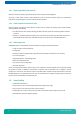
MSM800XEV/XEL / Design Considerations 8.3.3 MSM800XEV V1.1, Top, XPe burn-in test PRO (50% load) 81 t [min] fCPU [MHz] P01 [°C] R11 [°C] R12 [°C] 60 500 51.8 51.6 49.0 www.kontron.
MSM800XEV/XEL / Design Considerations 8.4 Thermal Specifications The temperature is specified by 90°C for the BGA case. The table shows the allowable ambient temperature at various airflows and with different heat sink configurations.
MSM800XEV/XEL / Design Considerations Cooling Option Assembly Example on an MSM800BEV Part-Nr. 807041 Screening E47 (-25°C to 70°C) Heat sink, small (35x37.5x6mm) Available on all MSM800 models Part-Nr. 807042 Screening E48 (-40°C to +85°C) Heat sink, large (79x79.5x8.5mm) Available on MSM800BEV/XEV/XEL models Not possible with MSM800SEV/SEL Part-Nr.
MSM800XEV/XEL / BIOS 9 BIOS 9.1 BIOS History Please consult the BIOS/Driver/Software manual "Geode LX800-LX900" for a detailed BIOS history. 9.2 Core BIOS Download 9.2.1 Before downloading a BIOS Please read through this section carefully and prepare for the download. Make a bootable diskette which includes the following files: Flashrom.com core BIOS xxxxxxxx.yyy Attention: Do not use boot disks created in a Windows operating system. If you do not have an MSDOS 6.
MSM800XEV/XEL / BIOS Attention! Never update a BIOS with a USB memory stick! The system will crash during the download! Only use a USB or a standard floppy. Also, if you have two IDE devices attached to the board (e.g., HDD and CD-ROM), disconnect the CD-ROM before downloading the BIOS. 9.3 ROM-BIOS Sockets An EPROM socket with 8bit wide data access normally contains the board's AT compatible ROM-BIOS. The socket takes a 29F020 EPROM (or equivalent) device.
MSM800XEV/XEL / Previous Product Versions 10 Previous Product Versions 10.1 Board Dimensions – Versions 1.0 / 1.1 / 1.2 86 www.kontron.
MSM800XEV/XEL / Previous Product Versions 10.2 Assembly Views 10.3 Top Side of the MSM800XEV/XEL V1.0 87 www.kontron.
MSM800XEV/XEL / Previous Product Versions 10.4 Bottom Side of the MSM800XEV/XEL V1.0 88 www.kontron.
MSM800XEV/XEL / Previous Product Versions 10.5 Connectors and Jumpers of Previous Product Versions 10.5.1 Description of the Connectors for V1.0 /V1.1 /V1.2 Flat cable 44pin IDE is: All others are: NC: Connector J1 J2 J3 J4 J5 J7 J9 J10 J11 J12 J13 J14 J15 J16 J17 J19 U1 X1 X2 J2 IDT Terminal for Dual Row (2.00mm grid) and 1.00mm flat cable IDT Terminal for Dual Row 0.1" (2.54mm grid) and 1.
MSM800XEV/XEL / Previous Product Versions Pin 1 3 5 7 9 11 13 15 17 19 21 23 25 27 29 31 33 35 37 39 41 43 J4 Pin 1 3 J5 Pin 1 2 3 4 J7 Pin 1 2 3 4 Signal Reset (active low) D7 D6 D5 D4 D3 D2 D1 D0 GND DREQ IOW (active low) IOR (active low) IORDY DACK IRQ14 ADR1 ADR0 CS0 (active low) LED (active low) asp VCC Logic GND Pin 2 4 6 8 10 12 14 16 18 20 22 24 26 28 30 32 34 36 38 40 42 44 JTAG-Port Signal TCK TDI Pin 2 4 Signal TMS TDO USB 1 Connector Signal VCC USB-P0USB-P0+ GND USB 2 Connector Signal
MSM800XEV/XEL / Previous Product Versions Header onboard Pin 1 Pin 2 Pin 3 Pin 4 Pin 5 Pin 6 Pin 7 Pin 8 Pin 9 Pin 10 J10 D-SUB connector Pin 1 Pin 6 Pin 2 Pin 7 Pin 3 Pin 8 Pin 4 Pin 9 Pin 5 Signal DCD DSR RxD RTS TxD CTS DTR RI GND open Serial Port COM2 Header onboard Pin 1 Pin 2 Pin 3 Pin 4 Pin 5 Pin 6 Pin 7 Pin 8 Pin 9 Pin 10 D-SUB connector Pin 1 Pin 6 Pin 2 Pin 7 Pin 3 Pin 8 Pin 4 Pin 9 Pin 5 Signal DCD DSR RxD RTS TxD CTS DTR RI GND open J11 Keyboard PS/2/-Mouse Utility Connector Note: The
MSM800XEV/XEL / Previous Product Versions Front side PS/2 (female) Connector and Adapter Signal Shield DATA GND VCC (+5V) CLK Signal VCC (+5V) DATA GND CLK J12 Mini-DIN PS/2 (6 PC) Shield 1 3 4 5 Mini-DIN PS/2 (6 PC) 4 1 3 5 DIN 41524 (5 PC) Shield 2 4 5 1 Remarks KEYBOARD MOUSE IrDA Connector Pin Signal 1 2 3 4 VCC IRTX IRRX GND BIOS settings: You must enable the UART A of the GeodeLX in the BIOS setup: » F1 Mother board device configuration I/O configuration: » UART port A = enabled » UART mo
MSM800XEV/XEL / Previous Product Versions J13 Printer Port (Centronics) The printer connector provides an interface for 8bit Centronics printers.
MSM800XEV/XEL / Previous Product Versions XJ15 PC/104 BUS Interface Pin 0 1 2 3 4 5 6 7 8 9 10 11 12 13 14 15 16 17 18 19 20 21 22 23 24 25 26 27 28 29 30 31 32 J16 Pin 1 3 5 7 9 11 13 15 17 19 21 23 25 27 29 94 A: B: IOCHCK SD7 SD6 SD5 SD4 SD3 SD2 SD1 SD0 IOCHRDY AEN SA19 SA18 SA17 SA16 SA15 SA14 SA13 SA12 SA11 SA10 SA9 SA8 SA7 SA6 SA5 SA4 SA3 SA2 SA1 SA0 Ground Ground RESET +5Volt IRQ9 NC DRQ2 (-12Volt) 0WS +12Volt Ground NC SMEMW SMEMR SIOW SIOR DACK3 DRQ3 DACK1 DRQ1 REF SYSCLK IRQ7 IRQ6 IRQ5 IRQ4
MSM800XEV/XEL / Previous Product Versions J17 Pin 1 2 3 4 5 6 7 8 9 10 10/100 BASE-T Interface Connector Signal TXTX+ RXRX+ Activity LED BAT Input 3.0-3.6V GND VCC 3.3V Speed LED Link LED At the J17, the LAN interface board including the LAN transformator and the lithium RTC battery (for backup) must be connected. J18 Pin 1 2 3 4 5 6 7 8 9 10 11 12 13 14 15 16 17 18 19 20 21 22 23 24 25 26 27 28 29 30 Notes: PC/104+ BUS Interface A GND/5.0V KEY2 VI/O AD05 C/BE0 GND AD11 AD14 +3.
MSM800XEV/XEL / Previous Product Versions J19 Pin 1 3 5 7 Power Supply Signal GND NC NC GND Pin 2 4 6 8 Signal VCCSUS +5Volt Input Supply (+12V input) PWR_BTN# VCCSUS +5Volt Input Supply VCCSUS = 5Volt Main Supply Input X1 Pin 1 2 3 4 5 6 7 8 9 10 11 12 13 14 15 16 17 18 19 20 21 22 23 24 25 26 27 28 29 30 31 32 33 34 35 36 37 38 39 40 41 42 43 44 96 LCD TFT Interface (flat panel signals) Signal FPM (out) CRT-Vert.Synch Enable BKL (TTL out) CRT-Horiz.Synch VCC 3.
MSM800XEV/XEL / Appendix A: Architecture Information 11 Appendix A: Architecture Information The following sources of information can help you better understand PC architecture. 11.1 Buses 11.1.
MSM800XEV/XEL / Appendix A: Architecture Information 11.3 Ports 11.3.1 RS-232 Serial » EIA232E standard » The EIA-232-E standard specifies the interface between (for example) a modem and a computer so that they can exchange data. The computer can then send data to the modem, which then sends the data over a telephone line. The data that the modem receives from the telephone line can then be sent to the computer. You can search for information about the standard on the Web.
MSM800XEV/XEL / Appendix B: Document Revision History 12 Appendix B: Document Revision History Revision Date Edited by Changes 100 2.Sep.2010 WAS/MEG Changed to new Kontron Corporate Design from DLAG Condensed V1.5C & Detailed V1.7A including title photo; separate manual for each type of MSM800. 99 www.kontron.
MSM800XEV/XEL / Index 13 Index 1 D 10/100 BASE-T interface .................................. 34 A Dimensions and Diagrams .................................66 Document Revision History ................................99 Documentation ........................................... 6, 12 Addressing PCI Devices..................................... 60 DRAM............................................................43 Applications .................................................. 10 Driver Installation ....
MSM800XEV/XEL / Index Interrupt Controllers ....................................... 45 PC104 Bus......................................................56 IrDA ............................................................. 35 PC104/ISA BUS ...............................................40 PC104+ Bus ....................................................58 J PCI/104.........................................................97 Peripherals ....................................................21 JTAG-Port........
MSM800XEV/XEL / Index DMA ................................................................... 15 T EMI / EMC ............................................................ 17 Interrupts............................................................ 15 Mass Storage........................................................ 16 Memory............................................................... 15 Operating Environment .......................................... 17 Peripheral Extensions ............................
MSM800XEV/XEL / Index Corporate Offices Europe, Middle East & Africa Switzerland Kontron AG Oskar-von-Miller-Strasse 1 85386 Eching/Munich Germany Tel.: +49 (0)8165/ 77 777 Fax: +49 (0)8165/ 77 219 Kontron Compact Computers AG Nordstrasse 11/F CH – 4542 Luterbach Switzerland Tel.: +41 (0)32 681 58 00 Fax: +41 (0)32 681 58 01 info@kontron.com infokcc@kontron.com 103 www.kontron.