A Proposal for New Presentations Intelligent Projector AVIO Intelligent Projector iP-40 ER SF AN FR Customer Support Center, Solution Products Division 1-1 KOYATO 2-CHOME SAMUKAWA-MACHI KOZA-GUN KANAGAWA, JAPAN Zip code: 253-0103 Tel: +81-467-73-4426 E-mail: support_ip@avio.co.jp Information on the included manuals URL: http://www.avio.co.jp To customers : Enter the name and date of the store where you purchased this product. This information will be useful when you ask your dealer for repair.
Note: This equipment has been tested and found to comply with the limits for a Class A digital device, pursuant to Part 15 of the FCC Rules. These limits are designed to provide reasonable protection against harmful interference when the equipment is operated in a commercial environment. This equipment generates, uses, and can radiate radio frequency energy and, if not installed and used in accordance with the instruction manual, may cause harmful interference to radio communications.
A Proposal for New Presentations Intelligent Projector User’s Manual iP-40 English Deutsch Français
Warning This is a Class A product. In a domestic environment this product may cause radio interference in which case the user may be required to take adequate measures. Thank you for your purchase of an AVIO product. Please read this manual carefully in order to use the projector properly. After reading this, please keep it in a safe place together with the warranty sheet. Features of the iP-40 • Very versatile six-in-one projector. A projector for the multimedia age. 1.
Safety Precautions WARNING ● If a fault occurs: • If you detect smoke, or a strange smell or sound, immediately disconnect the power cable. It is dangerous to continue using the projector after a fault occurs. Return the projector to the dealer where it was purchased for repair. ● Avoid placing the projector near dangerous substances. • Make sure that no metallic or flammable material can get into the projector through the air vents.
Safety Precautions CAUTION • Installation • Avoid installing the projector in places where it may be exposed to: - On tables, etc., that are vulnerable to heat. - Strong vibrations - Soot or steam - Direct sunlight or near a heater (35°C/95°F or higher) - High humidity or dust - Extreme cold (0°C/32°F or lower) - Strong magnetic or electric field generated from a nearby appliance - Wobbling on an unstable surface • Do not block the air vents. • Do not block the air vents with cloth or an object.
Safety Precautions • Lamp implosion • A DC type Super High pressure lamp is used in this projector and it is rare for the lamp to explode during use. The unit is also designed to forcibly turn off the lamp because there is a high possibility that the lamp will break if it is used beyond the lamp usage of 2000 hours (Refer to pages E-43 and E-45). Note the following things • A sound occurs because the internal pressure of the Super High pressure lamp gets extremely high.
Table of Contents Safety Precautions.................................................. E-3 A Check of the Supplied Items and the Names of the Parts............................... E-7 Supplied Parts Check................................................ E-7 Names and Functions of the Parts (Projector).......... E-8 Names and Functions of the Parts (Input Connectors) ........... E-10 Names and Functions of the Parts (Operation Panel) ............ E-11 Names and Functions of the Parts (Remote Control) .........
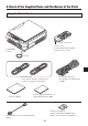
A Check of the Supplied Items and the Names of the Parts Supplied Parts Check BY ND ER TA V /S /CO MP O N MP T E LA P IN UT RO ON TI TA TR FR SF AN ZE EE ER OF F FR Z EE E/C AP RE TU Please check that the supplied parts are included. Pull out the sheet before use. Remote control Coin-type lithium battery: CR2025 (Inside the remote control) iP-40SE/40BE Projector Lens cap PC connection cable (2 m)* * No USB cable is included with the iP-40BE.
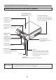
A Check of the Supplied Items and the Names of the Parts Names and Functions of the Parts (Projector) Focus adjustment ring Turn this to adjust the focus. See Page E-22. Document cover The document or printed material to be read is placed under this cover. See Page E-34. Air intake vent (Air filter) Air is drawn into the projector from here. There is an air filter to prevent dust from entering the inside of the projector. See Page E-50.
A Check of the Supplied Items and the Names of the Parts Document reading area The document or printed material that you wish to project in the OHP mode is placed here. See Page E-34. BY ND ER TA V /S /CO MP O N MP T E LA Input connector panel The connectors for the personal computer, video, and other connections are located here. See Page E-10.
A Check of the Supplied Items and the Names of the Parts Names and Functions of the Parts (Input Connectors) TEST 1 RGB V 2 3 L R 4 1. Test (maintenance) connector This special connector is used at the time of maintenance and factory tests. It cannot be used for other connections. 2.
A Check of the Supplied Items and the Names of the Parts Names and Functions of the Parts (Operation Panel) INPUT ON/STANDBY LAMP/COVER TEMP 1 2 ROTATION FREEZE OFF FREEZE/CAPTURE TRANSFER 3 4 5 6 1. ON/STANDBY LED Lit red during standby and lit green when the projection lamp is on. See Page E-21. 2. LAMP/COVER LED Lit green during projection. Lit red when the air filter or lamp unit cover is not in place.
A Check of the Supplied Items and the Names of the Parts Names and Functions of the Parts (Remote Control) 6. MENU Button Switches on or off the display of the menu screen. See Page E-36. 1 2 7. SCROLL Buttons Sets the selection of the item or the adjustment value at the menu screen. Moves the zoom position during a zoom display. Moves the pointer when the pointer is being displayed. See Pages E-24, 25, 28 and 33. 3 4 5 6 7 9 8.
A Check of the Supplied Items and the Names of the Parts Operation of the Remote Control • Please use the remote control within a range of about 7 m from the remote control IR sensor of the projector (located at both the front and rear) and within an angle of 10 degrees to the left and 10 degrees to the right. Note that this distance may be shorter depending on battery consumption.
Procedure Up to Projection 1 Consideration of placement location and screen size Determine the screen and projector setup location. Set the projector on a strong and stable, level platform. See Page E-15 for information about the projection distance and screen size. 2 Connections with input equipment Connect your personal computer/video equipment.
Projection Distance and Screen Size Please use the following diagrams to determine the screen display size and the type of screen required for any given projector location. Projection distances that will be in focus will be 1.3 m (4.3 feet) to 11 m (36 feet) from the front of the lens. Please arrange the setup within this range. (inch) 350 300 300 250 Wide 200 200 150 150 100 100 50 40 150 Tele 100 80 60 200 80 60 40 30 0 0.0 0.0 2.0 6.6 4.0 13.1 6.0 19.7 8.0 26.2 10.0 32.8 12.
Connections with the Personal Computer CAUTION Connection Precautions • To protect this projector and the equipment to be connected, switch off the power of each unit before making connections. • Please read the various equipment instruction manuals for information about the connection of the equipment and the method of use. • When connection is made with a notebook computer and the image is displayed on the LCD screen of the notebook computer, a proper display might not be obtained on projection screen.
Connections with the Personal Computer Connecting Macintosh Computers • When the monitor output is set to the VGA port (mini D-SUB 15-pin), mount the PC connection cable included with the main unit. • An optional Apple video adapter cable is required when the monitor output is a video port or DVI port. • Please do not make a USB connection because iP Viewer* does not support the Macintosh. * The iP Viewer function is only available on the iP-40SE.
Connections with the Personal Computer When the Image of the Personal Computer Screen Is Not Projected Please check the matters described below when the image of the personal computer is not projected or when there is projection but the image is not correct. ● The image is not projected When the external output signal from the personal computer is not input to the iP-40, "No computer signal being input" is displayed on the display screen of the iP-40. Should this occur, please check the following matters.
Connections with the Personal Computer Table of Supported Input Signals Signals indicated with a “Yes” are supported. Note that depending on the model of personal computer, please perform the screen adjustment of the "Image adjustment" → "Sync adjustment" menu if flickering or bleeding appear on the projection screen. → See Page E-42 Signal Name NTSC RGB PAL/SECAM RGB Resolution (Horizontal Vertical) - Horizontal Frequency (KHz) 15.7 Vertical Frequency (Hz) 60 Supported No - - 15.
Connections with Video Equipment The video of a video tape deck or DVD player is projected onto a large screen. (*) TEST RGB V L R AUDIO MEMORY USB iP-40 Projector side connector panel D terminal/ RGB conversion cable (Option: Model name IPC-D/VGA) To the video output connector To the audio output connectors Video deck DVD player * The USB terminal and SD memory card can be used only for iP-40SE. NOTE: • When a video signal have a lot of noise, the image may be displayed in monochrome.
Connection of the Power Cable and On/Off Switching Switch On the Power 1 Connect the power cable The projector will enter the standby mode and the ON/STANDBY LED will light in red. BY ND R TA OVE P N/S C M O MP/ TE LA INPUT T PU IN ON/STANDBY LAMP/COVER TEMP TI TA RO ON R OFF SFE AN ZE EE FR TR FR EE TU AP /C ZE RE TE TEST ST RG RG BB V S L V R L AU DI OR MEM AU OR DI OY 電源 接続コー ドは をし をしドは 必ず てく てく必ず ださ アー ださアー い。 い。スス US US B AC B IN To wall outlet.
Adjustment of the Projection Image Adjusting the Projection Image Adjust the projection image to the screen. • When the image is shifted to the left or right, move the projector horizontally. (Align the center of the screen with the center of the projector lens.) • When the image is shifted up or down, use the tilt foot to adjust the projector vertically. • When the image is slanted, turn the left or right tilt foot to adjust.
Regular Operation This section describes the use of direct operation using the projector and remote control buttons. Please see the items on Page E-32 "Menu Operation Method" and Page E-39 "Menu Description" for information about operation using the menu. Select the Input When the projector’s power is turned on, one of the input selection icons ([OHP, PC or VIDEO] or [OHP, VIDEO (Component) or VIDEO]) is displayed.
Regular Operation To view the portion that has been cut off Operation with the Projector Scrolling is not possible from the main unit’s control panel. Operation with the Remote Control Press the SCROLL (▲▼) buttons and scroll the projection image up or down. A B C • Pressing the ZOOM (–) button permits display of a large portion within the reading range of the vertical display. The undisplayed portion can be displayed with the SCROLL (▲▼) buttons.
Regular Operation Moving the Screen Movement is possible in 4 directions (up, down, left, and right). Operation with the Projector Scrolling is not possible from the main unit’s control panel. Operation with the Remote Control Press the SCROLL (▲▼◀▶) buttons. Adjusting the Brightness To change the brightness, perform a manual adjustment using the method described below. Operation with the Projector The brightness cannot be adjusted from the main unit’s control panel.
Regular Operation Capturing the Projection Image At OHP input ON/STANDBY LAMP/COVER TEMP Effective Only with OHP Input INPUT Pressing still freeze/capture button automatically stores the OHP information into the incorporated memory as the OHP history image. The image in the incorporated memory is erased by turning off the power. ROTATION FREEZE OFF FREEZE/CAPTURE TRANSFER / Still Image Display Operation with the Projector] Press the still freeze/capture button.
Regular Operation During PC/VIDEO Input Each time the FREEZE/CAPTURE button is pressed, the currently projected image will be frozen (in a fixed display). NOTE: • The FREEZE LED is lit green during the still image display. • A press of the FREEZE/CAPTURE button while a moving image is projected will result in a still image display at the existing zoom magnification and position.
Regular Operation Making presentation using the incorporated memory or SD memory card The history image saved in the incorporated memory or SD memory card * and the presentation image created with iP Viewer are projected with the projector. Making presentation using the image in the incorporated memory. 1 When the SD memory card has been inserted in the main memory card, remove it * The SD memory card takes precedence on the projector.
Regular Operation 4 Operation with the Remote Control Full-screen projection Press the Remote Control’s set/pointer button. The reduced image at the cursor position is projected on the full screen of the projector. 1 2 3 4 5 6 7 8 9 13 10 14 11 15 12 16 NOTE: • The image that was changed over and saved in the vertical direction is projected vertically even when it is displayed laterally in the reduced-size screen. • This operation is available only by the Remote control.
Regular Operation Using the SD memory card image to make presentation * * Our optional item (model: AV-SDSDC1GB) is guaranteed to operate. The other SD memory cards are not guaranteed to operate Depending on the type of the SD memory card, the processing speed may become slower. The SDHC standard SD memory card and high-speed SD memory card (class6) are not supported. 1 Prepare the material Set the SD memory card in the main unit.
Regular Operation 5 Operation with the Remote Control Choosing a file Press the remote control’s scroll ▲▼◀▶ button and set the cursor to the reduced image you want to project. When the number of the reduced size screen images exceeds 16, press the scroll ▼ button to display the 17th reduced screen image. Cursor 1 2 3 4 5 6 7 8 9 13 10 14 11 15 12 16 NOTE: The image file that cannot be played back with the unit is not displayed.
Regular Operation Transferring Captured Images * When connection is made with a USB ON/STANDBY LAMP/COVER cable, history images can be transferred to TEMP the personal computer. INPUT Operation with the Projector When the input is set to PC/component video: Press the TRANSFER button. When input set to OHP: Long-press the TRANSFER button. ROTATION FREEZE OFF FREEZE/CAPTURE TRANSFER Operation with the Remote Control When the input is set to PC/component video: Press the ROTATION button.
Regular Operation Displaying the Pointer This operation displays the pointer in the currently projected image. Operation with the Projector The ability to turn on and turn off the pointer is not available from the operation panel of the projector. Operation with the Remote Control Press the SET/POINTER button. One more press of the SET/POINTER button while the pointer is displayed will turn off the pointer display.
Method of OHP Operation Attaching the Document Cover BY ND R TA VE P /S CO M ON MP/ TE LA The mounting orientation of the document cover can be changed to the opposite direction in accordance with the circumstances circumstances. T PU IN TA RO TI ON OFF ER ZE SF EE FR AN TR EE FR RE TU AP /C ZE TE TEST ST RG RG BB V S L V R L AU DI OR ME AU MO DIRY O 電源 接続コー をしドは てく必ず ださアー い。ス US US B AC B IN NOTE: When removing the document cover, lift the cover by both hands and remove it.
Menu Configuration The adjustment/setting items and content will differ depending on the input selection and the permitted information will be displayed on the menu for that input mode. Pointer • Screen Image adjustment Pointer • Screen Pointer • Screen History menu Settings Image adjustment Pointer size No.
Menu Operation Method Names and Functions of the Buttons Used in Menu Operation SCROLL ▲▼◀▶ Buttons Used in the selection of menu names and item names, and to set and adjust item contents. SET/POINTER Button Used to finalize a setting after making the setting or adjustment. MENU Button Used to display a menu and to close a menu. Names and Functions of the Menu Parts Menu tab Switches to the various menus when selected. Cursor (Light blue) Selects the item that you would like to set or adjust.
Menu Operation Method Method of Menu Operation This section describes the actual operation method. Adjustment of [Keystone (Manual)] using the remote control is provided as an example. 1 Press the MENU button and display the menu 2 Select [Settings] with the SCROLL ◀▶ buttons Each press of the SCROLL ▶ button switches the menu one step in the sequence of [Pointer • Screen] → [Image adjustment] → [Settings], and each press of the SCROLL ◀ button causes a return in the opposite direction.
Menu Operation Method 4 Press the POINTER/SET Button Switches the menu to the sub menu (i.e., the Keystone adjustment menu). 5 Make the adjustment with the SCROLL ◀▶ buttons while checking the projection image SCROLL ◀ button: SCROLL ▶ button: 6 Press the MENU button and close the menu This completes the [Keystone (Manual)] adjustment. E-38 Each press causes the numerical value to decrease. (The lower portion of the projection image becomes narrower.
Menu Description Pointer • Screen This selects the shape, color, and size of the pointer. During OHP input Pointer shape...................Selects the shape of the pointer from 2 types. Pointer color.....................Selects the color of the pointer from amongst 3 types (i.e., red, white, and blue). Pointer size.......................The size of the pointer can be changed in 3 levels. Mute mode.......................Sets the image that will be displayed at the time of screen deletion.
Menu Description History menu OHP input only No. sheets on thumbnail display.............................Select the number of thumbnail images to be displayed simultaneously on one screen. 4 sheets: Four thumbnail images are displayed at once. 16 sheets: 16 thumbnail images are displayed at once. (When displaying the SD memory card image, the 16-image display is fixed.) When a list of history images is displayed Erase entire history..........A confirmation message appears.
Menu Description Image adjustment This performs the settings and adjustments related to the projected image. During OHP input When OHP input has been selected. Red (Red color adjustment).........Adjusts the deepness of the red color in the range of -50 to 50. Blue (Blue color adjustment).........Adjusts the deepness of the blue color in the range of -50 to 50. Sub menu: Color mode Standard...........................The contrast is strong and the image is crisp. Presentation.....................
Menu Description Sub menu: Sync adjustment Clock................................Adjusts the horizontal size of the projected image in the range of -50 to 50. Phase...............................Adjusts the noise/flickering of the projected image in the range of -50 to 50. Horizontal.........................Adjusts the horizontal position of the projected image in the range of -50 to 50. Vertical.............................
Menu Description Settings This performs settings related to the projector unit or while the projector is in use. Lamp usage time..............Displays the usage time of the lamp. "Replacement of the Lamp Unit" → See Page E-47 Input signal.......................The name of the currently selected input is displayed. Setting Items Keystone..........................Performs keystone correction of the projection image.
Menu Description Projection mode...............Selects the projection system of the projector from between Front (front projection) and Rear (rear projection). Economy mode................ON (Economy mode): The brightness of the lamp will be approximately 80%. The lamp service life will be extended. OFF (High brightness mode): The brightness of the lamp will be 100%. There will be a bright screen. Auto power off..................
Maintenance Fault Protection The projector is equipped with a built-in protection circuit to prevent fire and breakdown due to faults. When the LAMP/COVER LED lights in red Measures to be taken 1. Disconnect the power plug from the outlet. 2. Properly install the lamp unit cover. See "Replacement of the Lamp Unit" on Page E-47. When the TEMP LED flashes or lights steadily Measures to be taken 1. Disconnect the power plug from the outlet. 2.
Maintenance When the power has failed (When all the LED go off with the power ON) Measures to be taken 1. Disconnect the power plug from the outlet. 2. Check the following matters and perform the countermeasure properly. Is the ambient temperature in excess of 35°C (95°F)? Please use the projector in an operation ambient temperature of 0°C (32°F) to 35°C (95°F). Are the ventilation vents blocked? Rearrange the setup location of the projector and separate the projector from surrounding objects.
Maintenance Replacement of the Lamp Unit The projection lamp used on this projector should be replaced after about the number of hours indicated below (or sooner, depending on the usage conditions). When the usage time exceeds 2000 hours*, the possibility for explosion increases, so the lamp is forcibly shut off. When the usage time exceeds 1900 hou rs, replace the lamp unit (sold separately) before the usage time reaches 2000 hours.
Maintenance Lamp Unit Replacement Procedure To prevent burns, wait one hour or longer after the lamp has been switched off before performing the following procedure. 1 Remove the lamp unit cover Using a minus screwdriver, loosen the screws of the lamp unit cover, pull in the direction of the arrow, and remove the cover. 2 Loosen the mounting screws of the lamp unit Using a minus screwdriver, loosen the 2 screws of the lamp unit.
Maintenance 5 Reset the lamp usage time Please perform the operation indicated below in the standby mode (*). Operation with the Projector Press the INPUT, PORTRAIT, FREEZE OFF and FREEZE/CAPTURE buttons simultaneously, then press the input selector and still picture buttons simultaneously. Operation with the Remote Control Resetting of the lamp usage time cannot be performed with the remote control. The LAMP/COVER LED will flash green following this and projection will start.
Maintenance Cleaning the Air Filter The air filter is an important part that prevents the intrusion of dust onto the optical parts and other parts inside the projector. When the air filter becomes blocked, the internal temperature will rise and the rotation of the fan will also increase leading to a reduction of the service life or causing breakdown. In view of this, the air filter should be cleaned regularly (about once a month, when the projector is used 4 hours per day).
Troubleshooting When you think the projector may be out of order, please first check the following matters before requesting repair. Symptom Please check this Reference page Power does not come on • Is the power cable connected? E-21 Projection lamp does not light • • • Is the lamp burned out? Is the lamp unit cover installed? Is the internal temperature high? If so, the lamp will not light to protect the projector from damage.
Repair Service Repair Service Procedure • Before asking for repair service, check the Troubleshooting section on page E-51 once more. If this check confirms a problem, contact the dealer where you bought the product. • When asking for repair service, provide your dealer with the following information: Description of the problem (as many details as possible) Date of purchase Your Name Your Address Telephone number Product name and model No.
Specifications Model Name iP-40SE/iP-40BE Type Single-plate DLP ® color wheel color separation type Main Part Specification DLP ® chip Size 0.7” DLP ® chip x 1, aspect ratio 4:3 Number of Pixels 786,432 pixels (1,024 x 768 dots) Projection Lens F2.6 to 2.9, f = 25.8 to 30.0 mm, zoom ratio 1.16 Optical Source 200W Super High-pressure Mercury Lamp Image Size 33-300 inches diagonal (projection distance 1.3 to 11.
Viewing the iP Viewer’s Operating Instructions The Intelligent Projector includes a presentation application called “iP Viewer” offering convenient annotation and data storage functions. Use the procedure below to read the operating instructions and be sure to use the projector properly. The USB device driver is loaded in the projector’s memory. The projector must be connected to the computer using a USB cable in order to install the USB device driver* on the computer.
Power cable for Singapore E-55