Notice The information in this guide is subject to change without notice. Compaq Computer Corporation shall not be liable for technical or editorial errors or omissions contained herein; nor for incidental or consequential damages resulting from the furnishing, performance, or use of this material. This guide contains information protected by copyright. No part of this guide may be photocopied or reproduced in any form without prior written consent from Compaq Computer Corporation.
Preface USING THIS GUIDE This Maintenance And Service Guide is a troubleshooting reference for servicing the Compaq LTE Elite Family of Personal Computers, the Compaq SmartStation, the Compaq MiniStation/EN, and the Compaq MiniStation/TR.
>>>>>>>>>>>>>>>>>>>>>>>>>>>>>>>>>>>>><<<<<<<<<<<<<<<<<<<<<<<<<<<<<<<<<<<<<< IMPORTANT: Text set off in this manner presents clarifying information or specific instructions. NOTE: Text set off in this manner presents commentary, sidelights, or interesting points of information. TECHNICIAN NOTES >>>>>>>>>>>>>>>>>>>>>>>>>>>>>>>>> WARNING <<<<<<<<<<<<<<<<<<<<<<<<<<<<<<<<< Only authorized technicians trained by Compaq Computer Corporation should attempt to repair this equipment.
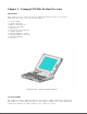
Chapter 1 - Compaq LTE Elite Product Overview Introduction This chapter is an overview of the Compaq LTE Elite Family of Personal Computers and covers the following topics: o o o o o o o o o o o Serial number System overview Models and features Controls and LEDs Connectors Functional descriptions Docking options Running Computer Setup Reprogrammable flash ROM Power Management Security 1.
1.
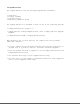
Computer power is supplied through one of the following sources: o An internal battery pack o The computer's internal AC adapter when connected to the power cord (Figure 1-2) o The computer's internal AC adapter when docked in a convenience base o The 198-pin external options connector when docked in an expansion base (provides DC power) o Automobile Adapter (provides DC power)
1.3 Models And Features Models Table 1-1 lists the Compaq LTE Elite models and model-specific features. Table 1-1. Compaq LTE Elite Computer Models =========================================================================== Internal Model Display Processor Cache RAM Hard Drive =========================================================================== 4/75CX 9.5" Color TFT 486 DX4/75 MHz 16 KB 8 MB 340 or 510 MB 4/50CX 9.5" Color TFT 486 DX2/50 MHz 8 KB 8 MB 340 MB 4/40CX 8.
o Internal AC adapter o Upgradeable SL Enhanced Intel486 microprocessors o User upgradeable display with integrated trackball o Local bus graphics and graphics accelerator with 1024 x 768 external video support o Simultaneous display capability o Removable 2.5-inch hard drive o Reprogrammable flash ROM (Section 1.9) o 4 MB system RAM expandable to 20 MBs or 8 MB system RAM expandable to 24 MBs. The following memory expansion boards are available (Section 1.6): - 4 MB - 8 MB - 16 MB o 1.
o The following preinstalled software: - MS-DOS and Microsoft Windows - TabWorks utility (alternative to Program Manager) - Computer Setup, Computer Checkup, Power Management, and Security Management utilities - Automatic PCMCIA configuration utilities for MS-DOS and Windows - Windows-based online documentation - Plug and Play BIOS - MS-DOS- and Windows-based shutdown capability (for closing out applications and turning off computer) - Microsoft Video for Windows Runtime Version - Adaptec 6360 SCSI dri
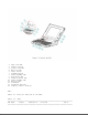
1. 2. 3. 4. 5. 6. 7. 8. 9. 10. 11. 12. 13. 14. Caps lock LED Display switch Scroll lock LED Num lock LED Power switch Standby button Power/standby LED Hard drive LED Diskette drive LED Power/standby LED Battery LED Trackball Trackball buttons Display control slide(s) LEDs Table 1-2 lists the function of the LEDs. Table 1-2.
Power/ standby On Flashing Power on Standby LED on top of unit Green (active when display is open). Identical LED on front of unit (active when display is closed).
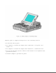
1. 2. 3. 4. 5. 6. 7. 8. 9. AC power Automobile Adapter Serial 198-pin external options Keyboard/mouse Parallel External monitor Numeric keypad PCMCIA AC Power Connector When the computer is docked in the convenience base and the convenience base is turned on, AC power is applied to the computer's AC power connector. (The 198-pin connector carries all other signals between the two units.) Automobile Adapter Connector The computer has an automobile adapter connector that accepts an 18.5 volt, 1.
NOTE: The automobile adapter converts 12 volts DC from the automobile to 18.5 volts DC for use by the computer. >>>>>>>>>>>>>>>>>>>>>>>>>>>>>>>>> CAUTION <<<<<<<<<<<<<<<<<<<<<<<<<<<<<<<<< The computer has an access door for the automobile adapter connector that is designed to allow only one type of power input (AC or DC) to be connected at a time (Figure 1-5). Do not attempt to defeat this protective feature of the door or internal damage to the computer may result.
Keyboard/Mouse Connector The keyboard/mouse connector can be connected to a PS/2 mouse or an external enhanced keyboard. Connecting the mouse/keyboard connector to a mouse disables the integrated trackball, while connecting the mouse/keyboard connector to an external keyboard disables the internal keyboard. Parallel Connector The parallel connector supports the parallel interface which meets EPP 1.9 specifications.
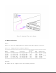
The system board (Figure 1-6) provides the following: o Connector for removable hard drive [1] o PCMCIA connector [2] (refer to "PCMCIA Slot") o Board-to-board connection to the following devices: - Power interface board (PIB) [3] - Processor board [4] - Memory expansion board (on underside of system board) o Cable connection to the following devices: - Internal AC power supply board [5] - Fan [6] - Internal keyboard [7] - Display [8] - Diskette drive [9] - LED cable assembly for front-mounted LEDs (on un
o Battery charging circuitry and battery contacts [10] for battery pack o External input/output (I/O) connectors (Figure 1-4) o DC-to-DC power supply (refer to "DC-to-DC Power Supply" in this section) o 256 Kbyte flashable shared system ROM and keyboard ROM o 4 or 8 MB base RAM (depending on the model) o System controller, which provides the following: - Interface to the processor board for memory management (including memory refresh) - Two DMA controllers - Two interrupt controllers - Clock generator - Pr
voltage input comes from one of the following sources: o o o o o Internal AC power supply Battery pack Automobile adapter 198-pin external options connector (from expansion base) Auxiliary battery To replace the DC-to-DC power supply, the system board must be replaced. Processor Board The SL Enhanced Intel486 processor has an integrated coprocessor and is upgradeable by replacing the processor board (Figure 1-7). The system automatically adjusts to the new configuration.
NOTE: The 75 MHz processor is also available as an upgrade option. Temperature Sensors The primary temperature sensor is located on the processor board and the secondary temperature sensor is located on the system board. These sensors turn the fan on when the system approaches maximum reliable operating temperatures.
o o o o o o Numeric keypad connector Speaker and speaker amplifier Power switch Standby button Display switch The following LEDs: - Power/standby - Scroll lock - Caps lock - Num lock Refer to Section 1.4 for more information on the controls and LEDs listed above. Memory Expansion Board The 4 or 8 MB base RAM memory (depending on the model) may be increased by adding an optional memory expansion board (Figure 1-9). The memory expansion board plugs directly into the back side of the system board (Section 4.
o 4 MB o 8 MB o 16 MB NOTE: Some early memory expansion boards for the Concerto Family of Personal Computers (option kit numbers 144790-001 and 144790-002) operate at 80 ns and do not function properly when installed in the Compaq LTE Elite Family of Personal Computers, which operate at 70 ns. Use only Compaq LTE Elite memory expansion boards (Table 3-2). Refer to the table in Section 5.3 for a list of total RAM memory based on available system memory and memory obtained from the expansion board.
The internal fan (Figure 1-11) draws in fresh air through vent holes in the PCMCIA compartment door, then exhausts it out the back of the computer. The fan operates on 5 volts and is controlled by temperature sensors located near the internal power supply and the processor board. The fan is designed to turn on automatically when the system approaches maximum reliable operating temperatures (refer to "Temperature Sensors" in this section).
The removable internal nickel metal hydride (NiMH) battery pack connects to the computer through a set of battery contacts mounted on the system board. Battery charging functions are controlled by the DC-to-DC converter on the system board. The battery pack contains RAM memory that saves the last recorded battery operating time and battery fuel gauge values.
memory for a one-minute period during Standby to allow a battery pack to be replaced. The auxiliary battery has a nickel cadmium cell that supplies 7.2 volts for 50 mAmp hours. The auxiliary battery recharges when the computer is on while connected to an external power source or the battery pack. It takes approximately 10 hours to recharge a fully discharged auxiliary battery using AC power and approximately 20 hours to recharge it using the battery pack.
The 2.5-inch hard drive (Figure 1-13) is user-removable from the front of the computer (Section 4.12). The hard drive release button allows the drive to be removed without disassembling the computer. A connector on the hard drive enclosure mates to a connector on the system board. NOTE: The hard drive may have either a metal handle (Figure 1-13) or a plastic pull tab that is attached directly to the hard drive enclosure.
is already created and the diagnostics utilities are already installed. IMPORTANT: The hard drive must be handled with care. listed in Section 4.12. Refer to the cautions Display Assembly The display assembly (Figure 1-14) is connected to the system unit by clutches, a display cable and a ground cable. The display assembly includes an integrated trackball board and an inverter board. The color and black-and-white TFT display assemblies have an externally adjustable brightness control slide [1].
Refer to Section 5.4 for display specifications. NOTE: A certain number of pixels in the display panel are allowed to be nonfunctional due to limitations in LCD technology. PCMCIA Slot The PCMCIA connector is mounted to the system board. The connector is accessible through the PCMCIA slot [1], (Figure 1-15), which is covered by a PCMCIA compartment door.
NOTE: PCMCIA stands for Personal Computer Memory Card International Association. PCMCIA standards continue to change. Many cards on the market do not comply with the PCMCIA specifications and, therefore, do not function properly in the computer. To assist users in selecting compatible PCMCIA devices, Compaq provides a list of third-party cards that have been tested in Compaq products. To ensure compatibility, select a Compaq PCMCIA modem or other vendor cards on the tested list.
Run Computer Setup for the following situations: o To configure options o To update alarm, time, date, or password information NOTE: Alarm, time, and date information can be lost if the computer is unused for approximately 60 days without charging the internal battery pack or without AC power being connected (refer to "Auxiliary Battery" in Section 1.6). If this information is lost, run Computer Setup to restore it. IMPORTANT: Use AC power during Computer Setup procedures.
and when the system is idle. This function is transparent to the user. APM also provides occasional screen messages about the battery while in the Windows environment (for example, low power condition). Power Management Settings You can select power conservation settings through Computer Setup, Power Management, or by pressing the Fn + F7 hotkeys to maximize power for specific requirements. These settings control the power conservation rate and the timeout values for various system components.
Standby is a power conservation mode for battery or AC power operation during which most of the components (e.g, hard drive, processor, display) shut down. The computer initiates Standby under the following conditions: o When the user presses the standby button [1] (Figure 1-17). o After a timeout occurs. o When the battery pack voltage reaches a low level (if this option is preselected).
Hibernation Hibernation is a power conservation mode that performs the following functions: o Locks the keyboard and clears the screen. o Saves all current information in memory and the place in the application to the hard drive. o Turns the computer off. Hibernation is preenabled on the computer and the Hibernation file is preinstalled on the hard drive. The Hibernation file is slightly larger than the total RAM memory of the computer (system memory and memory expansion board).
1.11 Security The computer has the following security features: o Power-on password and setup password. o The ability to disable certain components, such as the keyboard, diskette drive, display, PCMCIA slot, parallel connector, and serial connector, to prevent unauthorized access. o Provision for an optional cable lock (Figure 1-18) to lock the computer to an immovable object. NOTE: For procedures to clear the power-on password, refer to "Clearing the Power-On Password" in Section 2.1.
Chapter 2 - Compaq LTE Elite Troubleshooting Introduction This chapter covers troubleshooting information for the computer. The basic steps in troubleshooting include: 1. Following the preliminary steps listed in Section 2.1. 2. Running the Power-On Self-Test (POST) as described in Section 2.2. 3. Running Computer Checkup (TEST) as described in Section 2.3. 4. Following the recommended actions described in the diagnostic tables in Section 2.
5. Disconnect any external devices that you do not want to test. (Do not disconnect the printer if you want to test it or use it to log error messages.) NOTE: If a problem only occurs when an external device is connected to the computer, the problem may be with the external device or its cable. Verify this by running POST with and without the external device connected. 6. Install loopback plugs in the serial and parallel connectors if you would like to test these ports (Table 3-13). 7.
password-clearing position [2]). Refer to Figure 2-1. 6. Move the jumper from the normal "1-2" position [1] to the "2-3" position [2] (Figure 2-1). 7. Insert the battery pack. IMPORTANT: Ensure that the battery pack is charged since a low battery condition could initiate Standby and interrupt the procedure. 8. Turn on the computer. The ROM clears the power-on password during POST. 9. After POST finishes, turn off the computer. 10. Remove the battery pack. 11.
12. Insert the battery pack. 13. Turn on the computer to verify that the power-on password has been cleared. If it has not been cleared, remove the battery pack and then repeat steps 6 through 13. If the password is still not cleared, replace the system board (Section 4.17). 14. Replace the keyboard. 15. Replace the keyboard cover. 16. Reconnect the power cord to the external outlet. 17. Run Computer Setup (Section 1.8) to reconfigure the system and reset the power-on and setup passwords. 2.
If POST does not detect any errors, the computer beeps once or twice to indicate that POST has run successfully and starts (boots) from the hard drive (or from a bootable diskette if one is installed in the diskette drive). If POST detects errors, the errors are indicated by screen and/or audible messages. Refer to "Power-On Self-Test (POST) Error Messages" in this section for a list of POST error messages, probable causes, and recommended actions.
Increase Detected memory incorrect. apply to both 164 error codes: 1. Autosetup will correct. 2. Verify that memory board is installed correctly. 3. Replace memory board. 4. Replace system board. -----------------------------------------------164 - Memory 2 Short Configuration Decrease memory incorrect. Detected --------------------------------------------------------------------------168 - CMOS None Auxiliary battery 1. Recharge auxiliary Checksum charge is low. battery.
--------------------------------------------------------------------------205 - Memory None Cache memory error. 1. Run Computer Checkup. Error 2. Replace the processor board. --------------------------------------------------------------------------207 - Invalid None Memory module Verify placement of Memory installed memory. Configuration incorrectly. Module --------------------------------------------------------------------------209 - NCA RAM None RAM Failure. Run Computer Checkup.
4. Replace the system board. --------------------------------------------------------------------------602 - Diskette None Diskette in drive A 1. Replace the diskette. Boot not bootable. 2. Replace the diskette drive. 3. Replace the system board. --------------------------------------------------------------------------605 - Diskette 2 Short Mismatch in drive Run Computer Setup. Drive Error type.
Failure 2. Replace the system board. --------------------------------------------------------------------------1150 - COM Port Two ports are Run Computer Setup. Configuration configured in the Error same address. --------------------------------------------------------------------------1151 - COM Port 2 Short Both external and Run Computer Setup. 1 Address internal serial Assignment ports are assigned Conflict to COM1.
---------------------------------------------Defective system If the drive in the board in expansion expansion base is base. designated as secondary, replace the system board in the expansion base. ---------------------------------------------Defective system If the drive in the board in computer. computer is designated as secondary, replace the system board in the computer.
The Configuration and Diagnostics menu is displayed. 4. Select Computer Checkup (TEST) from the Configuration and Diagnostics menu. The Computer Checkup options menu is displayed. 5. Select View Device List. A list of the installed hardware devices is displayed. NOTE: Computer Checkup may not detect non-Compaq devices. 6. Verify that Computer Checkup correctly detected the installed devices. If the list is correct, select OK. The Computer Checkup option menu is displayed again.
12. Rerun POST and Computer Checkup, completing the recommended actions in the order given until the problem is solved and no error messages occur. Computer Checkup (TEST) Error Codes Computer Checkup (TEST) error codes occur if the system recognizes a problem while running Computer Checkup. These error codes help identify possible defective assemblies. Tables 2-2 through 2-13 list Computer Checkup error codes, a description of the error condition, and the recommended action for resolving the condition.
failed. --------------------------------------------------------------------------112 - xx Speed test slow mode Replace the system board. out of range. --------------------------------------------------------------------------113 - 01 Protected mode test Replace the system board. failed. --------------------------------------------------------------------------114 - 01 Speaker test failed. 1. Check system configuration to verify that speaker is enabled. 2. Check speaker volume level on popup window. 3.
8042 self-test failed. If disconnected, turn off the computer and connect the keyboard. 2. Replace the keyboard. 3. Replace the system board. --------------------------------------------------------------------------302 - xx Keyboard long test 1. Check the keyboard connection. failed. If disconnected, turn off the computer and connect the keyboard. 2. Replace the keyboard. 3. Replace the system board. --------------------------------------------------------------------------303 - xx Keyboard LED test, 1.
604 - xx Diskette random seek test failed. 605 - xx Diskette ID media failed. 606 - xx Diskette speed test failed. 607 - xx Diskette wrap test failed. 608 - xx Diskette write protect test failed. 609 - xx Diskette reset controller test failed. 610 - xx Diskette change line test failed. 697 - xx Diskette type error. 698 - xx Diskette drive speed not within limits. --------------------------------------------------------------------------699 - xx Diskette drive/media 1. Replace media.
Table 2-9. Hard Drive Computer Checkup Error Codes =========================================================================== Error Code Description Recommended Action =========================================================================== 1700 - xx Hard ID drive types The following steps apply to test failed. 1700 - xx through 1799 - xx error codes: 1701 - xx Hard drive format test failed. 1. Run Computer Setup and verify drive type. 1702 - xx Hard drive read test 2. Reseat the hard drive. failed. 3.
Table 2-10. Tape Drive Computer Checkup Error Codes =========================================================================== Error Code Description Recommended Action =========================================================================== 1900 - xx Tape ID failed. The following steps apply to 1900 - xx through 1906 - xx error 1901 - xx Tape servo write codes: failed. 1. Replace the tape cartridge. 1902 - xx Tape format failed. 2. Check the switch settings on the adapter board.
test failed. 2416 - xx Video noise pattern test failed. 2417 - xx Light pen text mode test failed, no response. 2418 - xx ECG/VGC memory test failed. 2419 - xx ECG/VGC ROM checksum test failed. 2421 - xx ECG/VGC 640 x 200 graphics mode test failed.
2478 - xx Advanced VGA BitBLT test. 2480 - xx Advanced VGA Linedraw test. =========================================================================== Table 2-12. Audio Computer Checkup Error Codes =========================================================================== Error Code Description Recommended Action =========================================================================== 3206 - xx Audio system internal Replace the system board. error.
6002 - xx Network card transmit failed. 1. Check interrupt type and number setting. 2. Check media connection at controller and MAU *. 3. Check media speed (4/16) and type (UTP/STP **) settings. 4. Check MAU, cabling, or other network components. 5. Replace controller.
locate the defective board by completing the following steps: a. Remove all network controller boards. b. Install one network controller board. c. Retest with Computer Checkup. d. Keep adding boards and retesting (repeating steps b and c) until the defective board is located.
For example, with error code 6523-05, the first two-digit number of the error code (65) indicates a disk problem (Table 2-14A). The second two-digit number (23) indicates a random read (Table 2-14B). The last two-digit number (05) indicates a seek failure (Table 2-14C). Thus, in this example, the diagnostics program tested the random read functioning of the hard drive and received a seek failure. The drive is faulty and must be replaced. NOTE: Refer to Chapter 7 for SCSI troubleshooting information.
tape cartridge. 2. Replace tape drive. --------------------------------------------------------------------------xxxx - 18 No data detected. Replace the indicated device. --------------------------------------------------------------------------xxxx - 21 Drive command aborted. Replace the indicated device. --------------------------------------------------------------------------65xx - 24 Media hard error. 1. Back up data and perform Surface Analysis to reallocate defect. 2. Replace drive.
--------------------------------------------------------------------------xxxx - 54 BSY stayed busy. Replace the indicated device. --------------------------------------------------------------------------xxxx - 60 Controller CONFIG-1 Replace the indicated device. register bad. --------------------------------------------------------------------------xxxx - 61 Controller CONFIG-2 Replace the indicated device. register bad.
the computer malfunction against the problem description in the troubleshooting tables to avoid a misdiagnosis. >>>>>>>>>>>>>>>>>>>>>>>>>>>>>>>>> WARNING <<<<<<<<<<<<<<<<<<<<<<<<<<<<<<<<< To avoid a potential shock hazard during troubleshooting procedures, disconnect all power sources before removing the keyboard cover or the display bezel.
battery gauge. ------------------------------------------------------Battery pack was exposed Allow time for the battery to temperature extremes. pack to return to room temperature. ------------------------------------------------------Battery pack is at end Install another battery of its life. pack. If this fixes the problem, original battery is no longer functional.
Battery charge does not last as long as expected. Power conservation is Set a power conservation disabled or set to level. (Section 1.10). "None." ------------------------------------------------------An external device or Turn off or remove the PCMCIA card is draining external device when not the battery. using it. --------------------------------------------------------------------------Battery pack is Normal warming has No action is required. warm to the touch occurred due to after charging. charging.
Table 2-18. Diskette/Diskette Drive Problems =========================================================================== Problem Probable Cause Solution(s) =========================================================================== Diskette drive Diskette is damaged. Run CHKDSK on the diskette. LED stays on. At the system prompt, type: CHKDSK A: ------------------------------------------------------Software program is Check the program diskettes. damaged.
incorrect. --------------------------------------------------------------------------Screen is blank. QuickBlank is initiated. Enter password to exit QuickBlank. ------------------------------------------------------Another screen blanking Press any key and/or enter utility may be password. installed. ------------------------------------------------------Screen save was Press any key or click the initiated by Power mouse. Management due to lack of user activity.
computer back on. --------------------------------------------------------------------------Internal display Display function was Press the Fn + F4 keys to is blank and the switched to the external activate the internal screen on an monitor. display. Press the keys external monitor again to display information displays simultaneously. ** information. --------------------------------------------------------------------------Distorted or The ANSI.SYS driver is Add the ANSI.
--------------------------------------------------------------------------The light tubes Display switch is stuck Remove keyboard cover and on the edge of in the off position. inspect the display switch. the display panel Replace the following one light up at a time until switch has momentarily when proper movement: unit is powered 1. Display switch spring. up, but turn off 2. Keyboard cover. during or after POST. Power LED lights up on front of unit but not on top.
Improper display cable connections. Reseat the display cable to the following one at a time until the problem is solved: 1. Inverter board. 2. System board. 3. Display panel. ------------------------------------------------------Defective inverter Replace the inverter board. board. **** ------------------------------------------------------Defective display cable. Replace the display cable. **** ------------------------------------------------------Defective display panel. Replace the display panel.
parts one at a time until the problem is solved: 1. Display switch spring. 2. Keyboard cover. ------------------------------------------------------Defective power Replace power interface interface board. board. ------------------------------------------------------Defective system board. Replace system board.
Problem Probable Cause Solution(s) =========================================================================== A new device is Computer Setup has not Run Computer Setup. not recognized as been run to configure part of the the new device. computer system. ------------------------------------------------------Cable(s) of new external Ensure that all cables are device are loose or properly and securely power cables are connected. unplugged.
keypad on turned on. enable the Num Lock function computer keyboard and embedded numeric keypad. is disabled. --------------------------------------------------------------------------Embedded numeric External numeric keypad Disconnect the external keypad is is connected to the numeric keypad from the disabled and Num computer. computer. Lock function is on.
o Ensure that the network cable is securely attached to the expansion base. A loose cable is the most common cause of network problems. If the cable is loose, secure it and see if the computer communicates with the network. o Ensure that the I/O address and interrupt level do not conflict with another option. o Determine whether another computer other than the computer currently in use has communicated with the network from the expansion base.
Table 2-24. Network Problems =========================================================================== Problem Probable Cause Solution(s) =========================================================================== Computer Setup The computer is not Dock the computer in the does not detect docked in the expansion expansion base to use the the network base. network interface. interface.
There is a problem with Ensure that the cable and the cable or a device at device at the other end of the other end of the the network connection are cable. operating properly. ------------------------------------------------------There is a general Ensure that the network you network failure. are connected to is running and has not experienced any errors or problems that would prevent connection.
------------------------------------------------------The PCMCIA slot is From non-Windows disabled. environment: Select Security Management from the Configuration and Diagnostics menu to enable the PCMCIA slot. From Windows environment: Select Security Management from the Compaq Control Center to enable the PCMCIA slot. ------------------------------------------------------Card or card driver is Contact Compaq Reseller not PCMCIA compliant.
PCMCIA network card does not work. Network driver is not set up properly. Select Computer Setup from the Compaq Control Center and select the PCMCIA option; then view the online help for detailed instructions on setting up PCMCIA network cards. =========================================================================== Problem Probable Cause Solution(s) =========================================================================== Storage card does SRAM and flash memory Select Computer Setup from not work.
=========================================================================== Computer is Computer has entered a Immediately save any open beeping and low battery condition. file(s). Then do any one of battery LED is the following: flashing. o Connect the computer to an external power source, then charge the battery pack. o Replace the battery pack with a fully charged battery pack.
of contacts. ------------------------------------------------------Defective system board. Replace system board. --------------------------------------------------------------------------Unit powers up Faulty AC power cord. Try another power cord. from the battery pack, but not from AC power. ------------------------------------------------------Faulty cable connection Check the cable connection from internal power from the internal AC power supply. supply to the system board.
seconds.) part. In addition, note that the first three parts can be checked by the user. a. PCMCIA card b. Battery pack c. Hard drive d. Diskette drive e. Internal AC power supply 2. Disconnect the display cable from the system board and power the unit up. If the unit powers up, the display cable or display assembly has failed.
=========================================================================== Problem Probable Cause Solution(s) =========================================================================== Printer does not The device drivers for Install the correct printer print. the application are not drivers for the application installed. in the CONFIG.SYS file. ------------------------------------------------------Printer that is set up Connect the printer to the for a network is not network. connected to the network.
Memory configuration is Reconfigure the memory using not set up correctly. MS-DOS MEMMAKER. ------------------------------------------------------System ran out of memory 1. Check the application for the application. documentation for memory requirements. 2. Install additional memory. --------------------------------------------------------------------------* TSRs (Terminate Stay Resident) are software routines that stay in RAM memory even when not actively in use.
Table 2-32. Trackball/Mouse Problems =========================================================================== Problem Cause Solution(s) =========================================================================== Trackball or Incorrect or no device Install the device driver mouse does not driver is installed. and add to the AUTOEXEC.BAT work. file or CONFIG.SYS file. ------------------------------------------------------The device driver is not Install the Compaq mouse installed in Windows.
------------------------------------------------------Bottom of trackball Place capton tape on bottom board is shorting to of trackball board. display shield. ------------------------------------------------------Display cable not Reseat cable. properly seated in trackball board. ------------------------------------------------------Display cable is torn, Replace display cable. causing intermittent open circuit.
IMPORTANT: Ensure that there is no diskette in the diskette drive and that there are no PCMCIA cards in the PCMCIA slot. 4. Close the display and all exterior doors (external options, PCMCIA compartment, memory, and hard drive). 5. Pack the computer with sufficient packing material to protect it. Use the original packing box or similar packaging.
Chapter 3 - Compaq LTE Elite Illustrated Parts Catalog Introduction This chapter provides illustrated parts breakdowns and identifies the spare parts for the Compaq LTE Elite Family of Personal Computers, including the Compaq MiniStation/EN and the Compaq MiniStation/TR. Refer to Chapter 8 for spare part information for the Compaq SmartStation. 3.1 System Unit Enclosures Table 3-1.
--------------------------------------------------------------------------3. Base Enclosure 149595-001 Includes the following installed parts: - Battery pack release latch assembly (button, latch, and spring) - Hard drive release latch assembly (button, latch, and spring) - PCMCIA compartment door and spring - Automobile adapter door - Hard drive compartment door =========================================================================== 3.2 Boards Table 3-2.
3. Internal AC Power Supply (includes right hinge cover) 149527-001 4. System Board: - 4 MB - 8 MB 194007-001 149508-001 5. Memory Expansion Board (70 ns): - 4 MB - 8 MB - 16 MB 194188-001 194189-001 196799-001 6. LED Cable Assembly 149707-001 7. Trackball Board (includes trackball) 149597-001 * 8. Inverter Board (Refer to Table 3-3.
Table 3-3. Display - Model-Specific Display Parts =========================================================================== Spare Part Number =========================================================================== 1. Display Bezel 9.5 Inch Color TFT 197855-001 8.4 Inch TFT 194040-001 9.5 Inch Black and White TFT 149603-001 9.5 Inch Color STN 149779-001 * 10.4 Inch Color TFT 197940-001 3. Display Panel 9.5 Inch Color TFT 8.4 Inch Color TFT 9.5 Inch Black and White TFT 9.5 Inch Color STN 10.
5. Display Cable 9.5 Inch Color TFT 8.4 Inch Color TFT 9.5 Inch Black and White TFT 9.5 Inch Color STN 10.4 Inch Color TFT 149589-001 ** 149604-001 197632-001 149737-001 197909-001 8. Display Ground Cable 9.5 Inch Color TFT 8.4 Inch Color TFT 9.5 Inch Black and White TFT 9.5 Inch Color STN 10.4 Inch Color TFT 149589-001 ** 197857-001 194637-001 *** 194637-001 *** 197937-001 9. Display Enclosure 9.5 Inch Color TFT 149589-001 ** 8.4 Inch Color TFT 149596-001 9.5 Inch Black and White TFT 197664-001 9.
3.4 Mass Storage Devices Table 3-4. Mass Storage Devices =========================================================================== Description Spare Part Number =========================================================================== 1. 3.5-inch, 1.44 MB Diskette Drive 149749-001 2. Diskette Drive Cable 149588-001 3. Removable Hard Drive - 810 MB - 510 MB - 340 MB - 250 MB - 170 MB 177819-001 194086-001 149591-001 149750-001 194079-001 4.
Table 3-5. Batteries =========================================================================== Description Spare Part Number =========================================================================== 1. NiMH Battery Pack 149599-001 2. Auxiliary Battery 149598-001 =========================================================================== 3.
Table 3-6. Cables and Connectors =========================================================================== Description Spare Part Number =========================================================================== 1. PCMCIA Ejector Rails (includes PCMCIA spacer tool) 196454-001 2. LED Cable Assembly 149707-001 3. Diskette Drive Cable 149588-001 4. Power Cord - U.S./Canadian - European - U.K. - Japanese - Australian 149710-001 149710-002 149710-003 149710-007 149710-008 5.
=========================================================================== 3.7 Keyboards Table 3-7. Keyboards =========================================================================== Description Spare Part Number =========================================================================== U.S. English 149608-001 U.K.
--------------------------------------------------------------------------* Not shown. =========================================================================== 3.8 Latches Kit Table3-8.
Table3-11.
SYSTEM UNIT BOARDS/CONNECTORS: Internal AC Screw, Truss, T8/SL 3.0 2 144864-004 power supply M2.5 x 6.0 MA, T to system CS board (on top) --------------------------------------------------------------------------Internal AC Screw, Truss, T8/SL 3.0 2 144864-004 power supply M2.5 x 6.0 MA, to system CS unit enclosure (at rear) =========================================================================== Maximum Torque Ref. Part Where Used Description Type Drive (in.-lbs.
SYSTEM UNIT ENCLOSURE: Keyboard Screw, Truss, T8/SL 3.0 5 144864-006 cover to M2.5 x 21.0 MA, system unit CS enclosure (on bottom) --------------------------------------------------------------------------Keyboard Screw, Truss, T8/SL 3.0 1 144864-004 cover to M2.5 x 6.0 MA, system unit CS enclosure (at rear) --------------------------------------------------------------------------Clutches to Screw, Truss, T8/SL 3.0 4 144864-003 system unit M2.5 x 10.
Description Spare Part Number =========================================================================== 1. Trackball Removal Tool 194041-001 --------------------------------------------------------------------------2. Special Service Aids Kit 100767-001 Includes: 3. Connector Removal Tool 4. Display Bezel Removal Tool 5. Loopback Plugs * --------------------------------------------------------------------------* Not shown. =========================================================================== 3.
2. Carrying Case (138058-001) 121423-001 --------------------------------------------------------------------------3. Briefcase (137608-001) 129930-001 --------------------------------------------------------------------------4. Automobile Adapter (197636-001) 194626-001 --------------------------------------------------------------------------5. External Battery Fastcharger/Conditioner 198866-001 (196825-001) --------------------------------------------------------------------------6.
>>>>>>>>>>>>>>>>>>>>>>>>>>>>>>>>> WARNING <<<<<<<<<<<<<<<<<<<<<<<<<<<<<<<<< To avoid the risk of electric shock, the I/O bracket overlay must be installed on the I/O bracket of the Compaq MiniStation. >>>>>>>>>>>>>>>>>>>>>>>>>>>>>>>>>>>>><<<<<<<<<<<<<<<<<<<<<<<<<<<<<<<<<<<<<< Table 3-15. Compaq MiniStation Convenience Bases =========================================================================== Description Spare Part Number =========================================================================== 1.
--------------------------------------------------------------------------8. SCSI/NIC Board **: - SCSI/Ethernet Board 195566-001 - SCSI/Token Ring Board 196782-001 --------------------------------------------------------------------------9. Power Supply Board Kit, including: 195567-001 10. Standoff 11. I/O bracket overlays (Quantity = 2) *** 12. Power Supply Board with I/O bracket --------------------------------------------------------------------------13.
French 194641-051 Italian 194641-061 Spanish 194641-071 Swedish 194641-101 Dutch 194641-331 --------------------------------------------------------------------------Quick Setup card and Beyond Setup guide: English 149709-001 German 149709-041 French 149709-051 Italian 149709-061 Spanish 149709-071 Danish 149709-081 Norwegian 149709-091 Swedish 149709-101 Latin American Spanish 149709-161 Japanese 149709-191 Brazilian Portuguese 149709-201 Dutch 149709-331 Finnish 149709-351 --------------------------------
Chapter 4 - Compaq LTE Elite Removal and Replacement Procedures Introduction This chapter provides subassembly level removal and replacement procedures for the Compaq LTE Elite. Unless otherwise specified, the steps for replacement procedures are the reverse of the steps for the removal procedures. After completing all necessary removal and replacement procedures, run POST and Computer Setup to verify that all components operate properly (refer to Chapter 2). 4.
o o o o Keyboard to system board Diskette drive to system board Display cable to system board Display cable to display panel (black-and-white TFT only) To remove a cable from a ZIF connector, lift both corners of the ZIF connector slide simultaneously with constant light force until the connector slide releases, then remove the cable (Figure 4-1). >>>>>>>>>>>>>>>>>>>>>>>>>>>>>>>>> CAUTION <<<<<<<<<<<<<<<<<<<<<<<<<<<<<<<<< A ZIF connector and its attached cable can be easily damaged.
Screws >>>>>>>>>>>>>>>>>>>>>>>>>>>>>>>>> CAUTION <<<<<<<<<<<<<<<<<<<<<<<<<<<<<<<<< Screws in the unit are not interchangeable. Damage may occur if you insert an incorrect screw. As you remove screws, place them with the component you removed to help avoid error. >>>>>>>>>>>>>>>>>>>>>>>>>>>>>>>>>>>>><<<<<<<<<<<<<<<<<<<<<<<<<<<<<<<<<<<<<< Plastics Use care when handling the plastic case and housing assemblies, as they can be damaged from excessive force during assembly and disassembly.
4.10 4.11 4.12 4.13 4.14 4.15 4.16 4.17 4.18 4.19 4.20 4.21 - Display cable - Display latches - Display clutches - Display enclosure Keyboard Diskette drive and cable Hard drive - Hard drive security clips Processor board Power interface board (PIB) PCMCIA ejector rails Internal AC power supply System board and I/O bracket LED cable assembly Computer base enclosure PCMCIA compartment door Battery pack/hard drive release latch assemblies 4.
>>>>>>>>>>>>>>>>>>>>>>>>>>>>>>>>>>>>><<<<<<<<<<<<<<<<<<<<<<<<<<<<<<<<<<<<<< NOTE: When removing and replacing parts in the system unit with the display assembly still attached, the computer may try to tip backward. You may want to partially install the battery pack upside down to provide additional weight to the system unit while preventing the battery pack from touching its contacts.
Replacing the Battery Pack To replace the battery pack, complete the following steps: 1. Insert the battery pack with the large label facing up and the battery contacts facing the inside of the battery compartment. 2. Push firmly on the battery pack. When released, it locks into place. 4.6 Memory Expansion Board Random access memory (RAM) can be added to the computer by installing a memory expansion board. Refer to Section 1.6 and Table 3-2 for more information on RAM expansion.
Removing the Memory Expansion Board Before removing the memory expansion board, refer to Section 4.4, "Preparation Procedures for Removal and Replacement." To remove the memory expansion board, complete the following steps: 1. Turn the unit display-side down. 2. Release the latch on the memory access cover (Figure 4-3). 3. Slide the cover in the direction indicated by the embossed arrow on the cover and remove it.
Installing the Memory Expansion Board To install the memory expansion board, complete the following steps: >>>>>>>>>>>>>>>>>>>>>>>>>>>>>>>>> CAUTION <<<<<<<<<<<<<<<<<<<<<<<<<<<<<<<<< The two connectors on the memory expansion board are similar in appearance, but they are keyed so you can only insert them in the proper manner. To avoid damage to the system board or the memory expansion board, be sure that you are aligning the correct connectors.
4.7 Keyboard Cover Before removing the keyboard cover, refer to Section 4.4, "Preparation Procedures for Removal and Replacement." To remove the keyboard cover, complete the following steps: 1. Turn the unit display-side down. 2. Remove the five screws located on the bottom and the one screw (shorter than the other five) located near the external options connector on the rear panel (Figure 4-5).
3. Carefully holding the unit together, turn it right-side up. 4. Open the display to its fully open position. 5. Tilt up the back edge of the keyboard cover [1] and lift while rotating the cover toward you to release the front edge [2] (Figure 4-6).
IMPORTANT: When replacing the keyboard cover, angle the front edge of the keyboard cover into place at the front of the computer, ensuring that the tabs on the keyboard cover correctly align with the corresponding recesses on the computer. Gently press the rear edge of the keyboard cover into place at the back of the computer, and verify that the front edge is aligned. If the seam between the computer and the keyboard cover is uneven, remove the keyboard cover and realign the tabs and recesses. 4.
remove the auxiliary battery connector. >>>>>>>>>>>>>>>>>>>>>>>>>>>>>>>>>>>>><<<<<<<<<<<<<<<<<<<<<<<<<<<<<<<<<<<<<< 2. Using a non-metallic tool such as the connector removal tool (Table 3-13), slightly press the auxiliary battery connector toward the internal power supply to release the retentive force on the connector [1] (Figure 4-7). 3. Remove the auxiliary battery connector [2] (Figure 4-7). 4. Remove the auxiliary battery from its bracket (Figure 4-7).
parts compatibility, the spare display panel, inverter board, display cable, and display enclosure for the 9.5-inch color TFT model come preinstalled in the display assembly. To replace these parts, replace the entire display assembly (color TFT model only). If required, the trackball board may be replaced separately on the color TFT model. Removing the Display Assembly To remove the display assembly, complete the following steps: 1. Remove the keyboard cover (Section 4.7).
IMPORTANT: When replacing the cable into the ZIF connector, fully seat the cable before closing the ZIF connector slide. Close the connector slide by simultaneously pressing on both corners. When closed, the insertion line on the cable should be even with the top edge of the connector slide. If it is not, release the connector and fully seat the cable. 4. Remove the display ground cable [1] from the ground clip [2] on the input/output (I/0) bracket (Figure 4-9).
IMPORTANT: When replacing the display ground cable, ensure that it is fully seated to prevent it from disconnecting from the ground clip. 5. Remove the four screws that attach the display clutches to the computer (Figure 4-10). >>>>>>>>>>>>>>>>>>>>>>>>>>>>>>>>> CAUTION <<<<<<<<<<<<<<<<<<<<<<<<<<<<<<<<< To avoid damaging the display assembly, handle it carefully. Lift it from both sides with equal force. >>>>>>>>>>>>>>>>>>>>>>>>>>>>>>>>>>>>><<<<<<<<<<<<<<<<<<<<<<<<<<<<<<<<<<<<<< 6.
IMPORTANT: When replacing the display assembly, close the display and check to ensure that the display latches align properly. If the latches require a realignment, loosen (do not remove) the four display clutch screws, align the latches, then reseat the screws.
1. Remove the display control slide(s) by lifting up on one of its ends (Figure 4-11). NOTE: The color STN display has two control slides (brightness and contrast), while all other displays have only one control slide (brightness). >>>>>>>>>>>>>>>>>>>>>>>>>>>>>>>>> CAUTION <<<<<<<<<<<<<<<<<<<<<<<<<<<<<<<<< To prevent damage to the inverter board when replacing the display control slide(s), fully snap the bezel back into place before you replace the slide(s).
(Figure 4-12) and continue unsnapping towards the bottom edge until the bezel and enclosure are completely separated. NOTE: A display bezel removal tool (Table 3-13) may be used to assist in removing the display bezel. Display Panel NOTE: To replace the display panel on the 9.5-inch color TFT model, replace the entire display assembly (refer to "Removing the Display Assembly" in this section). It is not necessary to remove the display assembly from the system unit to remove the display panel.
>>>>>>>>>>>>>>>>>>>>>>>>>>>>>>>>> CAUTION <<<<<<<<<<<<<<<<<<<<<<<<<<<<<<<<< To avoid damaging the display panel, do not remove any Phillips screws on the display panel. These screws hold the display panel together. There are no serviceable parts located inside the display panel. >>>>>>>>>>>>>>>>>>>>>>>>>>>>>>>>>>>>><<<<<<<<<<<<<<<<<<<<<<<<<<<<<<<<<<<<<< 3. Remove the four T-8 screws that attach the display panel to the display enclosure (Figure 4-14).
IMPORTANT: When replacing the display panel, replace (but do not tighten) the display panel screws and position the panel as far to the right of the display enclosure as the screws allow before tightening them. This allows the light feedback circuit to function properly to ensure proper display brightness. In addition, ensure that one of the mounting tabs of the display ground cable is connected beneath the display panel and is attached by the lower-left display panel screw. 4.
>>>>>>>>>>>>>>>>>>>>>>>>>>>>>>>>> CAUTION <<<<<<<<<<<<<<<<<<<<<<<<<<<<<<<<< The display cable and ZIF connector on the black-and-white TFT display panel can be easily damaged. Handle only the connector slide when removing or replacing the cable; never pull or twist on the cable while it is connected. Lift both corners of the ZIF connector slide simultaneously with constant light force until the connector slide releases. >>>>>>>>>>>>>>>>>>>>>>>>>>>>>>>>>>>>><<<<<<<<<<<<<<<<<<<<<<<<<<<<<<<<<<<<<< 5.
IMPORTANT: When replacing the cable into the ZIF connector on the black-and-white TFT display panel, fully seat the cable before closing the ZIF connector slide. Close the connector slide by simultaneously pressing on both corners. When closed, the insertion line on the cable should be even with the top edge of the connector slide. If it is not, release the connector and fully seat the cable. 6. Lift the display panel out of the display enclosure.
NOTE: To replace the inverter board on the 9.5-inch color TFT model, replace the entire display assembly (refer to "Removing the Display Assembly" in this section). It is not necessary to remove the display assembly from the system unit to remove the display inverter board. To remove the display inverter board, complete the following steps: 1. Remove the display bezel (refer to "Display Bezel" in this section). 2. Remove the backlight cable from the inverter board (Figure 4-13). 3.
>>>>>>>>>>>>>>>>>>>>>>>>>>>>>>>>> CAUTION <<<<<<<<<<<<<<<<<<<<<<<<<<<<<<<<< To avoid damage to the trackball cable when replacing the inverter board, be sure that the inverter board screws do not come in contact with the trackball cable. >>>>>>>>>>>>>>>>>>>>>>>>>>>>>>>>>>>>><<<<<<<<<<<<<<<<<<<<<<<<<<<<<<<<<<<<<< Trackball Board It is not necessary to remove the display assembly to remove the trackball board. To remove the trackball board, complete the following steps: 1.
Display Cable NOTE: To replace the display cable on the 9.5-inch color TFT model, replace the entire display assembly (refer to "Removing the Display Assembly" in this section). It is not necessary to remove the display assembly to remove the display cable. To remove the display cable, complete the following steps: 1. Remove the keyboard cover (Section 4.7). 2.
7. Remove the display cable. NOTE: Figure 4-19 shows an exploded view of the display cable connections. Display Latches IMPORTANT: The display latches and latch buttons used on the display enclosure are labeled L (left) and R (right) and are not interchangeable. Check to make sure that you are installing the display latches and latch buttons on the correct sides. When removing the display latches and buttons, keep the left and right parts separated to ease replacement.
3. Remove the display latches and springs from the latch compartments. Display Clutches To remove the display clutches, complete the following steps: 1. Remove the keyboard cover (Section 4.7). 2. Remove the display assembly (refer to "Removing the Display Assembly" in this section). 3. Remove the display bezel (refer to "Display Bezel" in this section). NOTE: Two screws that attach the bezel to the display enclosure also attach the clutches to the display enclosure.
the factory. To prevent interference with the trackball when the original trackball shield is reused, the tab for the trackball shield must go back in its original position (above or beneath the clutch). When replacing the trackball shield with a new spare trackball shield (Table 3-11), the mounting tab always goes beneath the clutch. 4. Remove the two remaining clutch screws (Figure 4-21). 5. Remove the display clutches [1] from the display assembly.
3. Remove the display bezel (refer to "Display Bezel" in this section). 4. Remove the display panel (refer to "Display Panel" in this section). 5. Remove the display inverter board (refer to "Inverter Board" in this section). 6. Remove the trackball board (refer to "Trackball Board" in this section). 7. Remove the display cable (refer to "Display Cable" in this section). 8. Remove the display latches (refer to "Display Latches" in this section).
>>>>>>>>>>>>>>>>>>>>>>>>>>>>>>>>>>>>><<<<<<<<<<<<<<<<<<<<<<<<<<<<<<<<<<<<<< 3. Gently slide the keyboard toward the display to release its front edge from the computer (Figure 4-22). 4. Slightly lift up the keyboard [1] to access the keyboard cable (Figure 4-23). >>>>>>>>>>>>>>>>>>>>>>>>>>>>>>>>> CAUTION <<<<<<<<<<<<<<<<<<<<<<<<<<<<<<<<< The keyboard cable and ZIF connector on the system board can be easily damaged.
Replacing the Keyboard To replace the keyboard, complete the following steps: >>>>>>>>>>>>>>>>>>>>>>>>>>>>>>>>> CAUTION <<<<<<<<<<<<<<<<<<<<<<<<<<<<<<<<< The keyboard cable and ZIF connector on the system board can be easily damaged. Handle only the connector slide when replacing the cable; never pull or twist on the cable while it is connected. >>>>>>>>>>>>>>>>>>>>>>>>>>>>>>>>>>>>><<<<<<<<<<<<<<<<<<<<<<<<<<<<<<<<<<<<<< 1. Connect the keyboard cable to the ZIF connector on the system board.
front edge of the computer (Figure 4-24). IMPORTANT: To ensure that the keyboard is reinstalled correctly, be sure that the metal tabs on the keyboard's front edge are properly aligned (Figure 4-24). The two tabs on the outside [1] go in the notches on top of the plastic edge at the front of the computer. The three tabs in the middle [2] tuck underneath the plastic edge. 4. Replace the two keyboard screws (Figure 4-24). 4.
centered on the drive so that it does not protrude over the plastic ribs of the battery bay or the hard drive bay and interfere with reassembly. >>>>>>>>>>>>>>>>>>>>>>>>>>>>>>>>> CAUTION <<<<<<<<<<<<<<<<<<<<<<<<<<<<<<<<< To avoid damage to the drive, handle the drive by the sides. Do not handle the drive by the top or bottom, since the drive enclosure is designed primarily as a shield. >>>>>>>>>>>>>>>>>>>>>>>>>>>>>>>>>>>>><<<<<<<<<<<<<<<<<<<<<<<<<<<<<<<<<<<<<< 4.
7. If required, remove the cable from the diskette drive. >>>>>>>>>>>>>>>>>>>>>>>>>>>>>>>>> CAUTION <<<<<<<<<<<<<<<<<<<<<<<<<<<<<<<<< To avoid damage to the diskette drive, do not remove the drive from its metal enclosure. >>>>>>>>>>>>>>>>>>>>>>>>>>>>>>>>>>>>><<<<<<<<<<<<<<<<<<<<<<<<<<<<<<<<<<<<<< 4.12 Hard Drive Removing the Hard Drive The hard drive in the computer is removable from the front without requiring disassembly.
o Remove and replace the hard drive only when the computer is OFF, unplugged, and the battery pack is removed. Do not remove or replace a hard drive while the computer is ON, in Standby, or in Hibernation. To determine whether the computer is in Hibernation, complete the following steps: a. Turn on the computer and notice whether you are prompted to restore from Hibernation. If you are restoring from Hibernation, let the computer complete this task. b. Save all files and exit all applications. c.
NOTE: The hard drive may have either a metal handle (Figure 4-27) or a plastic pull tab that is attached directly to the hard drive enclosure. >>>>>>>>>>>>>>>>>>>>>>>>>>>>>>>>> CAUTION <<<<<<<<<<<<<<<<<<<<<<<<<<<<<<<<< To avoid damage to the hard drive or the computer, do not pull on the hard drive handle or pull tab unless you first press and hold down the hard drive release button. Do not use excessive force when pressing on the hard drive release button or pulling on the hard drive handle or pull tab.
4. Remove the hard drive from the unit and immediately place it in the hard drive carrying case. >>>>>>>>>>>>>>>>>>>>>>>>>>>>>>>>> CAUTION <<<<<<<<<<<<<<<<<<<<<<<<<<<<<<<<< To avoid damage to the hard drive, do not remove the drive from its metal enclosure. >>>>>>>>>>>>>>>>>>>>>>>>>>>>>>>>>>>>><<<<<<<<<<<<<<<<<<<<<<<<<<<<<<<<<<<<<< Replacing the Hard Drive The Compaq Diagnostics utilities (which include Computer Setup) on the Compaq LTE Elite reside in a hidden partition on the hard drive (not in the ROM).
Installing the Compaq Diagnostics Utilities on a New Hard Drive To create the hidden partition, install the diagnostics utilities, and format the drive, complete the following steps: 1. Place the Compaq Diagnostics diskette into drive A. 2. Turn on the computer. 3. When the first display screen appears, select Manage Diagnostic Partition. 4. When the Manage Diagnostic Partition screen appears, select Create Diagnostic Partition.
To remove the hard drive security clips, complete the following steps: 1. Remove the keyboard cover (Section 4-7). 2. Reinsert the battery pack halfway into the battery compartment [1] so that the battery pack does not touch the battery contacts on the system board (Figure 4-29). NOTE: The added weight of the battery pack keeps the computer from tipping backward when accessing the hard drive security clips.
4. Remove the two remaining screws on the keyboard [1] (Figure 4-30). >>>>>>>>>>>>>>>>>>>>>>>>>>>>>>>>> CAUTION <<<<<<<<<<<<<<<<<<<<<<<<<<<<<<<<< To avoid damage to the keyboard, be careful when handling it, since the keyboard cable is still connected. Do not pull on the cable. >>>>>>>>>>>>>>>>>>>>>>>>>>>>>>>>>>>>><<<<<<<<<<<<<<<<<<<<<<<<<<<<<<<<<<<<<< 5. Gently slide the keyboard toward the display to release its front edge from the computer [2] (Figure 4-30).
6. Rotate the front edge of the keyboard up and lay it face-down on the cloth-covered display panel (Figure 4-31).
7. Remove the hard drive security clips by gently lifting up on them (Figure 4-32).
IMPORTANT: When replacing the hard drive security clips, position each clip over the notches in the plastic rib near the front of the hard drive enclosure. Insert each clip until the top surface of the clip is flush with the top surface of the plastic rib. If the clips are not flush, the keyboard will not fit properly. Note the orientation of the clips in Figure 4-32. 8. If a hard drive lock label is attached to the front of the hard drive, remove it.
>>>>>>>>>>>>>>>>>>>>>>>>>>>>>>>>> CAUTION <<<<<<<<<<<<<<<<<<<<<<<<<<<<<<<<< Electrostatic discharge (ESD) can damage electronic components. Ensure that you are properly grounded before beginning these procedures. >>>>>>>>>>>>>>>>>>>>>>>>>>>>>>>>>>>>><<<<<<<<<<<<<<<<<<<<<<<<<<<<<<<<<<<<<< Removing the Processor Board To remove the processor board, complete the following steps: 1. Remove the keyboard cover (Section 4.7).
Replacing the Processor Board To replace the processor board, complete the following steps: 1. Position the processor board over the connectors on the system board, ensuring that it is aligned correctly (Figure 4-34). >>>>>>>>>>>>>>>>>>>>>>>>>>>>>>>>> CAUTION <<<<<<<<<<<<<<<<<<<<<<<<<<<<<<<<< The two connectors on the processor board are similar in appearance, but they are keyed so that you can only insert them in the proper manner.
4.14 Power Interface Board (PIB) To remove the power interface board (PIB), complete the following steps: 1. Remove the keyboard cover (Section 4.7). 2. Remove the three PIB screws [1] [2] and the display switch spring [3], which is secured by the back left PIB screw (Figure 4-35). IMPORTANT: When replacing the PIB, be sure to align the display switch spring in its alignment hole before replacing the back left screw.
>>>>>>>>>>>>>>>>>>>>>>>>>>>>>>>>>>>>><<<<<<<<<<<<<<<<<<<<<<<<<<<<<<<<<<<<<< >>>>>>>>>>>>>>>>>>>>>>>>>>>>>>>>> CAUTION <<<<<<<<<<<<<<<<<<<<<<<<<<<<<<<<< To avoid damage to the connector pins on the system board, disconnect the PIB only from the right side, since that is the side located directly over the connector. Do not lift the PIB from the left side. When replacing the PIB, be sure to line up the connector pins, as they can be easily misaligned and damaged.
removing or replacing the ejector rails. Removing the PCMCIA Ejector Rails To remove the PCMCIA ejector rails, complete the following steps: 1. Remove the keyboard cover (Section 4.7). 2. Remove the PIB, PIB insulator, and PIB shield (Section 4.14). 3. Remove the top ejector rail by sliding it gently but firmly out of the system unit (Figure 4-37). 4. Repeat step 3 for the bottom ejector rail.
mounting screws. To replace the PCMCIA ejector rails, complete the following steps: 1. Slide the bottom ejector rail into position until it locks into place (Figure 4-38). 2. Slide the top ejector rail into position until it locks into place (Figure 4-38). 3. Insert the PCMCIA spacer into the rails to assist with rail alignment (Figure 4-39).
4. Replace the PIB, PIB insulator, and PIB shield (Section 4.14). NOTE: After installing the screws for the PIB, the PCMCIA spacer can be removed or left in the PCMCIA slot for storage. 5. Replace the keyboard cover (Section 4.7). 4.16 Internal AC Power Supply NOTE:The DC-to-DC power supply is integrated into the system board. To replace the DC-to-DC power supply, the system board must be replaced.
Do not disassemble the internal power supply, as there are no field serviceable parts inside. >>>>>>>>>>>>>>>>>>>>>>>>>>>>>>>>>>>>><<<<<<<<<<<<<<<<<<<<<<<<<<<<<<<<<<<<<< To remove the internal AC power supply, complete the following steps: 1. Remove the keyboard cover (Section 4.7). 2. Remove the hinge cover from the top of the internal AC power supply by sliding it toward the front of the unit (Figure 4-40). 3.
4. Remove the two screws that attach the power supply to the rear of the system unit (Figure 4-42). NOTE: To allow the screws to align easier when replacing the power supply, replace the two rear screws before replacing the two top screws.
>>>>>>>>>>>>>>>>>>>>>>>>>>>>>>>>> CAUTION <<<<<<<<<<<<<<<<<<<<<<<<<<<<<<<<< To avoid damage to the internal AC power supply, be careful when lifting up on it, since the cable is still attached. Do not attempt to fully remove the internal AC power supply until the cable is disconnected. >>>>>>>>>>>>>>>>>>>>>>>>>>>>>>>>>>>>><<<<<<<<<<<<<<<<<<<<<<<<<<<<<<<<<<<<<< 5. Lift up the power supply to allow access to the power supply cable (Figure 4-43). 6. Disconnect the internal AC power supply cable (Figure 4-43).
4.17 System Board And Input/Output (I/O) Bracket To remove the system board and input/output bracket, complete the following steps: 1. If a new system board is to be installed, remove the memory expansion board (Section 4.6). 2. Remove the hard drive (Section 4.12). 3. Remove the keyboard cover (Section 4.7). 4. If a new system board is to be installed, remove the processor board (Section 4.13). 5. Disconnect the auxiliary battery (Section 4.8). 6. Remove the display assembly (Section 4.9). 7.
8. Remove the diskette drive and cable (Section 4.11). 9. Remove the PIB (Section 4.14). 10. Remove the internal AC power supply (Section 4.16). 11. Remove the eight screwlocks that attach the rear I/O connectors to the I/O bracket (Figure 4-44). 12. Remove the screw that attaches the keyboard/mouse connector to the I/O bracket (Figure 4-44). 13. Remove the two screws that attach the Automobile Adapter connector to the I/O bracket (Figure 4-44).
interferes with the installation of the system board. >>>>>>>>>>>>>>>>>>>>>>>>>>>>>>>>> CAUTION <<<<<<<<<<<<<<<<<<<<<<<<<<<<<<<<< To avoid a potential short to the computer, do not use a metal tool to remove the fan connector. >>>>>>>>>>>>>>>>>>>>>>>>>>>>>>>>>>>>><<<<<<<<<<<<<<<<<<<<<<<<<<<<<<<<<<<<<< 14. Using a non-metallic tool such as the connector removal tool (Table 3-13), slightly press down against the top of the fan connector [1] to release the retentive force on the connector (Figure 4-46). 15.
16. Remove the six screws that attach the system board to the computer base enclosure (Figure 4-47). IMPORTANT: To ensure proper alignment when replacing the system board, replace the screw noted as [1], then replace the screw noted as [2], then replace the other four screws (Figure 4-47).
17. Carefully tilt the system board up [1] and unplug the LED cable assembly from the connector on the bottom side of the system board [2] (Figure 4-48).
IMPORTANT: When replacing the LED cable assembly into the connector, be sure that the soldered leads on the cable face away from the system board. 18. With the system board still tilted up, slide the system board toward the front of the unit to release it from the I/O bracket, and remove the system board. 19. Slightly flex the left side of the computer base enclosure toward the back of the unit [1] and remove the I/O bracket [2] (Figure 4-49).
NOTE: The fan is integrated into the I/O bracket. To replace the fan, the I/O bracket must be replaced. 4.18 LED Cable Assembly Removing the LED Cable Assembly To remove the LED cable assembly from the computer base enclosure, complete the following steps: 1. Remove the system board by completing steps 1 through 17 in Section 4.17. 2. Slightly flex the retaining snaps of the LED cable assembly bracket [1] up one at a time, while removing the LED cable assembly [2] (Figure 4-50).
Replacing the LED Cable Assembly To replace the LED cable assembly, complete the following steps: 1. Connect the LED cable assembly [1] to its connector on the system board [2] (Figure 4-51). IMPORTANT: Be sure that the soldered leads on the LED cable face away from the system board.
2. Partially install the system board so that the connectors on the back of the board fit into the I/O bracket. Keep the front edge of the system board raised to allow access to the LED cable assembly bracket (Figure 4-52).
3. Insert the lower edge of the LED cable assembly [1] into the lower slot of the LED cable assembly bracket (Figure 4-53). 4. Rotate the top edge of the LED cable assembly up and press gently at the top corners [2] (Figure 4-53) to snap it into the bracket. IMPORTANT: Both sides of the LED cable assembly must be pressed simultaneously to allow the assembly to snap into the bracket.
5. Reassemble the rest of the computer by reversing steps 1 through 16 of Section 4.17. 4.19 Computer Base Enclosure To remove the computer base enclosure, complete the following steps: 1. Remove the system board and I/O bracket (Section 4.17). 2. Remove the LED cable assembly (Section 4.18). 3. Remove the I/O connector cover. The computer base enclosure remains and includes the following items: o o o o o Battery pack release latch assembly (Section 4.21). Hard drive release latch assembly (Section 4.
NOTE: The I/O connector cover, Automobile Adapter door, and hard drive compartment door are available in the Doors Kit (Table 3-9). 4.20 PCMCIA Compartment Door The PCMCIA compartment door comes installed on the computer base enclosure. The door and spring are also available separately in the Doors Kit (Table 3-9). Removing the PCMCIA Compartment Door To remove the PCMCIA compartment door, complete the following steps: 1. Open the door.
Replacing the PCMCIA Compartment Door To replace the PCMCIA compartment door, complete the following steps: 1. Position the door spring [1] over its retaining post [2] on the computer base enclosure (Figure 4-55). 2. Position the long end of the spring [3] into its slot on top of the computer base enclosure (Figure 4-55) so that it stays in place. NOTE: The spring automatically goes into place when the door is installed and closed.
3. With the door held in the fully open position, install the back hinge of the door [1] onto its post on the computer base enclosure (Figure 4-56). 4. Slightly flexing the door, replace the front hinge of the door [2] onto its post on the computer base enclosure (Figure 4-56).
4.21 Battery Pack/Hard Drive Release Latch Assemblies This section covers removal and replacement procedures for the battery pack release latch assembly and the hard drive release latch assembly. Each assembly includes the following: o o o o Release button Latch E-clip Latch spring The release buttons, latches, and latch springs work together as assemblies to release the battery pack and hard drive.
Removing the Release Latch Assembly To remove either the battery pack or hard drive release latch assembly, complete the following steps: 1. If you are removing the hard drive release latch assembly, remove the hard drive (Section 4.12). 2. Remove the keyboard cover (Section 4.7). 3. Remove the keyboard (Section 4.10). 4. Remove the latch spring [1] by holding it with needle-nosed pliers near its wide end and pulling it straight up out of its slot (Figure 4-57). 5.
Replacing the Release Latch Assembly IMPORTANT: The parts for the battery release latch and hard drive release latch assemblies are similar in appearance. However, note that the battery latch is color-coded white, and the hard drive latch is color-coded black. Be sure to use the correct set of parts for this procedure. To replace the release latch assembly, complete the following steps: 1. Replace the release button [1] (Figure 4-58). 2.
attached to the enclosure. Leave the existing latch spring installed unless it is defective. >>>>>>>>>>>>>>>>>>>>>>>>>>>>>>>>>>>>><<<<<<<<<<<<<<<<<<<<<<<<<<<<<<<<<<<<<< 3. Replace the e-clip [3] over the latch (Figure 4-58). 4. To replace the latch spring, gently slide the spring [4] down into its slot while placing its free end [5] over the triangular-shaped ledge of the latch (Figure 4-58).
Chapter 5 - Compaq LTE Elite Specifications Introduction This chapter covers the following specifications of the Compaq LTE Elite Personal Computer: o o o o o o o o o Computer models Physical and environmental Memory expansion Display Diskette drive Hard drive Internal AC-to-DC power supply DC-to-DC power supply Battery pack 5.
Nominal Operating 11W @ 12 VDC Maximum Average 16W @ 12 VDC Peak Operating 24W @ 12 VDC --------------------------------------------------------------------------AC Power Requirements: Operating Voltage 100 - 120/220 - 240V RMS Operating Current .8A/.4A RMS Operating Frequency 47 - 63 Hz Maximum Transient Meets IEC 801-4 and IEC 801-5 --------------------------------------------------------------------------Automobile Adapter Connector Input Requirements: Operating Voltage 18.
5.4 Display Display Specifications =========================================================================== Screen Size (width x height): 9.5" (Diagonal) Color TFT Typical Value 7.6 x 5.7 in (192 x 144 mm) 8.4" (Diagonal) Color TFT Typical Value 6.7 x 5.1 in (171 x 129 mm) 9.5" (Diagonal) Mono TFT Typical Value 7.6 x 5.7 in (192 x 144 mm) 9.5" (Diagonal) Color STN Typical Value 7.6 x 5.
9.5" (Diagonal) Color STN Typical Value .3 x .3 mm 640 x 480 RGB Stripe --------------------------------------------------------------------------Character Display: 9.5" (Diagonal) Color TFT Typical Value 80 x 25 8.4" (Diagonal) Color TFT Typical Value 80 x 25 9.5" (Diagonal) Mono TFT Typical Value 80 x 25 9.5" (Diagonal) Color STN Typical Value 80 x 25 --------------------------------------------------------------------------Display Mode: 9.5" (Diagonal) Color TFT Typical Value Normally White 8.
--------------------------------------------------------------------------Contrast Ratio: 9.5" (Diagonal) Color TFT Typical Value 60:1 8.4" (Diagonal) Color TFT Typical Value 100:1 9.5" (Diagonal) Mono TFT Typical Value 20:1 9.5" (Diagonal) Color STN Typical Value 12:1 --------------------------------------------------------------------------Brightness: 9.5" (Diagonal) Color TFT Typical Value 67 CD/M^2 8.4" (Diagonal) Color TFT Typical Value 67 CD/M^2 9.
TFT Typical Value 8.4" (Diagonal) Color TFT Typical Value 9.5" (Diagonal) Mono TFT Typical Value Left side on bottom of panel Left side on bottom of panel Bottom of panel (right angle ZIF connector facing left) 9.5" (Diagonal) Color STN Typical Value Left side on bottom of panel --------------------------------------------------------------------------Display Inverter Board: (@ maximum brightness setting) Lamp Input Operating Voltage Current Power 9.
--------------------------------------------------------------------------Drive Rotation (rpm) 300 --------------------------------------------------------------------------Transfer Rate (bps) (High/Low) 500K/250K --------------------------------------------------------------------------Bytes per Sector 512 --------------------------------------------------------------------------Sectors per Track (High/Low) 18/9 --------------------------------------------------------------------------Tracks per Side (High
At interface 6.0 MB/sec. 8.0 MB/sec. 6.0 MB/sec. 4.0 MB/sec. At head 20-32 19.56-28.28 20-32 21.07-35.90 Mb/sec. Mb/sec. Mb/sec. Mb/sec. =========================================================================== 5.7 Internal AC-TO-DC Power Supply Interal AC-TO-DC Power Supply Dimensions =========================================================================== Dimensions: Height .88 in 2.22 cm Width (not including mounting bracket) 4.29 in 10.89 cm Depth (not including AC receptacle) 2.34 in 5.
=========================================================================== 5.9 Battery Pack Battey Pack Specifications =========================================================================== Type Nickel Metal Hydride (NiMH) --------------------------------------------------------------------------Dimensions: Height .8 in 2.1 cm Length 5.9 in 15.1 cm Width 3.8 in 9.7 cm --------------------------------------------------------------------------Weight 1.2 lb .
Chapter 6 - Compaq SmartStation Product Overview Introduction This chapter is an overview of the Compaq SmartStation and covers the following topics: o o o o o o o o o Serial number System overview Features External switches, sensors, and LEDs Connectors Functional descriptions Running Computer Setup Power management Security 6.1 Serial Number The serial number for the Compaq SmartStation should be provided to Compaq whenever requesting information or ordering spare parts.
for the Compaq SmartStation appears on a label near the connectors on the rear or side of the unit. 6.2 System Overview An automatic docking mechanism in the Compaq SmartStation docks the Compaq LTE Elite Family of Personal Computers (Figure 6-1) or the Compaq LTE Lite Family of Personal Computers (Figure 6-2). A Compaq LTE Lite must have a SmartStation Adapter connected to it before it can dock. Refer to Appendix D, "Docking and Undocking", for more information on using the SmartStation Adapter.
6.3 Features The Compaq SmartStation provides the following features: o Motorized docking mechanism for easy docking and undocking of the computer.
o DC power to the computer when it is docked o Ability to fast charge the battery pack in the computer whether the expansion base is on or off o Ability to fast charge an additional Compaq LTE Elite battery pack in the SmartStation battery charging compartment o Two full-sized slots for 8- or 16-bit Industry Standard Architecture (ISA) expansion boards o Two internal half-height drive bays o Ability to start a docked Compaq LTE Elite computer from the computer's hard drive or from an IDE hard drive in the e
o Manual eject override mechanism to allow the computer to be removed from the expansion base in the event of mechanical or power failure 6.4 External Switches, Sensors, And LEDS This section covers the expansion base external switches, sensors, and LEDs (Figure 6-3). 1. 2. 3. 4. 5. 6. 7. 8.
Eject Switch The expansion base has a momentary type eject request switch [7] (Figure 6-3) on the front right of the unit that undocks the computer from the expansion base. Refer to "Eject Switch" in Section 6.6 for more information. PCMCIA Card Sensor (Emitter and Receiver) The PCMCIA card sensor is a two-part sensor consisting of a receiver [2] and an emitter [3] (Figure 6-3).
=========================================================================== A/B and C/D Drive Selection Switches The A/B and C/D drive selection switches are mounted on the system board and accessible from the outer rear panel (Figure 6-4). The A/B drive selection switch sets an optional diskette drive in the expansion base to operate as logical drive A (for using bootable diskettes) or as logical drive B.
This section covers external input/output (I/O) connectors and the internal drive bay connectors for the Compaq SmartStation. Refer to Appendix A for connector pin assignments. External I/O Connectors 1. 2. 3. 4. 5. 6. 7. 8. 9.
Internal Drive Connectors Drive cables connect to the following connectors on the vertical circuit board or the system board: o o o o 40-pin IDE hard drive signal connector (vertical circuit board) 34-pin diskette/tape drive signal connector (vertical circuit board) 4-pin diskette/tape drive power connector (vertical circuit board) 50-pin SCSI-2 connector (system board) For ease of identification, the vertical circuit board (also known as the "backplane board") and system board (also known as the "interc
The following connectors, switches and sensors are on the system board (Figure 6-7): 1. Internal SCSI-2 connector 2. Card edge connector for the vertical circuit board 3. Computer-present sensor 4. 198-pin external options connector for handling power and signal information between the expansion base and computer 5. SCSI-2 connector 6. Ethernet RJ-45 connector 7. Ethernet AUI DB-15 connector 8. Motor position sensor 9. Connector for battery contacts board for the battery charger 10.
11. Connector for docking mechanism motor 12. All pass-through I/O connectors 13. A/B switch 14.
The battery charger [1] (Figure 6-8), controlled by the system board, charges a Compaq LTE Elite spare battery pack. The battery charger operates whenever the expansion base is connected to an electrical outlet, whether the expansion base is on or off. In addition to charging the spare battery pack in the battery charger, the expansion base simultaneously charges the battery pack in the docked computer, whether the system is on or off.
circuits: o Main expansion base circuit (+/- 5 volts, +/- 12 volts) o VBatt1 circuits (10 to 18.5 volts) o VBatt2 circuits (10 to 18.5 volts) The outputs to the above circuits are located on an edge card connector in the power supply. The vertical circuit board plugs into this edge card connector to distribute power to the unit. Refer to Appendix A for pin assignments for the power supply output connector. Figure 6-9 illustrates the function of the power supply output circuits.
VBatt1 Circuits The VBatt1 circuits provide 10 to 18.5 volts to the following: o Computer (while docked) o Docking mechanism VBatt2 Circuits The VBatt2 circuits provide 10 to 18.5 volts to the following: o Battery charger in expansion base o Voltage regulator on the expansion base system board, which converts 18.5 volts to 5 volts for the microcontroller, sensors, and wiring harness. NOTE: The microcontroller controls the VBatt2 circuits.
The expansion base has a motorized docking mechanism (Figure 6-10) that docks and undocks the computer. The mechanism uses a sled apparatus; draw hooks on the sled mate with notches in the bottom of the computer. The mechanism does not operate if the unit is locked with a key or if a sensor detects an undesirable condition such as an open PCMCIA door when a request to undock is made.
The expansion base has a two-part computer status sensor [1] (Figure 6-11) on the docking mechanism sled. This sensor corresponds to two sense pads on the bottom of the Compaq LTE Elite [2] or the bottom of a SmartStation Adapter when connected to a Compaq LTE Lite. The computer status sensor/sense pad combination indicates whether the computer is on, off, or in Standby. The expansion base uses this information to determine if the computer should be allowed to dock/undock.
6. Edge card connection to the power supply 7. Edge card connector to the system board 8. Configuration switches for optional drives In addition, the circuitry for the expansion base registers and hard drive decode are on the vertical circuit board. Configuration Switches The configuration switches [8] (Figure 6-12) are accessible when the bottom cover is removed. The configuration switch settings are listed on a label on the bottom of the drive cage in drive position 1 (Figure 6-14).
IMPORTANT: Skirted expansion boards cannot be installed in the expansion board connector that is next to the drive cable connectors [5] (Figure 6-13).
The expansion base has two half-height drive cages for installing internal drive options in the drive bays. The expansion base comes from the factory with blank panels that cover the drive bay openings. The drive bays are designated as drive positions 1 and 2 [1], [2] (Figure 6-14). To be supported in the expansion base, drives must meet the power requirements in Section 10.2, and the dimension requirements in Section 10.1. Refer to Appendix C to configure the system for drives other than SCSI-2.
"backplane board") and the system board (also known as the "interconnect board") each have a printed description of where the drive cables connect. Each drive cable also has a printed description, a Compaq spare part number, and a Compaq assembly part number. Refer to Section 9.15 for more information on drive cable locations.
replaced separately using parts from the Miscellaneous Small Mechanical Parts Kit (Table 8-8). NOTE: The eject switch board is integrated into the eject switch cable harness. To replace the eject switch board, the eject switch cable harness must be replaced (Section 9.17). Keylock Switch The keylock switch [2] (Figure 6-15) is connected to the eject switch cable harness.
Keylock Assembly and Override Blocker The keylock assembly [1] and override blocker [2], located in the bottom cover, work together to provide system security (Figure 6-16). The keylock assembly mechanically locks the bottom and top cover of the expansion base together and closes the keylock switch. When closed, the keylock switch electronically disables the docking mechanism (to prevent unauthorized docking and undocking of the computer).
The keylock assembly is replaceable. The blocker is integrated into the bottom cover. To replace the blocker, the bottom cover must be replaced. NOTE: In addition to the keylock assembly, the expansion base is designed with a provision for an optional cable lock to secure the expansion base to an immovable object (Section 6.9).
Two horizontal guides [1] located at the front of the docking bay (Figure 6-17) help align the computer in the expansion base. The horizontal guides engage in the grooves that are located between the upper and lower halves of the computer [2]. The guides also prevent the computer from being vertically removed while it is docked in the expansion base to prevent damage to the connectors and to provide additional security. 6.
1. Turn on or reboot the system. 2. Press the F10 key as soon as the cursor moves to the upper-right corner of the screen. 3. When prompted, select the desired language. 4. Select Computer Setup from the Configuration and Diagnostics menu. 5. Follow the instructions on the screen. Running Computer Setup from a Compaq LTE Lite If you are using a Compaq LTE Lite in the expansion base, run Computer Setup from the Compaq Diagnostic diskette included with the SmartStation Adapter.
o Override blocker to prevent unauthorized manual undocking of the computer o Horizontal guides to prevent vertical removal of the docked computer o A slot provided for an optional cable lock to lock the expansion base to an immovable object (Figure 6-18) Refer to Section 6.6 for more information on the keylock assembly, the override blocker, and the horizontal guides.
Chapter 7 - Compaq SmartStation Troubleshooting Introduction This chapter contains troubleshooting tables that provide a quick reference for diagnosing problems with the SmartStation. It includes EXTDSK.SYS error messages (Section 7.2) that may occur when the Compaq LTE Lite is docked. To troubleshoot the SmartStation, complete the following steps: 1. Go to the troubleshooting table that covers the type of problem you are encountering.
install optional devices, the computer may detect a configuration change and prompt you to run Computer Setup. (Section 6.7). o Verify that all required device drivers are installed. o Verify that all required changes have been made to the CONFIG.SYS file. o Verify that all required changes have been made to the AUTOEXEC.BAT file. o Verify that printer drivers have been installed for each application.
The spare battery pack is not making proper contact with the battery charger. Remove the spare battery pack, inspect the battery charging compartment for any obstructions, then reinsert it. -------------------------------------------------The spare battery pack Replace the spare battery does not hold a charge pack. and has reached end of usefulness. -------------------------------------------------The spare battery pack Replace the spare battery internal fuel gauge pack. circuit is inoperative.
is not attached or is damaged. contacts board is attached properly to the expansion base system board. 2. Ensure that none of the wires on the battery contacts board cable are damaged or disconnected from the rest of the cable. If they are damaged or disconnected, replace the battery contacts board. Route the cable properly to ensure that damage does not reoccur (Section 9.14). -------------------------------------------------The battery contacts are 1. Ensure that all damaged.
circuit board by removing the card cage and pushing the power supply connector down. If the connector is loose, replace the power supply. -------------------------------------------------The motor is not in the Press the eject button unloaded position. to reset the motor to the unloaded position. -------------------------------------------------There is physical Undock the computer by interference. pressing the eject button.
--------------------------------------------------------------------------The motor does not Docking mechanism sled 1. Ensure that the engage and no beep is is not interrupting the external options emitted. computer-present sensor. door on the rear panel of the computer is open. 2. Ensure that the computer-present sensor is vertical. Ensure that the flag on the docking mechanism sled goes past the center of the sensor when the mechanism is pushed all the way back.
to dock in a non-Windows environment (Section D.1). --------------------------------------------------------------------------The motor does not The motor cable is loose 1. Verify that the engage but a beep is or disconnected. motor cable is emitted one second tightly connected after attempt to to the motor. If dock. not, tighten the quick connects on the cable with a pair of pliers and reconnect them. 2. Verify that the motor cable is connected firmly to the expansion base system board.
1. Check that the docking mechanism sled can move freely back and forth. If there is resistance, make sure that the sled is clean and free of foreign substances. 2. Ensure that the bottom of the computer and the surface of the expansion base docking bay are clean. 3. Ensure that the rubber feet are properly located on the bottom of the computer. 4. Gently shake the expansion base upside down and listen for any loose objects.
expansion base system board is properly seated in the top cover, then tighten the screws in the proper sequence (Section 9.13). 3. If docking a Compaq LTE Elite, loosen the system board screws in the computer and retighten them in the proper sequence (Section 4.17). =========================================================================== Problem Probable Cause Recommended Action(s) =========================================================================== The top cover is bowing Check for bowing in up.
sensor is aligned straight over its holes in the expansion base system board. 3. Replace the expansion base system board. --------------------------------------------------------------------------*** When verifying whether the top cover is bowed up, note that the computer should ride on the outer edges of the docking bay of the expansion base and not in the center area.
base. 2. Verify that the fan is on and that the VBatt1 and VBatt2 outputs from the power supply are in specification (Section 10.2). If the fan is not on or the VBatt outputs are out of specification, replace the power supply. 3. Verify that the power supply connector has a tight connection to the vertical circuit board by removing the card cage and pushing the power supply connector down. If the connector is loose, replace the power supply.
(Section 9.18). 3. Reassemble the expansion base, allowing the eject switch board to hang out from the side of the unit for test purposes. 4. Ensure that the operating condition of the expansion base is such that the eject switch is functional. 5. Press the eject button that is mounted directly on the eject switch board. 6. If the expansion base undocks the computer properly, replace the plastic eject switch components. 7.
switch is stuck or appears to be defective, replace the eject switch cable harness. * -------------------------------------------------The PCMCIA sensors are 1. Ensure that the blocked, disconnected, or lenses of the defective. PCMCIA sensor emitter and receiver are clear of debris. 2. Ensure that the PCMCIA sensor emitter and receiver boards are installed properly and are connected to the power switch cable harness. 3. Replace the PCMCIA sensor emitter and receiver boards.
are proper. ** If the outputs are not proper, replace the expansion base system board. --------------------------------------------------------------------------The motor starts to There is a physical Undock the computer engage, but the obstruction. by pressing the eject computer does not button. If the completely undock and computer does not a beep is emitted. undock, remove the computer using the manual eject override method (Section D.1), and complete the following steps as required: 1.
up. the top cover. *** If bowed, complete the following steps as required: 1. Ensure that the drive cage spacer is installed properly (Section 9.16). Reinstall the spacer if improperly installed or missing. 2. Replace the top cover. -------------------------------------------------Defective docking Replace the docking mechanism. mechanism. --------------------------------------------------------------------------The motor engages but Docking mechanism sled 1.
debris. 2. Replace the docking mechanism. -------------------------------------------------The motor position sensor 1. Ensure that the on the expansion base two small lenses system board is blocked on the motor or defective. position sensor are clear of debris. 2. Ensure that the motor position sensor is aligned straight over its holes in the expansion base system board. 3. Replace the expansion base system board.
The manual eject override bracket cannot be accessed. (Bracket is not visible through its slot.) ****** The override blocker cannot move freely. Ensure that the override blocker can move freely in the bottom cover. If it cannot move freely, replace the bottom cover. -------------------------------------------------The manual eject override 1. Straighten the bracket is bent. manual eject override bracket. 2. Replace the docking mechanism.
replace the bottom or top cover (whichever applies). -------------------------------------------------Plastic latches are worn Ensure that the off of the bottom cover. plastic latches are not worn off. If they are, replace the bottom cover. =========================================================================== Table 7-4.
-------------------------------------------------The signal and/or power Determine if the cable of the new device is signal and/or power defective. cable is defective by connecting another cable. --------------------------------------------------------------------------The system locks up Switch 3 on the vertical Change Switch 3 to when a backup to tape circuit board is the tape/diskette is attempted. incorrectly set. drive installed position (the on/closed position).
plastic switch components (Section 9.18). 3. Reassemble the expansion base, allowing the switch board to hang out from the side of the unit for test purposes. 4. Ensure that the operating condition of the expansion base is such that the LED should turn on. 5. If the LED does not turn on, replace the cable harness. -------------------------------------------------The cable harness (power 1. Reseat the cable switch cable harness or harness. eject switch cable 2.
switch components (Section 9.18). 3. Reassemble the expansion base, allowing the power switch board to hang out from the side of the unit for test purposes. 4. Ensure that the operating condition of the expansion base is such that the power switch is functional. 5. Press the power button that is mounted directly on the power switch board. 6. If the expansion base and computer power up, replace the plastic power switch components. 7.
The expansion base and computer do not power on when either power switch is pressed, but a beep is emitted from the expansion base and there is some LED activity. The computer is not completely docked in the expansion base. Ensure that there is no gap between the expansion base and the rear of the computer. (Refer to Table 7-2 for more information on solving docking problems.) -------------------------------------------------The computer is not 1. Remove the powering on properly.
o The internal cable connector is not reversed. o All SCSI devices are SCSI-2 compliant. For more troubleshooting information, refer to the system messages and troubleshooting sections of the Compaq EZ-SCSI Software Reference. For information on using SCSI-2 devices, installing SCSI-2 device drivers, and installing an internal SCSI-2 drive in the Compaq SmartStation, refer to Appendix F. 7.2 EXTDISK.SYS Error Messages The EXTDISK.
no setting for single, set the jumper switches to master. --------------------------------------------------------------------------Time-Out on Disk 1 The power or signal cable Ensure that the power Secondary controller is not properly connected and signal cables are EXTDISK not installed to the drive. properly and securely connected. -------------------------------------------------Incorrect version of Install the version EXTDISK.SYS. of EXTDISK.SYS included with the SmartStation Adapter.
Chapter 8 - Compaq SmartStation Illustrated Parts Catalog Introduction This chapter provides illustrated parts breakdowns and identifies the spare parts for the Compaq SmartStation expansion base. Refer to Chapter 3 for spare part information for the Compaq LTE Elite. 8.1 Enclosures Table 8-1. Enclosures =========================================================================== Description Spare Part Number =========================================================================== 1.
--------------------------------------------------------------------------3. Drive Cage Includes configuration label ** 198992-001 --------------------------------------------------------------------------4. Top Cover 199002-001 --------------------------------------------------------------------------5. Monitor Support Cover 137948-001 * --------------------------------------------------------------------------* Not shown ** Drive cage is interchangeable for drive position 1 or 2.
8.3 Battery Charger Table 8-3. Battery Charger =========================================================================== Description Spare Part Number =========================================================================== 1. Battery Charging Compartment Kit 199001-001 Includes: Compartment Bezel Door Door spring --------------------------------------------------------------------------2. Battery Contacts Board 198942-001 =========================================================================== 8.
Table 8-4. Boards =========================================================================== Description Spare Part Number =========================================================================== 1. System Board 195603-001 2. Vertical Circuit Board 195602-001 3. Battery Contacts Board 198942-001 =========================================================================== 8.
Table 8-5. Switches, Sensors, and Cables =========================================================================== Description Spare Part Number =========================================================================== 1. Harness Extension Cable 198994-001 --------------------------------------------------------------------------2.
Cables for PCMCIA card sensor Power switch components (switch frame, button, spring, and two light pipes) ** Power switch board --------------------------------------------------------------------------5. Drive Cables Kit 198991-001 * Includes: Drive power Hard drive signal Tape/diskette drive signal Internal SCSI --------------------------------------------------------------------------6. Motor Cable 198999-001 * --------------------------------------------------------------------------* Not shown.
Table 8-6. Docking Mechanism =========================================================================== Description Spare Part Number =========================================================================== Docking Mechanism 198996-001 =========================================================================== 8.7 Keylock Assembly Table 8-7.
8.8 Miscellaneous Small Mechanical Parts Table8-8.
Quantity: 2 Reference Part Number: 114145-121 --------------------------------------------------------------------------Where Used: External monitor, parallel, serial connectors (at rear) Description: Screwlock, 4/40 sems, ext. tooth, F Type: MA, CS, Hex Drive: 3/16 Maximum Torque: 4.0 in.-lb.
Where Used: Keylock plate Description: SCR, M3 - .5 x 6.0 Type: PT, pan Drive: T10/SL Maximum Torque: 6.0 in.-lb. Quantity: 2 Reference Part Number: 198922-001 --------------------------------------------------------------------------Where Used: Drive cages Description: SCR, M3 x 6.0 Type: MA, pan Drive: T10/SL Maximum Torque: 6.0 in.-lb.
Maximum Torque: 12.0 in.-lb. Quantity: 4 Reference Part Number: 109834-069 =========================================================================== 8.10 Compaq Smartstation Options And Accessories Table 8-10. Compaq SmartStation Options and Accessories =========================================================================== Description * Spare Part Number =========================================================================== 1. SmartStation Adapter ** (195601-001) 199026-001 2.
6. 550 MB Fast EZ-SCSI Fixed Disk Drive (196411-001) 142038-001 **** 7. 525 MB Fixed Disk Drive [IDE] (196410-001) 197014-001 **** 8. 340 MB Fixed Disk Drive [IDE] (196409-001) 199966-001 **** 9. 330 MB Fast EZ-SCSI Fixed Disk Drive (142016-001) 142037-001 **** 10. 270 MB Fixed Disk Drive [IDE] (196408-001) 197441-001 **** 11. 120/250 MB Tape Drive (197412-002) 197490-001 **** 12. Internal DualSpeed CD-ROM Drive (133856-001) 133881-001 **** 13.
Chapter 9 - Compaq SmartStation Removal and Replacement Procedures Introduction This chapter provides subassembly level removal and replacement procedures for the expansion base. Unless otherwise specified, the steps for replacement procedures are the reverse of the steps for the removal procedures.
Screws >>>>>>>>>>>>>>>>>>>>>>>>>>>>>>>>> CAUTION <<<<<<<<<<<<<<<<<<<<<<<<<<<<<<<<< Screws in the unit are not interchangeable. Damage may occur if you insert an incorrect screw. As you remove screws, place them with the component you removed to help avoid error. To avoid stripping out plastic or metal parts, do not over tighten plastite or taptite screws.
The following list outlines the removal and replacement procedures that are covered in this chapter: 9.4 9.5 9.6 9.7 9.8 9.9 9.10 9.11 9.12 9.13 9.14 9.15 9.16 9.17 9.18 9.19 9.
This section covers procedures for removing and replacing the battery pack from the battery charger in the expansion base. Refer to Appendix B for the following information: o o o o Increasing battery pack operating time Ensuring battery gauge accuracy Conditioning the battery pack Disposal of a used battery pack >>>>>>>>>>>>>>>>>>>>>>>>>>>>>>>>> CAUTION <<<<<<<<<<<<<<<<<<<<<<<<<<<<<<<<< Metal objects can damage the battery pack as well as the battery contacts in the battery charging compartment.
1. Remove the battery pack from the battery charging compartment (Section 9.5). >>>>>>>>>>>>>>>>>>>>>>>>>>>>>>>>> WARNING <<<<<<<<<<<<<<<<<<<<<<<<<<<<<<<<< Failure to remove the battery pack from the expansion base may enable the battery pack to fall out of the unit, resulting in possible injury and damage to the battery pack. >>>>>>>>>>>>>>>>>>>>>>>>>>>>>>>>>>>>><<<<<<<<<<<<<<<<<<<<<<<<<<<<<<<<<<<<<< 2. Unlock the expansion base by turning the key to the unlocked (horizontal) position (Figure 9-1). 3.
NOTE: The front edge of the bottom cover is toed-in to the expansion base. >>>>>>>>>>>>>>>>>>>>>>>>>>>>>>>>> CAUTION <<<<<<<<<<<<<<<<<<<<<<<<<<<<<<<<< The toe-in feature connects the front edge of the bottom cover at three points. When replacing the bottom cover, ensure that all three points are lined up (Figure 9-3), that cables will not be pinched when the bottom cover closes, and that both latches snap back into place.
9.7 Keylock Assembly To remove the keylock assembly, complete the following steps: 1. Remove the bottom cover (Section 9.6) 2. Remove the retaining clip [1] that fastens the pawl [2] to the keylock barrel (Figure 9-4). 3. Remove the pawl (Figure 9-4).
4. Remove the keylock from the outside of the bottom cover (Figure 9-5).
5. Slide the plastic keylock barrel out of the bottom cover (Figure 9-6).
NOTE: The blocker for the manual into the bottom cover. To be replaced (Section 9.6). replaced by itself, and is removed. eject override mechanism is integrated replace the blocker, the bottom cover must The blocker spring, however, may be accessible when the bottom cover is 9.8 Expansion Boards >>>>>>>>>>>>>>>>>>>>>>>>>>>>>>>>> CAUTION <<<<<<<<<<<<<<<<<<<<<<<<<<<<<<<<< ESD can damage electronic components. Ensure that you are properly grounded before removing or installing an expansion board.
Removing an Expansion Board To remove an expansion board, complete the following steps: 1. Remove the bottom cover (Section 9.6). 2. Remove the expansion board screw (Figure 9-8). 3. Slide out the expansion board (Figure 9-8).
Installing an Expansion Board To install an expansion board, complete the following steps: 1. Remove the bottom cover (Section 9.6). 2. If an expansion slot cover is located where the board will be installed, remove it by removing the retaining screw (Figure 9-9).
3. Slide the expansion board into the slot, until the edge of the board contacts the connector on the vertical circuit board. IMPORTANT: Ensure that the edge of the expansion board aligns with the connector before pressing on the board to seat it. 4. Press on the edge of the board until it is fully seated in the connector. 5. Replace the expansion board screw. 9.9 Expansion Board Cage To remove the expansion board cage, complete the following steps: 1. Remove the bottom cover (Section 9.6). 2.
NOTE: The vertical circuit board and the drive signal cables are labeled to help match the correct connectors. Refer to Section 9.15 for more information on drive cables. 4. Lift the expansion board cage vertically to remove it from the expansion base (Figure 9-11). NOTE: The expansion board cage is "keyed" to ride inside grooves that are in the three cage support posts. When removing the expansion board cage, the edge connectors on the vertical circuit board disconnect from the system board.
9.10 Vertical Circuit Board art Nmber: 1964061-001 Date: March 1994 >>>>>>>>>>>>>>>>>>>>>>>>>>>>>>>>> CAUTION <<<<<<<<<<<<<<<<<<<<<<<<<<<<<<<<< ESD can damage electronic components. Ensure that you are properly grounded before removing or replacing the vertical circuit board. >>>>>>>>>>>>>>>>>>>>>>>>>>>>>>>>>>>>><<<<<<<<<<<<<<<<<<<<<<<<<<<<<<<<<<<<<< To remove the vertical circuit board, complete the following steps: 1. Remove the bottom cover (refer to Section 9.6). 2.
To avoid damage to the edge card connector on the vertical circuit board or the system board, remove the expansion board cage before removing or replacing the vertical circuit board. >>>>>>>>>>>>>>>>>>>>>>>>>>>>>>>>>>>>><<<<<<<<<<<<<<<<<<<<<<<<<<<<<<<<<<<<<< 4. Remove the five screws that attach the vertical circuit board to the expansion board cage (Figure 9-12). 5. Remove the vertical circuit board (Figure 9-12). 9.
1. Remove the bottom cover (Section 9.6). 2. Remove any expansion boards that are installed (Section 9.8). 3. Remove the expansion board cage (Section 9.9). 4. Remove the three screws that attach the power supply bezel to the back edge of the top cover (Figure 9-13). 5. Loosen, but do not remove, the two screws that attach the slotted bracket of the power supply to the top cover (Figure 9-14).
6. Remove the power supply and bezel as an assembly by sliding it out of the rear of the expansion base (Figure 9-15).
7. To remove the bezel from the power supply, remove the two screws that attach them (Figure 9-16). >>>>>>>>>>>>>>>>>>>>>>>>>>>>>>>>> CAUTION <<<<<<<<<<<<<<<<<<<<<<<<<<<<<<<<< The power supply bezel is connected to the power supply with two taptite screws which can be easily over tightened. To avoid damage to the power supply when reattaching the bezel, do not over tighten the screws.
9.12 Docking Mechansim NOTE:Do not lubricate the docking mechanism. To ensure freedom of movement in the docking mechanism sled, manually move the sled when a computer is not docked. To remove the docking mechanism, complete the following steps: 1. Remove the bottom cover (Section 9.6). 2. Remove any expansion boards that are installed (Section 9.8). 3. Remove the expansion board cage (Section 9.9).
>>>>>>>>>>>>>>>>>>>>>>>>>>>>>>>>> CAUTION <<<<<<<<<<<<<<<<<<<<<<<<<<<<<<<<< To avoid damage to the expansion base system board when replacing the docking mechanism, ensure that the motor cables are securely reconnected before connecting external power to the expansion base. If they are not reconnected, the motor cables (which carry +/- 18 V) may accidentally touch together or touch ground and short out the expansion base system board.
IMPORTANT: When replacing the docking mechanism, ensure that the computer status sensor is reconnected. If it is not reconnected the computer cannot dock. 6. Remove the four screws [1], [2] that attach the docking mechanism [3] to the top cover (Figure 9-19). IMPORTANT: One of the docking mechanism screws [1] is longer than the others [2] (Figure 9-19).
9.13 System Board And Battery Charging Compartment >>>>>>>>>>>>>>>>>>>>>>>>>>>>>>>>> CAUTION <<<<<<<<<<<<<<<<<<<<<<<<<<<<<<<<< ESD can damage electronic components. Ensure that you are properly grounded before removing or replacing the system board and battery charging compartment. >>>>>>>>>>>>>>>>>>>>>>>>>>>>>>>>>>>>><<<<<<<<<<<<<<<<<<<<<<<<<<<<<<<<<<<<<< To remove the system board and battery charging compartment, complete the following steps: 1. Remove the bottom cover (Section 9.6). 2.
To avoid damage to the cable harnesses or the harness extension cable, be sure to press and hold the lock on the connector before removing the cable harnesses. >>>>>>>>>>>>>>>>>>>>>>>>>>>>>>>>>>>>><<<<<<<<<<<<<<<<<<<<<<<<<<<<<<<<<<<<<< 6. Press the lock [1] to disconnect the power switch cable harness [2] from the harness extension cable [3] (Figure 9-20). 7. Press the other lock [4] to disconnect the eject switch cable harness [5] (Figure 9-20).
(Figure 9-19). If the three screws are tightened first, the docking mechanism or the 198-pin external options connector may not align properly. 9. To allow the latch on the AUI connector to clear the top cover, fold the latch [1] so that it lies against the RJ-45 connector (Figure 9-22). 10.
IMPORTANT: When replacing the system board/battery charging compartment assembly, ensure that the release latch on the AUI connector lock is folded flat against the RJ-45 connector and that the harness extension cable is positioned to allow it to connect to the sensor cable harnesses. In addition, you must press in the center of the external options connector to enable the system board to seat properly. 11.
To separate the system board from the battery charging compartment and harness extension cable, complete the following steps: 1. Disconnect the battery contacts board connector from the system board (Figure 9- 24).
2. Turn the assembly over and release the plastic retaining tab that attaches the system board to the battery charging compartment (Figure 9-25).
3. Disconnect the harness extension cable from the system board (Figure 9-26).
9.14 Battery Contacts Board To remove the battery contacts board, complete the following steps: 1. Remove the bottom cover (Section 9.6). 2. Remove any expansion boards that are installed (Section 9.8). 3. Remove the expansion board cage (Section 9.9). 4. Remove the docking mechanism (Section 9.12). 5. Remove the system board and battery charging compartment (Section 9.13). 6. Disconnect the battery contacts board connector from the system board (Figure 9-24). 7.
>>>>>>>>>>>>>>>>>>>>>>>>>>>>>>>>> CAUTION <<<<<<<<<<<<<<<<<<<<<<<<<<<<<<<<< To avoid damage to the battery contacts board cable when replacing the battery contacts board, ensure that the connector is routed through the guide hole in the battery charging compartment. >>>>>>>>>>>>>>>>>>>>>>>>>>>>>>>>>>>>><<<<<<<<<<<<<<<<<<<<<<<<<<<<<<<<<<<<<< 9.15 Drives >>>>>>>>>>>>>>>>>>>>>>>>>>>>>>>>> CAUTION <<<<<<<<<<<<<<<<<<<<<<<<<<<<<<<<< ESD can damage electronic components.
the front of the drive bay (Figure 9-28). 3. Pull the drive halfway out to access the drive cables (Figure 9-28). 4. Disconnect the cables from the drive. 5. Remove the drive. NOTE: The the the the expansion base comes from the factory with blank panels covering openings to the drive bays. If no drive is to be reinstalled in drive bay, cover the opening by installing the blank panel with two drive-mounting screws. Installing a Drive IMPORTANT: Refer to Table 8-10 for a list of Compaq supported drives.
drive. Remember to install the drive upside down, since the drive cages are upside down during this procedure. In addition, refer to the drive manufacturer's installation manual for specific instructions and precautions for replacing a drive. The drive bays are designated as drive positions 1 [1] and 2 [2] (Figure 9-29). NOTE: Internal SCSI-2 drives must be installed in drive position 2 to use the SCSI-2 signal cable included with the expansion base.
Installing an Integrated Drive Electronics (IDE) Hard Drive IMPORTANT: MS-DOS 6 or higher (5.0 or higher as published by Compaq) is required to use an optional IDE hard drive in the expansion base. When using a previous version of MS-DOS, the computer does not recognize the optional IDE hard drive. The expansion base has a hard drive interface for an IDE drive (which has a built-in controller).
1. 2. 3. 4. IDE Hard drive signal SCSI-2 Drive power Tape/diskette drive signal The drive power cable [3] is a daisy chain type that can connect to either one or two drives and comes preinstalled on the vertical circuit board. The IDE hard drive signal cable [1], the SCSI-2 cable [2], and the tae/diskette drive signal cable [4] come with the expansion base, but are not preinstalled (Figure 9-31). Each cable has a printed description, a Compaq spare part number, and a Compaq assembly part number.
Table 9-1.
Replacing the Drive Cage IMPORTANT: To prevent the top cover from bowing and causing interference during docking and undocking, the drive cage spacer must be properly installed when replacing the drive cage. To replace the drive cage, complete the following steps: 1. Place the drive cage(s) in position (Figure 9-33). 2. Replace the drive cage screws, but do not tighten them (Figure 9-33).
3. If the other drive cage was not removed, loosen its screws. 4. Slide both drive cages toward the center of the top cover as much as the screw holes allow (Figure 9-34).
5. Tighten the screws. 6. Place the first end of the drive spacer [1] into the slot [2] of the first drive cage (Figure 9-35).
7. Flex the top cover of the expansion base downward [1] to slightly widen the gap between the drive cages (Figure 9-36). 8. While the top cover is flexed, place the other end of the drive cage spacer [2] into the slot on the other drive cage [3], and release the tension on the top cover (Figure 9-36).
9.17 Cable Harnesses And PCMCIA Card Sensor This section covers removal and replacement procedures for the cable harnesses and the PCMCIA card sensor. Refer to Section 6.6 for more information about the cable harnesses and the PCMCIA card sensor.
1. 2. 3. 4. 5. 6. 7. 8. Harness extension cable Keylock switch Eject switch cable harness Eject switch PCMCIA card sensor emitter PCMCIA card sensor receiver Power switch cable harness Power switch NOTE: Refer to Section 9.18 for removal and replacement procedures for power switch and the eject switch components. Power Switch Cable Harness To remove the power switch cable harness, complete the following steps: 1. Remove the bottom cover (Section 9.6). 2.
4. Remove the power switch screw (Figure 9-38). IMPORTANT: The power switch screw is also used to attach one of the horizontal guides. When replacing the power switch, be sure the horizontal guide is still properly aligned (Section 9.19). 5. Remove the power switch from the top cover (Figure 9-38). IMPORTANT: If the power switch does not come out easily, the LED light pipes may be catching on the top cover.
7. Remove the screws from the PCMCIA card sensor emitter and receiver frames (Figure 9-40). 8. Remove the receiver [1] and disconnect its cable [2] (Figure 9-40). 9. Remove the emitter [3] and disconnect its cable [4] (Figure 9-40).
IMPORTANT: When replacing the power switch cable harness, ensure that it is routed correctly. There are two types of cable harnesses: the type wrapped with tape and the type wrapped with tie wraps. The routing depends on which type of cable harness is being used. The type that is wrapped with tape should be routed underneath the drive cage, while the type wrapped with tie wraps should be routed behind the drive cage.
IMPORTANT: When replacing the power switch cable harness, ensure that the cable harness is reconnected to the harness extension cable or the computer cannot dock properly. Ensure that the cable lock on the harness extension cable snaps back into place. 11. Remove the power switch cable harness (Figure 9-42).
PCMCIA Card Sensor (Emitter and Receiver) The PCMCIA card sensor is a light curtain type and is composed of emitter and receiver boards that are housed in individual frames. The receiver is located toward the front of the expansion base [1] while the emitter is located toward the rear [2] (Figure 9-43).
The emitter and receiver are similar in appearance. To tell them apart easily, note that the receiver frame has one small hole [1] and the emitter frame has two small holes [2] (Figure 9-44). The single hole in the receiver frame corresponds with a single infra-red component on the receiver board while the two holes in the emitter frame correspond with two LEDs on the emitter board.
NOTE: The small holes in the emitter and receiver frames may become blocked with debris that interferes with their operation. Before replacing the emitter and receiver, ensure that the holes are free of debris. To remove the PCMCIA card sensor emitter and receiver, complete the following steps: 1. Complete steps 1 through 9 as listed in "Power Switch Cable Harness" in this section to remove the emitter and receiver from the top cover. 2.
IMPORTANT: When replacing the emitter board in its frame, it is possible to install it backwards. To connect the emitter board to the power switch cable harness, ensure that the connector on the board faces the outside of the expansion base. Eject Switch Cable Harness To remove the eject switch cable harness, complete the following steps: 1. Remove the bottom cover (Section 9.6). 2. Remove the drive if one is installed in the drive cage above the eject switch (Section 9.15). 3.
5. Remove the eject switch from the top cover (Figure 9-46). IMPORTANT: If the eject switch does not come out easily, the LED light pipe may be catching on the top cover. If this happens, press firmly on the light pipe while removing the switch to allow the light pipe to clear the top cover. 6. Remove the two screws that attach the metal keylock plate to the top cover and remove the keylock plate (Figure 9-47).
7. Remove the keylock switch (Figure 9-48). IMPORTANT: When replacing the keylock switch, it is possible to install it upside down. Ensure that the switch actuator faces the outside of the expansion base or the switch cannot function (Figure 9-48).
>>>>>>>>>>>>>>>>>>>>>>>>>>>>>>>>> CAUTION <<<<<<<<<<<<<<<<<<<<<<<<<<<<<<<<< To avoid damage to the eject switch cable harness or the harness extension cable, be sure to press and hold down the lock on the connector before removing the cable harness. >>>>>>>>>>>>>>>>>>>>>>>>>>>>>>>>>>>>><<<<<<<<<<<<<<<<<<<<<<<<<<<<<<<<<<<<<< 8. Press the lock [1] to disconnect the harness extension cable [2] from the eject switch cable harness [3] (Figure 9-49).
IMPORTANT: When replacing the eject switch cable harness, ensure that the cable harness is reconnected to the harness extension cable or the computer cannot undock properly. Ensure that the cable lock on the harness extension cable snaps back into place. 9. Remove the eject switch cable harness (Figure 9-50).
Keylock Switch The keylock switch is integrated into the eject switch cable harness. To replace the keylock switch, the eject switch cable harness must be replaced (refer to "Eject Switch Cable Harness" above). Harness Extension Cable The harness extension cable [1] connects the system board to the power switch cable harness [7] and the eject switch cable harness [3] (Figure 9-37). To remove the harness extension cable, follow the procedures for removing the system board (Section 9.13). 9.
buttons are not interchangeable. The switch components are available in the Miscellaneous Small Mechanical Parts Kit (Table 8-8). NOTE: The power and eject switch boards are integrated into the power and eject switch cable harnesses. To replace the switch boards, the cable harnesses must be replaced (Section 9.17). To remove the switch components, complete the following steps: 1. Remove the power switch by completing steps 1 through 5 as listed in "Power Switch Cable Harness" in Section 9.17. 2.
5. Slide the switch board out of the switch frame (Figure 9-52).
9.19 Horizontal Guides And Springs The expansion base has two horizontal guides and springs: one located under the power switch (the power switch side) and one located under the eject switch (the eject switch side). The horizontal guides and springs are interchangeable and the procedures for removing them are the same for both sides. However, the procedures for replacing each side are slightly different.
NOTE: The eject switch and the power switch are still attached to their cable harnesses. 6. Remove the horizontal guides and springs (Figure 9-54).
Replacing the Horizontal Guides and Springs NOTE: One of the legs on each spring is straight and the other leg is bent. Eject Switch Side To replace the horizontal guide and spring for the eject switch side, complete the following steps: 1. Position the spring so that the legs of the spring are on the top [1] (Figure 9-55). 2. With the curved surface of the horizontal guide [2] facing right, place the spring post of the horizontal guide [3] in the coil of the spring [4].
3. Compress the spring by holding the horizontal guide and rotating the bent leg of the spring [1] toward the guide (Figure 9-56).
NOTE: The horizontal guide mounts on the horizontal guide pivot post [1] in the top cover with the curved surface of the horizontal guide in the horizontal guide slot [2] (Figure 9-57).
4. Keeping the spring compressed, place the horizontal guide over the horizontal guide pivot post in the top cover and the curved surface of the horizontal guide into the horizontal guide slot and release the spring (Figure 9-58).
5. Replace the eject switch and screw (Figure 9-59).
NOTE: The screw that attaches the eject switch to the top cover is also used to attach the horizontal guide. Power Switch Side To replace the horizontal guide and spring for the power switch side, complete the following steps: 1. Position the spring so that the legs of the spring are on the top [1] (Figure 9-60). 2. With the curved surface of the horizontal guide [2] facing left, place the spring post of the horizontal guide [3] in the coil of the spring [4].
3. Compress the spring by holding the horizontal guide and rotating the straight leg of the spring [1] toward the guide (Figure 9-61).
NOTE: The horizontal guide mounts on the horizontal guide pivot post [1] in the top cover with the curved surface of the horizontal guide in the horizontal guide slot [2] (Figure 9-62).
4. Keeping the spring compressed, place the horizontal guide over the horizontal guide pivot post in the top cover and the curved surface of the horizontal guide into the horizontal guide slot and release the spring (Figure 9-63).
5. Replace the power switch and screw (Figure 9-64).
NOTE: The screw that attaches the power switch to the top cover is also used to attach the horizontal guide. 9.20 Top Cover To remove the top cover, complete the following steps: 1. Remove the bottom cover (Section 9.6). 2. Remove any installed drives and drive bezels (Section 9.15). 3. Remove the drive cages (Section 9.16). 4. Remove the power switch and eject switch cable harnesses (Section 9.17) 5. Remove the PCMCIA card sensor (Section 9.17). 6. Remove the horizontal guides and springs (Section 9.19).
9. Remove the docking mechanism (Section 9.12). 10. Remove the system board/battery charging compartment assembly (Section 9.13).
Chapter 10 - Compaq SmartStation Specifications Introduction This chapter covers the following specifications of the Compaq SmartStation expansion base: o o o o o Physical and environmental Power supply Compaq Ethernet 16E controller IEEE 802.3 Ethernet standards SCSI-2 controller 10.1 Physical and Enviromental ========================================================================== U.S.
Nonoperating .50G --------------------------------------------------------------------------Maximum Heat Output (calculated) 676 BTU/hr 198W --------------------------------------------------------------------------Maximum Drive Bay Length: (both drive positions) 8.5 in 21.
--------------------------------------------------------------------------Transfer Width 16-bit --------------------------------------------------------------------------Worst-Case Power Consumption: AUI Connector 500 mA @ +12V RJ-45 Connector 0 mA @ +12V * --------------------------------------------------------------------------* When the RJ-45 connector is used, the controller does not consume any power at +12V. It passes +12V through to power any external transceiver connected to the AUI cable.
Appendix A - Connector Pin Assignments Introduction This appendix provides connector pin assignment tables for the Compaq LTE Elite and the SmartStation expansion base. For more information on connectors, refer to Section 1.5 for connectors located on the computer and to Section 6.5 for connectors located on the expansion base. NOTE: The signals in all tables of this appendix are considered active high unless otherwise indicated by an asterisk (*). A.1 Connector Pin Assignments Table A-1.
3 Data Bit 1 16 Initialize Printer * 4 Data Bit 2 17 Select In * 5 Data Bit 3 18 Ground 6 Data Bit 4 19 Ground 7 Data Bit 5 20 Ground 8 Data Bit 6 21 Ground 9 Data Bit 7 22 Ground 10 Acknowledge * 23 Ground 11 Busy 24 Ground 12 Paper Out 25 Ground 13 Select Shell Ground =========================================================================== Table A-2.
Table A-3.
Table A-4.
Table A-5.
Table A-6.
22 23 24 25 26 27 28 29 30 31 32 33 34 35 36 37 38 39 40 41 42 43 44 45 46 47 48 49 50 51 52 53 54 55 56 57 58 59 60 61 62 63 64 65 66 67 68 69 70 71 72 73 74 75 76 77 78 79 80 81 Serial-Ring Indicator Serial Transmit Data Serial Clear-to-Send Ground Serial Receive Data Serial Ready-to-Send Serial Carrier Detect Serial-Data Set Ready Ground DMA Acknowledge 2 * DMA Acknowledge 1 * DMA Acknowledge 0 * +5V Fused (computer) Printer Paper Out Printer Acknowledge * Printer Data Bit 6 * Printer Data Bit 4 Ground
82 System Data Bit 12 181 Byte High Enable * 83 System Data Bit 11 182 Refresh * 84 System Data Bit 10 183 Ground 85 Ground 184 Interrupt Request 15 86 System Data Bit 9 185 Interrupt Request 14 87 System Data Bit 8 186 Interrupt Request 12 88 System Data Bit 7 187 Ground 89 System Data Bit 6 188 Interrupt Request 11 90 Ground 189 Interrupt Request 10 91 System Data Bit 5 190 Interrupt Request 9 92 System Data Bit 4 191 Interrupt Request 7 93 System Data Bit 3 192 Ground 94 Ground 193 Interrupt Request 6 95
Table A-7.
56 Ground 155 Unlatched Address Bit 19 57 DMA Request 5 156 Unlatched Address Bit 20 58 DMA Request 3 157 Unlatched Address Bit 21 59 DMA Request 2 158 Ground 60 Ground 159 Unlatched Address Bit 22 61 DMA Request 0 160 Unlatched Address Bit 23 62 DMA Acknowledge 7 * 161 System Address Bit 0 63 DMA Acknowledge 6 * 162 Ground 64 Ground 163 System Address Bit 1 65 DMA Acknowledge 5 * 164 System Address Bit 2 66 DMA Acknowledge 3 * 165 System Address Bit 3 67 Expansion Base Present 166 Diskette Drive Select * 6
Table A-8. Compaq LTE Elite Internal AC Power Supply Output Connector =========================================================================== Pin Signal Pin Signal =========================================================================== 1 +VBatt (18.
Table A-9. Compaq SmartStation Power Supply Output Connector =========================================================================== Pin Signal Pin Signal =========================================================================== 1 Ground 11 VBatt2 (18.5V) 2 Ground 12 PwrGood 3 Ground 13 VBatt1 (18.
Table A-10.
22 Ground 47 Select * 23 Ground 48 Control/Data * 24 Ground 49 Request * 25 Ground 50 Input/Output * =========================================================================== Table A-11.
16 SCSI Data Bit 7 41 Ground 17 Ground 42 Message * 18 SCSI Data Parity 43 Ground 19 Ground 44 Select * 20 Ground 45 Ground 21 Ground 46 Control/Data * 22 Ground 47 Ground 23 Ground 48 Request * 24 Ground 49 Ground 25 Key 50 Input/Output * =========================================================================== Table A-12.
Table A-13.
Table A-14.
Table A-15.
Table A-16.
Appendix B - Battery Pack Operating Time Introduction This appendix covers the following information concerning battery pack operating time: o o o o Increasing battery pack operating time Ensuring battery gauge accuracy Conditioning a battery pack Disposal of a used battery pack B.1 Increasing Battery Pack Operating Time Battery pack operating time differs depending on several variables.
o Set the power conservation levels in the Power Management utility to "High." o Customize the timeout values to work more efficiently with the applications. The amount of battery life depends on the values selected. Maximizing the Energy Stored To maximize the energy stored in the battery pack, follow these guidelines: o Condition the battery pack at least every 60 days to improve overall battery performance and ensure the continued accuracy of the battery gauge.
By pressing the Fn+F8 hotkeys, the battery gauge window displays the operating time and percentage of battery power remaining (Figure B-1). The battery gauge can be displayed when operating the computer under battery power or AC power. The time remaining on the battery gauge varies depending on the power requirements of any applications currently being used, and options currently installed. NOTE: When the power cord is connected to an external outlet, the battery gauge displays a power cord plug symbol.
9. Use the Fn+F7 hotkeys to reset the power conservation level. It takes approximately 1 hour to fast charge the battery pack if the computer is turned off, and approximately 1 1/2 to 2 hours if the computer is being used. NOTE: The battery pack can be charged in the computer, the battery charging compartment in the expansion base, or the battery fastcharger option (Table 3-14). B.
Appendix C - Configuring the System for Optional Drives in SmartStation Introduction This appendix covers configuring the system for optional drives (other than SCSI-2) that are installed in the Compaq SmartStation and includes the following: o Configuring an IDE hard drive o Setting configuration switches for a diskette, tape or an IDE hard drive o Changing the A/B and C/D logical drive designations o Installing EXTDISK.
IMPORTANT: If the expansion base has one IDE hard drive, set the drive jumpers to the "single" drive position. If the drive does not have a "single" position, set the jumpers to "master." Do not set the jumpers to the "slave" position unless a second IDE drive in the expansion base is set to "master." Refer to the drive manufacturer's instructions for information on how to set the jumpers and other important installation instructions. 2. Install the hard drive (Section 9.15). 3.
10. Format the hard drive using the MS-DOS FORMAT command. Enter FORMAT D: IMPORTANT: When formatting an IDE drive that will be used as a bootable drive, add the /S switch to the FORMAT command so that you can use the C/D drive selection switch. Enter FORMAT D:/S 11. If the C/D switch on the vertical circuit board is enabled (the default), set the C/D drive selection switch to operate the hard drive in the expansion base as logical drive C or D. (The default position is D.) 12.
Set the configuration switches to correspond with the new drive configuration and whether you want to disable the A/B and/or C/D drive selection switches. The configuration switch settings are listed in Table C-1 and are also listed on a label on the bottom of the drive cage in drive position 1. Table C-1.
=========================================================================== NOTE: Switch number 6 can be turned off to deactivate the keylock switch and most of the sensors for troubleshooting purposes. >>>>>>>>>>>>>>>>>>>>>>>>>>>>>>>>> CAUTION <<<<<<<<<<<<<<<<<<<<<<<<<<<<<<<<< Be sure to turn configuration switch number 6 back on when troubleshooting is complete to avoid possible data loss or damage to the system that may occur during docking or undocking.
To change the A/B drive designations, set the new switch position before turning on the computer. Designating Logical Drive C When a Compaq LTE Elite is docked, the C/D drive selection switch sets an optional IDE hard drive in the expansion base to operate as logical drive C (the boot drive) or as logical drive D. The default position is D (the hard drive in the expansion base is D).
(where [drive:][path] specifies the logical drive and directory where EXTDISK.SYS is located) 3. Reboot the computer by pressing the Ctrl+Alt+Delete keys to integrate the new information. NOTE: The EXTDISK.SYS file on the Supplemental Programs diskette for MS-DOS 6 is the only file on that diskette that is needed for the Compaq LTE Lite to work properly with the expansion base. The file is compatible with MS-DOS 5.0 or higher as published by Compaq.
Appendix D - Docking and Undocking Introduction This appendix covers procedures for docking and undocking (1) the Compaq LTE Elite or the Compaq LTE Lite in the Compaq SmartStation, (2) the Compaq LTE Elite in the Compaq LTE Lite Desktop Expansion Base with an upgrade adapter, and (3) the Compaq LTE Elite in the Compaq MiniStation (Figure D-1). D.
To dock the computer, the user inserts the computer into the expansion base docking bay. Docking is completed by an automatic docking mechanism in the expansion base. If a motor timeout occurs while docking, the motor reverses direction and undocks the computer (not available in some early production units).
- The expansion base is locked with the key. - The external options connector door is closed. - A motor timeout occurs that is caused by physical interference during docking, failure of the motor position sensor, etc. =========================================================================== Docking the Compaq LTE Elite To dock the Compaq LTE Elite in the Compaq SmartStation, complete the following steps: 1. Connect the expansion base to an electrical outlet. 2.
7. Unlock the expansion base keylock (Figure D-3).
8. Slide the computer forward in the docking bay until you feel the computer being pulled from your hands (Figure D-4). NOTE: If the expansion base beeps or if the docking mechanism pushes the computer toward you, the computer cannot dock in the expansion base. Verify that you have completed steps 1 through 8 and try again. If the computer still does not dock, refer to Chapter 7 for troubleshooting information.
9. Turn on external devices that are connected to the expansion base. 10. Be sure that A/B and C/D drive selection switches are correctly set (Section C.3). 11. Turn the system on with the power switch on the computer or the power switch on the expansion base. NOTE: The first time you dock the Compaq LTE Elite in the expansion base, you may be prompted to run Computer Setup to configure optional devices. The computer automatically detects and configures many optional devices.
when prompted. IMPORTANT: Do not undock the computer before reading "Undocking the Compaq LTE Elite." Before Undocking the Compaq LTE Elite Table D-2 compares undocking capabilities of the Compaq LTE Elite when operating in the preinstalled Windows 3.1 environment and in non-Windows 3.1 environments. Table D-2. Undocking Capabilities of the Compaq LTE Elite with the Compaq SmartStation =========================================================================== Computer State Preinstalled Non-Windows 3.
is docked, pressing the eject button with the system on initiates Standby briefly so that files remain open after undocking. IMPORTANT: When using a non-Windows operating environment, the system must be turned off before undocking the computer. When the system is off, there is still AC power available to the docking mechanism, as long as the power cord is connected to an electrical outlet. To undock the computer from the expansion base, complete the following steps: 1.
A Compaq LTE Lite computer must have a SmartStation Adapter (Figure D-5) connected to it before it can dock in the Compaq SmartStation. This SmartStation Adapter is available as an option (Table 8-10). NOTE: Early model Compaq LTE Personal Computers (not Compaq LTE Lite models) such as the Compaq LTE 386s/20 cannot dock in the Compaq SmartStation.
drive in the expansion base. o Use of the Compaq SmartStation expansion base battery charger. Connecting the SmartStation Adapter To connect the SmartStation Adapter to the Compaq LTE Lite, complete the following steps: 1. Slide open the external options door (Figure D-2). 2. Connect the adapter to the back of the computer so that the thumbwheel faces outward. 3. To secure the adapter to the computer, tighten the thumbwheel until you feel a slight resistance (Figure D-6).
NOTE: If you insert the SmartStation Adapter without the computer, the adapter will be ejected from the expansion base. IMPORTANT: The SmartStation Adapter has a programmable array logic (PAL) enable/disable switch located above the external options connector (Figure D-7). The switch is accessible from the outside of the SmartStation Adapter with a pencil or small screwdriver. The switch has two positions: enabled [1] and disabled [2] The switch comes from the factory in the disabled position.
o Network Drivers diskette - Use to install network drivers. o SCSI Drivers diskette - Use to install SCSI drivers (Section F.6). o Supplemental Programs diskette - Use to copy the updated EXTDISK.SYS file to the hard drive (Section C.4). EXTDISK.SYS is the only file you need on this diskette. Docking the Compaq LTE Lite To dock the Compaq LTE Lite in the Compaq SmartStation, complete the following steps: 1. Connect the expansion base to an electrical outlet. 2.
9. Turn on external devices that are connected to the expansion base. 10. Be sure that the A/B drive selection switch is correctly set on the expansion base (Section C.3). NOTE: The C/D drive selection switch on the expansion base has no effect when a Compaq LTE Lite is docked. 11. Turn the system on with the power button on the expansion base. (The power switch on the Compaq LTE Lite is inoperable while docked in the expansion base.
Undocking the Compaq LTE Lite To undock the Compaq LTE Lite from the Compaq SmartStation, complete the following steps: 1. Remove any cable or option that extends beyond the enhanced option slot. >>>>>>>>>>>>>>>>>>>>>>>>>>>>>>>>> CAUTION <<<<<<<<<<<<<<<<<<<<<<<<<<<<<<<<< If a cable or option extends beyond the enhanced option slot when docking or undocking the computer, the option connectors may be damaged. >>>>>>>>>>>>>>>>>>>>>>>>>>>>>>>>>>>>><<<<<<<<<<<<<<<<<<<<<<<<<<<<<<<<<<<<<< 2.
Using the Manual Eject Override If the Compaq LTE Elite or the Compaq LTE Lite cannot undock automatically from the Compaq SmartStation because of a power outage or system malfunction, it can be manually ejected from the expansion base. To eject using the manual override method, complete the following steps: 1. Save and close all open files. 2. Turn off the expansion base.
>>>>>>>>>>>>>>>>>>>>>>>>>>>>>>>>> CAUTION <<<<<<<<<<<<<<<<<<<<<<<<<<<<<<<<< If a cable or option extends beyond the PCMCIA slots or the enhanced option slot when manually ejecting from the expansion base, the connectors in the option or in the computer may be damaged. >>>>>>>>>>>>>>>>>>>>>>>>>>>>>>>>>>>>><<<<<<<<<<<<<<<<<<<<<<<<<<<<<<<<<<<<<< 5. Ensure that nothing extends beyond the PCMCIA slot in the Compaq LTE Elite or the enhanced option slot in the Compaq LTE Lite. 6.
9. While holding the eject override mechanism in the released position, press the computer slightly toward the rear of the expansion base. 10. Remove the tool from the override mechanism slot. 11. Remove the computer. 12. Slide the expansion base fully onto the table. 13. Remove the computer, being careful not to lift up on it until it is fully removed from the expansion base.
To install the upgrade adapter on the Compaq LTE Lite Desktop Expansion Base, complete the following steps: 1. Turn off the expansion base. 2. Remove the Compaq LTE Lite monitor support cover and extender panel if installed. >>>>>>>>>>>>>>>>>>>>>>>>>>>>>>>>> CAUTION <<<<<<<<<<<<<<<<<<<<<<<<<<<<<<<<< To prevent possible damage to the expansion base and the upgrade adapter, turn off the expansion base before connecting the upgrade adapter.
NOTE: The upgrade adapter must be removed from the Compaq LTE Lite Desktop Expansion Base when docking the Compaq LTE Lite. To remove the upgrade adapter, simultaneously press the release buttons on the rear of both side rails of the adapter while pulling the adapter forward to disconnect the 198-pin external options connector. Docking the Computer To dock the Compaq LTE Elite in the Compaq LTE Lite Desktop Expansion Base, complete the following steps: 1.
>>>>>>>>>>>>>>>>>>>>>>>>>>>>>>>>> CAUTION <<<<<<<<<<<<<<<<<<<<<<<<<<<<<<<<< To avoid damage to the PCMCIA connector when docking, be sure to remove any PCMCIA cards and cables that do not allow the PCMCIA compartment door to close fully. >>>>>>>>>>>>>>>>>>>>>>>>>>>>>>>>>>>>><<<<<<<<<<<<<<<<<<<<<<<<<<<<<<<<<<<<<< 5. Remove any cable or card that does not allow the PCMCIA compartment door to fully close.
10. Turn on external devices that are connected to the expansion base. 11. Turn the system on with the power button on the expansion base. NOTE: The first time you dock the computer in the expansion base or when you install new devices, the system detects a configuration change and may prompt you to run Computer Setup. Refer to Section 6.7 for more information on running Computer Setup. IMPORTANT: Do not undock from the expansion base before reading the next section, "Undocking the Computer.
1. Remove any cable or card that does not allow the PCMCIA door to fully close. 2. Save and close all open files. 3. Turn off the system by pressing the expansion base power button. >>>>>>>>>>>>>>>>>>>>>>>>>>>>>>>>> CAUTION <<<<<<<<<<<<<<<<<<<<<<<<<<<<<<<<< To avoid data loss from a computer reboot, be sure that the expansion base and the computer are turned off before pressing the eject button. >>>>>>>>>>>>>>>>>>>>>>>>>>>>>>>>>>>>><<<<<<<<<<<<<<<<<<<<<<<<<<<<<<<<<<<<<< 4.
D.3 Docking The Compaq LTE ELITE In The Compaq Ministation NOTE:The Compaq LTE Lite Family of Personal Computers cannot dock in the Compaq MiniStation/EN or the Compaq MiniStation/TR convenience base. Docking the Computer To dock the Compaq LTE Elite in the Compaq MiniStation/EN or the Compaq MiniStation/TR convenience base, complete the following steps: 1. Connect the convenience base to an electrical outlet. 2. Turn off and disconnect any external devices that are connected to the computer.
the front of the convenience base to the fully forward position (Figure D-14). 8. Place the computer on the convenience base guide rails and slide it toward the back until you feel a slight resistance (Figure D-15).
9. Push the lever toward the back of the convenience base (Figure D-16).
10. Turn on the external devices that are connected to the convenience base. 11. Turn on the system, using either the convenience base power button [1] or the computer power switch [2] (Figure D-17).
NOTE: The first time you dock the computer in the convenience base, you may be prompted to run Computer Setup to configure optional devices. The computer automatically detects and configures many optional devices. In some instances you will be prompted to accept or reject a configuration change or to run Computer Setup. Follow the instructions on the screen to change the system configuration when required. Refer to Section 6.7 for more information on running Computer Setup. 12.
following steps: >>>>>>>>>>>>>>>>>>>>>>>>>>>>>>>>> CAUTION <<<<<<<<<<<<<<<<<<<<<<<<<<<<<<<<< To avoid damage to the PCMCIA connector when undocking, be sure to remove any PCMCIA cards and cables that do not allow the PCMCIA compartment door to close fully. >>>>>>>>>>>>>>>>>>>>>>>>>>>>>>>>>>>>><<<<<<<<<<<<<<<<<<<<<<<<<<<<<<<<<<<<<< 1. Remove any cable or card that does not allow the PCMCIA door to close fully. 2. Save and close all open files. 3. Turn off the system.
5. Slide the computer toward you to remove it from the convenience base.
Appendix E - Electrostatic Discharge Introduction This appendix covers the proper methods for grounding and the use of recommended materials and equipment for preventing damage from electrostatic discharge (ESD). A sudden discharge of static electricity from a finger or other conductor can destroy static-sensitive devices or micro circuitry. Often the spark is neither felt nor heard, but damage occurs.
o To avoid hand contact, transport products in static-safe containers such as tubes, bags, or boxes. o Protect all electrostatic parts and assemblies with conductive or approved containers or packaging. o Keep electrostatic sensitive parts in their containers until they arrive at static-free stations. o Place items on a grounded surface before removing them from their container. o Always be properly grounded when touching a sensitive component or assembly.
Grounding Workstations To prevent static damage at the workstation, use the following precautions: o Cover the workstation with approved static-dissipative material. Provide a wrist strap connected to the work surface and properly grounded tools and equipment. o Use static-dissipative mats, heel straps, or air ionizers to give added protection. o Handle electrostatic sensitive components, parts, and assemblies by the case or PCB laminate. Handle them only at static-free workstations.
o o o o o o o o o o o o o o o o o Antistatic tape Antistatic smocks, aprons, or sleeve protectors Conductive bins and other assembly or soldering aids Conductive foam Conductive table-top workstations with ground cord of 1 megohm resistance Static dissipative table or floor mats with hard tie to ground Field service kits Static awareness labels Wrist straps and footwear straps providing 1 megohm +/-10% resistance Material handling packages Conductive plastic bags Conductive plastic tubes Conductive tote bo
Appendix F - Connecting and Configuring Optional SCSI-2 Devices Introduction This appendix contains guidelines for using SCSI-2 (small computer system interface-2) devices, and explains how to connect external SCSI-2 devices, install an internal SCSI-2 drive in the Compaq SmartStation, and install SCSI-2 device drivers.
must install or remove according to your configuration. 4. External cables must be a minimum of 1 foot in length (0.3 meters). The combined length of SCSI-2 cables in a chain must not be longer than approximately 20 feet (6 meters). 5. Generally, each SCSI-2 device requires a software driver. 6. Most SCSI-2 drivers require that their associated device be turned on during startup to recognize the device. Therefore, turn on external SCSI-2 devices before turning on the expansion base. F.
F.3 Changing The SCSI-2 Ddefault Configuration By default, the integrated SCSI-2 controller has the configuration settings listed in Table F-1. To adjust the default settings, refer to the Compaq EZ-SCSI Software Reference Guide. Table F-1.
Parity: When the Parity feature is enabled, the controller checks the parity of received data from the SCSI-2 bus. The controller always generates parity when transmitting data onto the SCSI-2 bus. Disconnect: When the Disconnect feature is enabled, the controller overlaps communications across the SCSI-2 bus. The controller can request operation from multiple SCSI-2 devices in parallel, increasing overall bus performance.
1. Install the SCSI-2 drive (Section 9.15). 2. Connect the SCSI-2 signal and power cables (Figure F-2) as follows: - Connect one end of the SCSI-2 signal cable [1] to the connector on the system board. - Connect the other end [2] to the connector on the rear of the drive. - Connect the outside connector of the drive power cable [3] to the connector on the rear of the drive. - Be sure that the other end of the drive power cable [4] is connected to the vertical circuit board.
5. Install the SCSI-2 drivers to allow the computer to recognize the SCSI-2 drive in the expansion base (Section F.6). 6. If you installed a SCSI-2 hard drive, format and partition the drive. Refer to the Compaq EZ-SCSI Software Reference Guide for additional information. 7. Reboot the computer by pressing the Ctrl+Alt+Delete keys to integrate the new information. 8. If the computer does not automatically reconfigure the system when you turn it on, run Computer Setup ( Section 6.7). 9.
The SCSI drivers enable the computer to communicate with optional SCSI-2 devices. For detailed information about the SCSI-2 drivers and utilities, refer to the Compaq EZ-SCSI Software Reference Guide. IMPORTANT: To ensure that the computer recognizes a SCSI-2 device and installs all necessary drivers, turn on the device before turning on the computer and ensure that the device is turned on when you install the device drivers.
Appendix G - Cleaning the Trackball Assembly Introduction This appendix covers the procedures for cleaning the trackball assembly. Under normal circumstances, the display bezel and trackball can be wiped clean with a dry, soft, lint-free cloth. If, however, the cursor or trackball skips or moves abnormally, the ball should be removed and cleaned. G.1 Removing The Ball To remove and clean the ball, complete the following steps: 1. Turn off the computer. 2. Fully open the display. 3.
4. Remove the retaining ring. 5. Remove the ball by tilting the display forward so that the ball falls out into your hand. 6. Clean the ball with an alcohol pad and dry it with a lint-free cloth. >>>>>>>>>>>>>>>>>>>>>>>>>>>>>>>>> CAUTION <<<<<<<<<<<<<<<<<<<<<<<<<<<<<<<<< To avoid damage to the trackball parts, clean the parts only with alcohol. Do not dip or soak the parts in the alcohol. Do not use soap, tap water, or any other solvent.