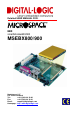
Detailed USER MANUAL FOR: EBX smartModule800/900 MSEBX800/900 Nordstrasse 11/F CH - 4542 Luterbach Tel.: ++41 (0)32 681 58 00 Fax: ++41 (0)32 681 58 01 Email: support@digitallogic.com Homepage: http://www.digitallogic.
DIGITAL-LOGIC AG MSEBX800/900 Detailed Manual V1.0 For internal use only: File: Path: MSEBX800-900_Detailed_V1.0.doc R:\HANDBUCH\MSEBX\MSEBX800\MSEBX800-900_Detailed_V1.0.doc COPYRIGHT 2008 BY DIGITAL-LOGIC AG This publication is protected by copyright and all rights are reserved.
DIGITAL-LOGIC AG MSEBX800/900 Detailed Manual V1.0 Table of Contents 1. PREFACE .....................................................................................................................................................5 1.1. Trademarks ..................................................................................................................................... 5 1.2. Disclaimer ..............................................................................................................
DIGITAL-LOGIC AG 7.2. 7.3. 8. MSEBX800/900 Detailed Manual V1.0 The 3pin Jumpers......................................................................................................................... 50 Jumpers on the MSEBX800......................................................................................................... 51 INDEX ........................................................................................................................................................
DIGITAL-LOGIC AG MSEBX800/900 Detailed Manual V1.0 1. PREFACE The information contained in this manual has been carefully checked and is believed to be accurate; it is subject to change without notice. Product advances mean that some specifications may have changed. DIGITAL-LOGIC AG assumes no responsibility for any inaccuracies, or the consequences thereof, that may appear in this manual.
DIGITAL-LOGIC AG 1.5. MSEBX800/900 Detailed Manual V1.0 Recycling Information All components within this product fulfill the requirements of the RoHS (Restriction of Hazardous Substances Directive). The product is soldered with a lead free process. 1.6. Technical Support 1. Contact your local DIGITAL-LOGIC Technical Support, in your country. 2. Use the Internet Support Request form at http://support.digitallogic.
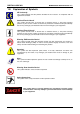
DIGITAL-LOGIC AG 1.8. MSEBX800/900 Detailed Manual V1.0 Explanation of Symbols CE Conformity This symbol indicates that the product described in this manual is in compliance with all applied CE standards. Caution, Electric Shock! This symbol and title warn of hazards due to electrical shocks (> 60V) when touching products or parts of them. Failure to observe the precautions indicated and/or prescribed by the law may endanger your life/health and/or result in damage to your equipment.
DIGITAL-LOGIC AG 1.9. MSEBX800/900 Detailed Manual V1.0 Applicable Documents and Standards The following publications are used in conjunction with this manual. When any of the referenced specifications are superseded by an approved revision, that revision shall apply. All documents may be obtained from their respective organizations. Advanced Configuration and Power Interface Specification Revision 2.
DIGITAL-LOGIC AG MSEBX800/900 Detailed Manual V1.0 Smart Battery Data Specification Revision 1.1, December 11, 1998. www.sbs-forum.org System Management Bus (SMBus) Specification Version 2.0, August 3, 2000 Copyright © 1994, 1995, 1998, 2000 Duracell, Inc., Energizer Power Systems, Inc., Fujitsu, Ltd., Intel Corporation, Linear Technology Inc., Maxim Integrated Products, Mitsubishi Electric Semiconductor Company, PowerSmart, Inc., Toshiba Battery Co. Ltd., Unitrode Corporation, USAR Systems, Inc.
DIGITAL-LOGIC AG MSEBX800/900 Detailed Manual V1.0 RoHS is often referred to as the "lead-free" directive but it restricts the use of the following substances: Lead Mercury Cadmium Chromium VI PBB and PBDE The maximum allowable concentration of any of the above mentioned substances is 0.1% (except for Cadmium, which is limited to 0.01%) by weight of homogeneous material.
DIGITAL-LOGIC AG MSEBX800/900 Detailed Manual V1.0 1.12. Swiss Quality 100% Made in Switzerland DIGITAL-LOGIC is a member of "Swiss-Label" This product was not manufactured by employees earning piecework wages This product was manufactured in humane work conditions All employees who worked on this product are paid customary Swiss market wages and are insured ISO 9000:2001 (quality management system) 1.13.
DIGITAL-LOGIC AG MSEBX800/900 Detailed Manual V1.0 2. OVERVIEW 2.1. Standard Features The MICROSPACE EBX is a miniaturized modular device incorporating the major elements of a PC/AT compatible computer. It includes standard PC/AT compatible elements, such as: 2.2. Powerful GEODE LX800/900 with 500/600MHz DDRAM 128-1024MByte SODIMM 200pin Real-time clock with CMOS-RAM and 10-year battery buffer LPT1 parallel port COM1-, COM2- RS232 serial port 16C550 comp.
DIGITAL-LOGIC AG 2.4. 2.4.1. MSEBX800/900 Detailed Manual V1.
DIGITAL-LOGIC AG 2.4.2. MSEBX800/900 Detailed Manual V1.
DIGITAL-LOGIC AG 2.5. MSEBX800/900 Detailed Manual V1.0 MSEBX800/900 Specifications CPU CPU SM800 CPU Core Supply st 1 Level Cache nd 2 Level Cache Performance SM800PCX SM900PCX Clock SM800PCX SM900PCX Specification AMD GEODE LX800/900 located in the smartModule800/900 1.
DIGITAL-LOGIC AG MSEBX800/900 Detailed Manual V1.0 External Interfaces Video Interfaces USB V1.1/2.0 LPT COM1 COM2 COM3 COM4 Keyboard Mouse Floppy Parallel-Hard disk 2.5” Parallel-Hard disk 3.5” Speaker ISA-Bus PCI-Bus PCI-Riser-Bus Specification CRT1, DVO 4 Ports IEEE1293 Printer RS232 RS232 PS/2 PS/2 26pin FCC Interface for TEAC Mini-Floppy 2 x 44pin RM2.0mm ATAIDE-cable 2 x 40pin RM2.5mm PATA-IDE cable 0.
DIGITAL-LOGIC AG Operating Temperature MSEBX800/900 Detailed Manual V1.
DIGITAL-LOGIC AG 2.6. MSEBX800/900 Detailed Manual V1.0 Examples of Ordering Codes The MSEBX800 system is combined from: Baseboard MSEBX800 smartModule 800/900-xxx (must be ordered separately) Memory: SODIMM200-DDRAM (must be ordered separately) Article Part No. MSEBX800 811060 SM800PCX SM900PCX Accessories MSFloppy MSFDCK MSEBX800-DK Options Option L+ DDRAM256M DDRAM512M DDRAM1G 805212 805242 Part No. 891001 802600 811210 Part No.
DIGITAL-LOGIC AG 2.7. MSEBX800/900 Detailed Manual V1.
DIGITAL-LOGIC AG MSEBX800/900 Detailed Manual V1.
DIGITAL-LOGIC AG MSEBX800/900 Detailed Manual V1.
DIGITAL-LOGIC AG 2.8. MSEBX800/900 Detailed Manual V1.0 Incompatibilities to a Standard PC/AT None. 2.9. # 80 MSEBX800/900 Related Application Notes Description High frequency Radiation (to meet EN55022) Application Notes are availble at http://www.digitallogic.com support, or on any Application CD from DIGITAL-LOGIC. 2.10. High Frequency Radiation (to meet EN55022/EN61000) All peripheral interfaces are filtered to meet the EMI/EMC standards EN55022.
DIGITAL-LOGIC AG MSEBX800/900 Detailed Manual V1.0 2.11. Thermoscan Product MSEBX800 SM800PCX SODIMM DDR 1GB Software Part Number Serial Number 811202 45320210010 805164 45316410032 870672 Windows XP SP2 running desktop Version 0.2 2.1 - Top view, passive cooled: t [min] 60 fCPU [MHz] 500 I [A] 0.5 P [W] 9.5 2.12. RTC Battery Lifetime Battery Specifications Lowest Temp. -40°C Manufacturer pbq Type ER10280 Capacity versus Temp. 8uA 850mAh Voltage versus Temp. 8uA 3.5V Nominal Values 3.
DIGITAL-LOGIC AG MSEBX800/900 Detailed Manual V1.0 3. PREPARATION 3.1. Important Information Warning, ESD Sensitive Device! Place the embedded computer board on an isolated, ESD-protected surface. Also ensure that all equipment, tools and people are fully protected against ESD. Attention! The smartModule must be firmly attached to the board with screws. Do not attempt to power-up the system without taking this step or the system may not work and you risk damaging the equipment! See Section 3.
DIGITAL-LOGIC AG 3.2. MSEBX800/900 Detailed Manual V1.0 Mounting the smartModule Line up the holes in the smartModule on the MSEBX board (top side). Then on the reverse side, attach the smartModule using 4 Phillips head screws (circled in red, within the red frame marking the approximate location of the smartModule). The screws are delivered with the smartModule but if lost may be ordered: Part Nr. 502528, description: M2x 5 galvanized machine screw.
DIGITAL-LOGIC AG 3.3. MSEBX800/900 Detailed Manual V1.0 RAM Assembly/Disassembly To install or change the RAM, follow these steps: 1. Unmount the smartModule by removing the 4 screws marked in red (see the photo from the previous page). 2. To change the RAM: a. Using your thumbnails, gently push the clips holding the RAM module in place toward the outside (Photo 1, marked "A"). Photo 1 b. There will be a slight "click" and the RAM will flip up at an angle (Photo 2). Photo 2 c.
DIGITAL-LOGIC AG MSEBX800/900 Detailed Manual V1.0 e. Slowly push the RAM down until the clips "click" into place (Photo 3). Photo 3 3. To install a RAM: a. Carefully place the side of the RAM with the connectors into the slot. There is only one correct way to place the RAM in the slot due to a notch between the connectors which matches up to a tab in the slot. Do not force the RAM into the slot, it should fit very easily. b. Slowly push the RAM down until the clips "click" into place (Photo 3).
DIGITAL-LOGIC AG 3.4. MSEBX800/900 Detailed Manual V1.0 Power & Reset Buttons Power Button: Push the Power Button for 2 seconds to start up the system. Reset Button: Should the system hang, press the Reset Button.
DIGITAL-LOGIC AG MSEBX800/900 Detailed Manual V1.0 4. BUS SIGNALS 4.1. PC104 Bus Note... The ISA-Bus may have some minor incompatibilities, see Chapter 6. AEN, output Address Enable: used to degate the microprocessor and other devices from the I/O channel to allow DMA transfers to take place. low = CPU Cycle, high = DMA Cycle BALE, output Address Latch Enable: provided by the bus controller and used on the system board to latch valid addresses and memory decodes from the microprocessor.
DIGITAL-LOGIC AG MSEBX800/900 Detailed Manual V1.0 /Master, input This signal is used with a DRQ line to gain control of the system. A processor or DMA controller on the I/O channel may issue a DRQ to a DMA channel in cascade mode and receive a /DACK. /MEMCS16, input MEMCS16 Chip Select: signals the system board if the present data transfer is a 1 wait-state, 16bit, memory cycle. It must be derived from the decode of LA17 through LA23.
DIGITAL-LOGIC AG MSEBX800/900 Detailed Manual V1.0 /SMEMW, input/output These signals instruct the memory devices to store the data present on the data bus for the first MByte. /SMEMW is active in all memory read cycles. /SMEMW may be driven by any microprocessor or DMA controller in the system. When a microprocessor on the I/O channel wishes to drive /SMEMW, it must have the address lines valid on the bus for one system clock period before driving /SMEMW active. Both signals are active low.
DIGITAL-LOGIC AG MSEBX800/900 Detailed Manual V1.0 5. DETAILED SYSTEM DESCRIPTION 5.1. Boot Time System Boot Times Definitions/Boot-Medium Quick Normal Boot* Boot time [s] MSEBX800-500MHz with RTC-Backup Battery Memory 256MB shared 8MB for Video From Floppy disk Boot from Setup-Disk1 MS-DOS v6.22 to "Starting MS-DOS"-Prompt. Boot from Setup-Disk1 MS-DOS v6.22 to "Welcome Setup Screen"-Prompt. Boot from "(Sys a:)-Disk“ to "A:/>“-Prompt.
DIGITAL-LOGIC AG 5.2. Interfaces 5.2.1. X31 Pin 1 3 6 X32 Pin 1 3 6 MSEBX800/900 Detailed Manual V1.0 PS/2 Keyboard (AT Compatible) and PS/2 Mouse Keyboard Signal KB_Data GND KB_Clk Pin 2 5 8 Signal +5Volt / 100mA - Pin 2 5 8 Signal +5Volt / 100mA - Mouse Signal MB_Data GND MB_Clk 5.2.2. Line Printer Port LPT1 A standard bi-directional LPT port is integrated into the MICROSPACE PC.
DIGITAL-LOGIC AG 5.2.4. MSEBX800/900 Detailed Manual V1.0 Floppy Disk Interface Supported Floppy Formats Capacity 1.2 MB 720 K 1.44 M Drive size 5-1/4" 3-1/2" 3-1/2" Tracks 80 80 80 Data rate 500 KHz 250 KHz 500 KHz DOS version 3.0 - 6.22 3.2 - 6.22 3.3 - 6.22 Floppy Interface Configuration The desired configuration of floppy drives (number and type) must be properly initialized in the board's CMOS – configuration memory. This is generally done by using DEL or F2 at bootup time.
DIGITAL-LOGIC AG 5.3. MSEBX800/900 Detailed Manual V1.0 Controllers 5.3.1. Interrupt Controllers An 8259A compatible interrupt controller, within the chipset, provides seven prioritized interrupt levels. Of these, several are normally associated with the board's onboard device interfaces and controllers, and several are available on the AT expansion bus.
DIGITAL-LOGIC AG 5.4. MSEBX800/900 Detailed Manual V1.0 BIOS Recovery In case the BIOS needs to be recovered: 1. Set Jumper J9. 2. Start the MSEBX800/900. 3. Open the BIOS. 4. Remove Jumper J9. 5. Load the default BIOS settings. 6. Save the settings. 7. Restart the MSEBX800/900.
DIGITAL-LOGIC AG MSEBX800/900 Detailed Manual V1.0 6.
DIGITAL-LOGIC AG 6.1. MSEBX800/900 Detailed Manual V1.
DIGITAL-LOGIC AG 6.2. X1 Pin 1 X2 Pin 1 3 5 7 9 11 13 15 17 19 X11 MSEBX800/900 Detailed Manual V1.0 Connector Descriptions Power Input Signal 8-30V DC-Input Pin 2 Signal Ground Pin 2 4 6 8 10 12 14 16 18 20 Signal +3.3V +5V +5V PWR-OK +12V -12V PS-ON# GND -5V +5V ATX Connector Signal +3.3V GND GND GND +5VSB +3.3V GND GND GND +5V LVDS Pin Signal Pin Signal 1 LVDS_A02 LVDS_A0+ 3 GND 4 GND 5 LVDS_A16 LVDS_A1+ 7 LCD BKL (dep. J5) 8 LCD BKL (dep.
DIGITAL-LOGIC AG X15 MSEBX800/900 Detailed Manual V1.0 LCD Connector Pin Signal Pin Signal 1 DE_SPLIT 2 VSYNC 3 BLK 4 HSYNC 5 VCCLCD_SB 6 Ground 7 NC 8 SHFCLK 9 VDD 10 D0 11 D1 12 D2 13 D3 14 D4 15 D5 16 D6 17 D7 18 D8 19 D9 20 D10 21 D11 22 D12 23 D13 24 D14 25 D15 26 Ground 27 D16 28 D17 29 D18 30 D19 31 D20 32 NC 33 D21 34 D22 35 D23 36 NC 37 NC 38 NC 39 NC 40 NC 41 NC 42 NC 43 NC 44 Ground 45 NC 46 NC 47 NC 48 NC 49 VCC 50 NC The LCD interface works only if the J6 Jumper is not installed.
DIGITAL-LOGIC AG MSEBX800/900 Detailed Manual V1.
DIGITAL-LOGIC AG X31 Pin 1 3 6 X32 Pin 1 3 6 MSEBX800/900 Detailed Manual V1.
DIGITAL-LOGIC AG MSEBX800/900 Detailed Manual V1.0 RJ45 Connector 10BaseT (IEEE 802.3i), 100BaseTX (IEEE 802.3u): MDI-Pin EIA/TIA 568A colors (wire/line) Pin Twisted Pair TX+ White / Green 1 3 TX- Green 2 3 RX+ White / Orange 3 2 GND .. 4 1 GND .. 5 1 6 2 GND .. 7 4 GND .. 8 4 RX- Cabling: X36 Orange Do not exceed 100m (328 feet); minimum quality of CAT5, preferably S/FTP or STP CAT6. Be careful to have a well balanced shield/ground concept.
DIGITAL-LOGIC AG X52 AVR Pin Signal 1 AVR VCC 3 AVR SCL 5 AVR MISO Only for internal use X53 Pin 1 3 5 7 9 11 13 15 17 19 X60 Pin 1 3 5 7 9 11 13 15 17 19 21 23 25 27 29 31 33 35 37 39 41 43 MSEBX800/900 Detailed Manual V1.
DIGITAL-LOGIC AG X62 Pin 1 3 5 7 9 11 13 15 17 19 21 23 25 27 29 31 33 35 37 39 X70 MSEBX800/900 Detailed Manual V1.0 3.
DIGITAL-LOGIC AG MSEBX800/900 Detailed Manual V1.
DIGITAL-LOGIC AG MSEBX800/900 Detailed Manual V1.0 X101 PC/104+ Connector (PCI) Pin 1 2 3 4 5 6 7 8 9 10 11 12 13 14 15 16 17 18 19 20 21 22 23 24 25 26 27 28 29 30 A: GND/5.0V KEY2 VI/O AD05 C/BE0* GND AD11 AD14 +3.3V SERR* GND STOP* +3.3V FRAME* GND AD18 AD21 +3.3V IDSEL0 AD24 GND AD29 +5V REQ0* GND GNT1* +5V CLK2 GND +12V -12V B: Reserved AD02 GND AD07 AD09 VI/O AD13 C/BE1* GND PERR* +3.3V TRDY* GND AD16 +3.
DIGITAL-LOGIC AG MSEBX800/900 Detailed Manual V1.0 X120 MiniPCI Interface Pin 1 3 5 7 9 11 13 15 17 19 21 23 25 27 29 31 33 35 37 39 41 43 45 47 49 51 53 55 57 59 61 Signal TIP 8PMJ-3 8PMJ-6 8PMJ-7 8PMJ-8 LED1_GRNP LED1_GRNN CHSGND INTB# 3.3V RESERVED GROUND CLK GROUND REQ# 3.
DIGITAL-LOGIC AG MSEBX800/900 Detailed Manual V1.0 X130 PCI Slot (Standard PCI Slot) Pin Name PCI Pin Description Pin Name PCI Pin Description A1 A2 A3 A4 A5 A6 A7 A8 A9 A10 A11 A12 A13 A14 A15 A16 A17 A18 A19 A20 A21 A22 A23 A24 A25 A26 A27 A28 A29 A30 A31 A32 A33 A34 A35 A36 A37 A38 A39 A40 A41 A42 A43 A44 A45 A46 A47 A48 A49 A50 A51 A52 A53 A54 A55 A56 A57 A58 A59 A60 A61 A62 TRST +12V TMS TDI +5V INTA INTC +5V ----+5V ----GND03 GND05 3.3Vaux RESET +5V GNT GND08 PME# AD30 +3.
DIGITAL-LOGIC AG MSEBX800/900 Detailed Manual V1.0 7. JUMPER LOCATIONS ON THE BOARD The following tables show the location of the jumper blocks on the MSEBX800/900 board. The numbers shown in these tables are silk screened on the board so that the pins can be easily located. This chapter refers to the individual pins for these jumpers. Be careful: some jumpers are soldering bridges; you will need a miniature soldering station with a vacuum pump. Settings written in bold are defaults! 7.1.
DIGITAL-LOGIC AG 7.3. MSEBX800/900 Detailed Manual V1.
DIGITAL-LOGIC AG MSEBX800/900 Detailed Manual V1.0 8. INDEX A H Addressing PCI Devices............................................. 31 High Frequency Radiation .......................................... 22 B I BIOS Recovery .......................................................... 36 Block Diagrams .......................................................... 13 Boot Time................................................................... 32 Bus Signals .................................................
DIGITAL-LOGIC AG MSEBX800/900 Detailed Manual V1.0 Mounting................................................................ 25 Specifications ............................................................. 15 SQS............................................................................ 11 Standards..................................................................... 8 Swiss Association for Quality and Management Systems................................................................. 11 Swiss Quality.....