MTEK6000 SERIES USER'S MANUAL MTEK6000 SERIES Electronic Flow Corrector & Monitoring Devices Installation and Operating Instructions January 2002 Part # 900315 January 2002
MTEK6000 SERIES USER'S MANUAL TABLE OF CONTENTS Chapter 1: Overview Overview ....................................................................................................... Hazardous Locations .................................................................................... Compliance ………….................................................................................... Warranty ………………................................................................................. Security Options ……………….....
MTEK6000 SERIES USER'S MANUAL Analog Sampling ……..................................................................……..…. Special Key Combinations …………………............................................... Assigning The Number of Displayed Digits .............................................. Viewing and Clearing Alarms from the Keypad ....................................... Calibration Mode ...........................................................................................
MTEK6000 SERIES USER'S MANUAL List of Figures Figure 1-1, MTEK6000 Exterior View . . . . . . . . . . . . . . . . . . . . . . . . . . . . . . . . Figure 1-2, MTEK6000 Interior View . . . . . . . . . . . . . . . . . . . . . . . . . . . . . . . . Figure 2-1, Power Connection and Configuration . . . . . . . . . . . . . . . . . . . . . . . Figure 2-2, Index Box Assembly . . . . . . . . . . . . . . . . . . . . . . . . . . . . . . . . . . . . Figure 2-3, Base Plate showing unit and index rotation . . . . . . . . .
MTEK6000 SERIES USER'S MANUAL Metretek, Inc. is a registered trademark and MTEK6000, MTEKManager, pcGas, Meter Reader, Customer Monitor, AutoPoll, Label Changer, Site I.D. Changer, Units Changer and Virtual Keypad are trademarks of Metretek, Inc. All other trademarks are the property of organizations not connected with Metretek, Inc. and are used for reference purposes only. All contents and specifications in this manual are subject to change without notice.
MTEK6000 SERIES USER'S MANUAL January 2002
MTEK6000 SERIES USER'S MANUAL CHAPTER 1: OVERVIEW NOTE: The MTEK6000 is similar in many respects to the Metretek AE6000 but there are also differences. The information in this manual applies only to the MTEK6000. The MTEK6000 series products are lowcost microprocessor-controlled, electronic devices for measuring gas flow and volumes or monitoring pressure and temperature for a system.
MTEK6000 SERIES USER'S MANUAL WARNING Substitution of components may impair suitability for Class 1, Division 1 and Class 1 Division 2 applications. COMPLIANCE The MTEK6000 device complies with Part 15 and Part 68 of the FCC Rule. See Appendix E for details. ONE-YEAR WARRANTY Metretek, Inc. warrants the products it manufactures to be totally free from any defects in materials and workmanship under normal operation and use. Metretek, Inc.
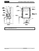
MTEK6000 SERIES USER'S MANUAL Figure 1-1 MTEK6000 exterior view January 2002 1-3
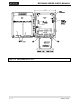
MTEK6000 SERIES USER'S MANUAL Figure 1-2 MTEK6000 interior view 1-4 January 2002
MTEK6000 SERIES USER'S MANUAL Chapter 2: Installation UNPACKING 1. Thoroughly examine the box to verify it was not damaged in shipping. If you find damage, immediately file a claim with the shipper. 5. If the unit is battery powered, verify that jumpers JP 19, 20 and 24 are in the A to B position. Load the battery pack with fresh batteries and connect it to the corrector at position J6. Repeat with the second battery pack connecting it at position J7 (see Fig. 2-1). Go to step 7. 2.
MTEK6000 SERIES USER'S MANUAL NOTE The flashing LCD display indicates an alarm condition (e.g. First Time Power). See Chapter 3 for information on alarms. 8. You can now view selected parameter values on the display by using the scroll switch. The scroll switch is activated by the use of a magnet (one is shipped with the unit). See Display Mode, in Chapter 3, for information about this function. B. MTEK6000 UPS power supply - an uninterruptible 12 VDC power supply with battery back up. C.
MTEK6000 SERIES USER'S MANUAL Output Shaft Rotation feet/revolution (ft3/rev) and 0.1, 1 and 10 cubic meters/revolution (m3/rev). To change the input drive value to 5 ft3/rev: To change the rotation of the output shaft to counterclockwise (figure 2-2): 1. Loosen set screw a on compound gear A. SETTING UP THE INDEX ASSEMBLY 1. Loosen set screw e on gear E. 2. Lower gear A until its upper teeth engage the upper teeth of compound gear B. 2. Disengage gear E from counter gear D. 3. Tighten set screw a.
MTEK6000 SERIES USER'S MANUAL NOTE When you box haveassembly changed contains the inputa drive The index reed value, be sure to remove the switch (G) and a correspondingexisting magnetdrive (F). value label from the window and replace The magnet should be positioned so there isit with- a0.1" new label that states the 0.07" clearance between the current magnetinput and drive value. For your convenience, switch. To adjust this clearance, refer to Fig. Metretek, supplies extra labels with the 1-3 on pageInc.
MTEK6000 SERIES USER'S MANUAL PULSE INPUT TO THE MTEK6000 Magnetically operated reed switches inside the meter drive assembly send electronic pulses as the drive turns. These pulses represent uncorrected meter volume to the instrument. To eliminate false counts that can result from the reed switch "bounce”, the MTEK6000 uses a set/reset, dual-reed switch configuration.
MTEK6000 SERIES USER'S MANUAL Figure 2- 5 Wall Mounting Figure 2- 3 Wall Mounting Figure 2- 4 Pipe Mounting 2-6 January 2002
MTEK6000 SERIES USER'S MANUAL TRANSDUCERS IN THE MTEK6000 The MTEK6000 uses a precision strain gauge pressure transducer mounted inside the unit, combining maximum accuracy with low power consumption. To sense gas temperature, the MTEK6000 employs a highly linear and stable device, a platinum resistive temperature detector (RTD). Case temperature sensing is accomplished with an on-board precision reference integrated circuit (IC).
MTEK6000 SERIES USER'S MANUAL Figure 2- 7 Typical Installation for MTEK6000 EFC Figure 2- 6 Typical Installation for MTEK6000 EFM 2-8 January 2002
MTEK6000 SERIES USER'S MANUAL INSTALLING THE THERMAL PROBE A thermal (temperature) probe is connected to the MTEK6000 by a 6-foot (2-meter) cable. You should coil excess cable to prevent possible damage. The probe is designed to fit into standard Metretek, Inc. thermowells. Optional 15-foot (4.5 meter) and 30-foot (9-meter) cables are available. See Fig 2-10. To install the thermal probe, use the supplied temperature probe adapter. Refer to Table 2-1.
MTEK6000 SERIES USER'S MANUAL INSTALLING THE PULSE OUTPUT WIRING The MTEK6000 comes standard with a board installed that provides two optically isolated pulse outputs. These outputs are configurable as either Form C or Form A type outputs. An alternative version of the board is available that provides four pulse outputs. Both versions of the board also provide terminal block positions to access the uncorrected mechanical volume switch output of the index. See Fig. 2-11 for pulse output wiring.
MTEK6000 SERIES USER'S MANUAL Volume and Alarm Pulse Specifications Uncorrected Pulse Output Specifications 1. All pulse outputs are isolated from ground and each other. Provides 1,500 volts between input and output and between contact sets. 2. Form C: DC load only, 125mWdc max, 50Vdc max Form A: AC or DC load 800mW max, 400V max., 100mA max, continuous 3. Configurable pulse width from 1 to 5,000 milliseconds (ms). 1. 2. 3. 4.
MTEK6000 SERIES USER'S MANUAL COMMUNICATIONS Modem Communications (2400 Baud) To communicate with the MTEK6000, the Site ID (RUID) in the device must be the same as the Site ID entered in the software package. The Site ID is a unique identification number (1 to 65,535) that allows the Metretek, Inc. software packages to communicate with the MTEK6000. The default Site ID number is 1. Software can be used to enter a number other than the default.
MTEK6000 SERIES USER'S MANUAL Table 2-2 Activity Indicator MTEK6000 Function (RS232 cable connected) Activity Indicator RS-232C cable connected 1 long blink Set #1 Pulse received 1 short blink Reset #1 Pulse received 2 short blinks Set #2 Pulse received 3 short blinks Reset #2 Pulse received 4 short blinks RS-232C cable disconnected 3 long blinks after a few seconds delay January 2002 2-13
MTEK6000 SERIES USER'S MANUAL Figure 2- 10 Corrector Board connection and jumper configuration diagram 2-14 January 2002
MTEK6000 SERIES USER'S MANUAL GROUNDING The information presented here is merely a guideline to help customers avoid surge damage to the MTEK6000. None of these guidelines are to be construed as replacing or superseding rules and practices defined by the National Electrical Code (NEC), or the Classification of Gas Utility Areas for Electrical Installations guidelines, as published by the American Gas Association (AGA) or other regulatory agency.
MTEK6000 SERIES USER'S MANUAL 2-16 January 2002
MTEK6000 SERIES USER'S MANUAL Chapter 3 : Operating Modes • • The MTEK6000 operates in any of five modes: • Sleep • Display • Alarm • Configuration (requires Virtual keypad, Meter Reader 4.10 or later, or pcGas Host software, or the optional external keypad and display) • Calibration (requires Virtual keypad, Meter Reader 4.10 or later, software or the optional external keypad and display) • Calling the unit via modem. Waking up on a specified number of pulses set by the Wake Up On Pulse parameter.
MTEK6000 SERIES USER'S MANUAL ALARM MODE alarms using the magnet: The MTEK6000 can be configured to activate an alarm when certain conditions are met or when user defined limits are exceeded. You can display active alarm messages on the optional external keypad and display or alarm codes on the standard display. The unit can also automatically call a host computer running Metretek, Inc. software programs to report alarms. 1. Apply the magnet to the scroll switch until the outer display shows AL XXXXXX.
MTEK6000 SERIES USER'S MANUAL For transport or interruptible customers, this parameter can be used to alarm when an account has exceeded a predetermined daily volume allocation. Faulty Counter Alarm (EFC) This alarm is only valid for EFC units with a Form C switch. If any of the dual-reed switches in the index assembly fail, pulses to the unit would automatically switch to a working counter input.
MTEK6000 SERIES USER'S MANUAL Low Pressure Alarm If the gas pressure should fall below the Low Pressure Alarm Setpoint, a Low Pressure alarm will be initiated. The alarm will remain active until the pressure rises above the Low Pressure Reset parameter value. The setpoints are user configurable with default values of -100 and -80 respectively (see Appendix A for parameter addressing for your device).
MTEK6000 SERIES USER'S MANUAL # of Record = Open Door Alarm (optional) The Open Door (tamper) alarm is initiated when the door of the MTEK6000 opens. When this occurs, a full wake-up is triggered and the MTEK6000 executes its processes. The alarm is inactive when the door is closed. Software Error Alarm If there is a fault in the software, the Software Error alarm will initiate.
MTEK6000 SERIES USER'S MANUAL Configuration Mode Configuration mode allows you to set-up the MTEK6000's initial configuration; change any of the operating parameter values, and set alarm conditions and limits. MTEKManager version 1.x or the optional external keypad and display are required to perform configuration. See the MTEKManager on-line help for operating instructions. MTEKManager version 1.x is supplied, upon request, with your unit consisting of Virtual Keypad and other utilities.
MTEK6000 SERIES USER'S MANUAL Figure 3 - 1 Optional Keypad and Display January 2002 3 -7
MTEK6000 SERIES USER'S MANUAL Assigning Function Keys In configuration mode, any parameter can be assigned to a function key. To assign a function key: 1. Enter configuration mode by pressing conf (use the password, if required). 2. Display the desired parameter. Press jump followed by the address of the parameter, and then press ent (see Appendix A for parameter addressing for your device). 3. Assign a function key to the parameter.
MTEK6000 SERIES USER'S MANUAL Example: A value of 1 will produce a 1 Hz (once per second) and a value of 10 a .10 Hz (once every 10 seconds) sampling rate. Set to 0 to disable. NOTE Analog sampling will impact battery life in battery-operated systems. It is only recommended for AC or properly sized Solar power systems. Special Key Combinations There are a number of special key combinations that allow the user to view system information and perform certain tasks very easily.
MTEK6000 SERIES USER'S MANUAL CALIBRATION MODE Calibration mode allows the user to calibrate any of the analog signals, such as the pressure transducer or the temperature probe. While operating in the calibration mode, the MTEK6000 continues to store pulses and periodically updates volume, pressure, and temperature data using the values measured when calibration mode was initially entered. Once in calibration mode, the user can perform the following operations: 1. Calibrate zero only. 2.
MTEK6000 SERIES USER'S MANUAL As with the zero point, if the external reference matches the default span value, simply press ent. Otherwise, key in the current value of the external reference, then press ent. After pressing ent, the display reading should immediately adjust to reflect the new calibration point. Pressing esc instead of ent at this point aborts the operation and returns the operator to the calibration prompt. 9. Steps 4 - 8 are required only once.
MTEK6000 SERIES USER'S MANUAL Calibrating the Differential Transmitter (EFM Only) Pressure the differential pressure sensor and wait for the reading to stabilize NOTE Pressing esc repeatedly from anywhere within the calibration procedure will back the operator out of calibration mode. 9. Press span. The unit now shows: 1. Display the differential pressure by pressing F8 or jumping to 040302. As with the zero point, if the external reference matches the default span value, simply press ent.
MTEK6000 SERIES USER'S MANUAL CHAPTER 4: OPTIONAL EQUIPMENT ANALOG OUTPUT (AO) OPTION The Analog Output Module (part # 10210001B-001) and connecting cable (part # 1002-0245B-001) provides a two-wire, loop-powered, optically isolated, precision 4-20mA output. This module interfaces with the MTEK6000 series product line to provide a 4-20mA output for flow rate, pressure, or numerous other control and monitoring applications.
MTEK6000 SERIES USER'S MANUAL Figure 4 - 1 Analog Output Option 4-2 January 2002
MTEK6000 SERIES USER'S MANUAL MTEK6000 ANALOG OUTPUT SPECIFICATIONS Environmental Operating Temperature or Operating Humidity -30°C to + 70°C -22°F to 158°F 0 to 95% noncondensing Electrical Isolation 500 V DC or AC RMS (sine wave) between digital interface and 4-20 mA loop. Current Loop Output Maximum Output Current 24mA Minimum Output Current 3.5mA Maximum Supply Voltage 50V Minimum Supply Voltage 8V Resolution 16 bits, 0.00024 mA Full Scale %Error ±0.
MTEK6000 SERIES USER'S MANUAL Therefore, 0% = 4mA, 25% = 8mA, 50% = 12mA, 75% = 16mA, & 100% = 20mA. 6. If adjustments are needed, press zero. The display now shows: zero: x.xxx 04.000 +y.yyy mA x.xxx represents the default zero value (low scale) and y.yyy is the adjustment made to 4mA for the analog output signal. The adjustment can either be positive or negative shown by + or - respectively. The top line will alternate between zero: x.xxx and UP/DN TO ADJUST.
MTEK6000 SERIES USER'S MANUAL Chapter 5 : MAINTENANCE and SOFTWARE PACKAGES Changing the Battery To replace the battery in the unit: As with any device based on solid-state electronics, actual maintenance of the MTEK6000 should be minimal. However, there are certain guidelines that, if followed, will minimize device failure and increase the product’s service life. 1.
MTEK6000 SERIES USER'S MANUAL Software Important Note: pcGas Meter Reader, pcGas Host and pcGas Customer Monitor applications are DOS based programs. They are available for a one-time charge but are sold ‘as is’ and are not being changed or upgraded in any way by Metretek. While these programs may be of value to certain users, Metretek makes no warranty as to their performance. Metretek strongly encourages the use of the MTEKManager and DC2000 32 bit Windowstm applications.
MTEK6000 SERIES USER'S MANUAL DC2000 The MTEK6000 is fully compatible with Metretek’s DC2000. DC2000 is Metretek’s flagship collection and management software system for energy data. DC2000’s scaleability and flexibility enables users to choose from a wide range of functions and data throughput configurations. This protects your investment by letting you continuously adapt your system to operate in proportion to your business needs.
MTEK6000 SERIES USER'S MANUAL 5-4 January 2002
MTEK6000 SERIES USER'S MANUAL APPENDIX A: PROCESS CONFIGURATION STANDARD The MTEK6000 uses Process configuration for database organization and management. Table A-1: Standard display mode and function keys for MTEK6000 EFC Label I.D.
MTEK6000 SERIES USER'S MANUAL Table A-4: Standard display mode and function keys for MTEK6000 EFC w/ Aux Pressure Label I.D.
MTEK6000 SERIES USER'S MANUAL Table A-7: Standard display mode and function keys for MTEK6000 EFC w/2 Aux Pressure Label I.D.
MTEK6000 SERIES USER'S MANUAL Table A-9: Standard history data stored in the MTEK6000 EFC w/ 2 Aux Pressure Table A-10: Standard display mode and function keys for MTEK6000 EFC2 w/2 40 days of daily corrected volume 40 days of daily uncorrected volume 40 days of daily maximum flow rate 40 days of daily minimum flow rate 40 days of daily average pressure 40 days of daily maximum pressure 40 days of daily minimum pressure 40 days of daily average aux. pressure 1 40 days of daily average aux.
MTEK6000 SERIES USER'S MANUAL Table A-11: Standard alarms MTEK6000 EFC2 w/2 Aux Press Alarms First Time Power Low Supply Volts LowVolt Shutdown Software Error Lost Pressure Lost Temperature Lost Aux 1 Press Lost Aux 2 Press High Flow Rate 1 Low Flow Rate 1 Curr Day Volume 1 Faulty Counter 1 High Flow Rate 2 Low Flow Rate 2 Cur Day Volume 2 Faulty Counter 2 High Pressure Low Pressure High Temperature Low Temperature High Aux 1 Press Low Aux 1 Press High Aux 2 Press Low Aux 2 Press Open Door Switch 1 Alarm Sw
MTEK6000 SERIES USER'S MANUAL Table A-13: Standard display mode and function keys for MTEK6000 EFM w/ Aux Press Table A-14: Standard alarms MTEK6000 EFM w/ Aux Press Alarms Label I.D.
MTEK6000 SERIES USER'S MANUAL Table A-16: Standard display mode and function keys for MTEK6000 EPR Table A-18: Standard history data stored in the MTEK6000 EPR Label I.D.
MTEK6000 SERIES USER'S MANUAL Table A-19: Standard display mode and function keys for MTEK6000 ETR Table A-21: Standard history data stored in the MTEK6000 ETR Label I.D.
MTEK6000 SERIES USER'S MANUAL Table A-22: Standard display mode and function keys for MTEK6000 EPTR Label I.D.
MTEK6000 SERIES USER'S MANUAL A-10 January 2002
MTEK6000 SERIES USER'S MANUAL APPENDIX B: CALCULATIONS AGA-7 Volume Calculations The MTEK6000 EFC performs volume calculations based on the Ideal Gas Law. Boyle’s Law is used for pressure and Charles’s Law for temperature. These laws state that the volume of any definite weight of a perfect gas varies inversely with change in absolute pressure and directly with change in absolute temperature. The unit can perform such calculations for turbine, rotary, and diaphragm displacement meters.
MTEK6000 SERIES USER'S MANUAL B -2 January 2000
MTEK6000 SERIES USER'S MANUAL APPENDIX C: PARAMETER DESCRIPTION The parameters relative to the operation and configuration of the MTEK6000 are listed below (See Appendix A for the addresses of these parameters). Alarm Pulse Output Enable/Disable The EFC can generate a generic pulse output on any alarm condition. This parameter enables the pulse output through Relay #2. Enter 35.7 to enable or 0.0 to disable. The Default value is 0.
MTEK6000 SERIES USER'S MANUAL Base Temperature The Base Temperature parameter appears as a factor in the Corrected Volume calculation. It is one of the factors used to correct the flowing volume, as registered by the meter itself, to the base volume used for calculating “Standard Volume”. The default value of this parameter is 60.000 degrees F. Calibrate Mode Time-out The fractional portion of this parameter is the Calibrate Mode Time-out.
MTEK6000 SERIES USER'S MANUAL Cubic Unit/Pulse In or Meter Drive This parameter determines the volume unit represented by one input pulse, and is normally set to equal the drive (CF/Rev) of the meter. Standard indexes produce one pulse per revolution; therefore, the CF/Pulse will equal the drive rate of the meter. The Default value is 100.
MTEK6000 SERIES USER'S MANUAL Flow Units The flow units parameter reflects the time used to represent the flow rate. For example, if the flow rate represents cubic feet per hour, this parameter should be set to Hour. The Default value is 2. Minute Hour Day 1 2 3 Gas Day Roll Time HHMM (Hours, Minutes) This item is used in Daily and Monthly history modes to determine when the gas day ends. The time is entered in military time. For example, a standard roll time of 8:00AM is entered as 800.0.
MTEK6000 SERIES USER'S MANUAL Low Pressure Alarm Setpoint The setpoint at which the unit determines that there is a Low Pressure alarm condition. The Default value is -100. Low Supply Voltage Alarm Reset After a Low Supply Voltage alarm occurs, the setpoint at which the unit exits this condition is entered in this location. The Default is 8.0. Low Supply Voltage Alarm Setpoint The setpoint at which the unit determines that there is a Low Supply Voltage alarm condition. The Default is 8.5.
MTEK6000 SERIES USER'S MANUAL Supercompressibilty Calculated or Fixed This parameter is used to set the mode for supercompressibility calculations. If it is set to 0, then a new supercompressibility value will be calculated each time the process executes. If set to 1, the unit will use the value set in the Fixed Supercompressibility Value parameter for calculations. The Default value is 0.
MTEK6000 SERIES USER'S MANUAL It is disabled if set to 0. In this mode, the EFC should be configured to wake up on the number of pulses entered along with an hourly scheduled wake-up to record history data. Therefore, the wake up interval (seconds) parameter should be set to 3600. The Default value is 0. Units of Measure The MTEK6000 can be configured to calculate volume and flow with English or Metric units.
MTEK6000 SERIES USER'S MANUAL C-8 January 2002
MTEK6000 SERIES USER'S MANUAL APPENDIX D : BOARD JUMPER POSITIONS 61-SBC Revision A – Corrector Board January 2002 D-1
MTEK6000 SERIES USER'S MANUAL 61-OPT Revision A – Option Board Pulse Output 1: Use Terminal 19 (normally open contact) Terminal 18 (common 1) and Terminal 17 (normally closed contact) For form A output: put JP1 and JP1A both in position A to B. For form C output: put JP1 and JP1A both in position B to C (requires external wetting).
MTEK6000 SERIES USER'S MANUAL JP6 selects a power source for external analog transducers at TB3-1 & TB6-1 as follows: Description use on board +12V dc supply ( 20 mA max ) use on-board +5V dc supply ( 20 mA max) Vin external supply (from Metretek UPS) Jumper position JP6 = A JP6 = B JP6 = C External Analog #2: Use Terminal 35 (transducer power) Terminal 36 (transducer output) Terminal 37 (transducer common) For a 4-to-20 mA type transducer put JP7 and JP8 in.
MTEK6000 SERIES USER'S MANUAL 50-PLI Revision C - Phone Line Interface J1: Connections from the PLI to the Corrector board J3: Telephone line connection J4: Earth Ground (for surge suppression) connection JP5: position 2-3 shorts R9 sometimes required when barriers cause too much drop in the OH signal level (default position is 1-2).
MTEK6000 SERIES USER'S MANUAL APPENDIX E : Certifications (CSA, UL and FCC Drawings and Statements CONSUMER INFORMATION AND FCC REQUIREMENTS 1. The Federal Communication commission (FCC) has established rules, which permits this device to be directly connected to the telephone network. Standardized jacks are used for these connections. This equipment should not be used on party lines or coin lines. 2.
MTEK6000 SERIES USER'S MANUAL CANADIAN “INDUSTRY CANADA” NOTICE The Industry Canada label identifies certified equipment. This certification means that the equipment meets telecommunications network Protective, operational and safety requirements as prescribed in the appropriate Terminal Equipment Technical Requirements document(s). The Department does not guarantee the equipment will operate to the user’s satisfaction.
MTEK6000 SERIES USER'S MANUAL EL0001 (Sheet 1 of 2) : Class I Division 2 Installation January 2002 E-3
MTEK6000 SERIES USER'S MANUAL EL0001 (Sheet 2 of 2) : Class I Division 2 Installation E-4 January 2002
MTEK6000 SERIES USER'S MANUAL APPENDIX F: Warranty Information WARRANTY INFORMATION The seller warrants its hardware to be free from defects in material and workmanship under normal and proper use for a period of one year from the date the hardware is shipped from Metretek, Incorporated.
MTEK6000 SERIES USER'S MANUAL F-2 January 2002
MTEK6000 SERIES USER'S MANUAL APPENDIX G: TII Station Protector January 2002 G-1
MTEK6000 SERIES USER'S MANUAL G-2 January 2002
MTEK6000 SERIES USER'S MANUAL APPENDIX H: Hazardous Area Installation Control Drawings October 2002 H-1
MTEK6000 SERIES USER'S MANUAL October 2002 H-2
MTEK6000 SERIES USER'S MANUAL October 2002 H-3