b Maintenance and Service Guide Compaq Notebook Evo N150 Series Document Part Number: 238849-001 June 2001 This guide is a troubleshooting reference used for maintaining and servicing the notebook. It provides comprehensive information on identifying computer features, components, and spare parts, troubleshooting computer problems, and performing computer disassembly procedures.
© 2001 Compaq Computer Corporation Compaq, the Compaq logo, Armada, and Deskpro Registered in U. S. Patent and Trademark Office. Evo is a trademark of Compaq Information Technologies Group, L.P. in the U.S. and other countries. Microsoft, MS-DOS, Windows, and Windows NT are trademarks of Microsoft Corporation in the United States and other countries. Intel, Pentium, and Celeron are trademarks of Intel Corporation in the United States and other countries.
Contents 1 Product Description 1.1 Models and Features . . . . . . . . . . . . . . . . . . . . . . . . . 1–1 Models . . . . . . . . . . . . . . . . . . . . . . . . . . . . . . . . . . . . 1–2 Features . . . . . . . . . . . . . . . . . . . . . . . . . . . . . . . . . . . 1–5 1.2 Clearing a Password. . . . . . . . . . . . . . . . . . . . . . . . . . 1–6 1.3 Power Management . . . . . . . . . . . . . . . . . . . . . . . . . . 1–7 1.3 External Computer Components . . . . . . . . . . . . . . . . 1–8 1.
2.15 No Audio, Part 1 . . . . . . . . . . . . . . . . . . . . . . . 2.16 No Audio, Part 2 . . . . . . . . . . . . . . . . . . . . . . . 2.17 Non Functioning Device . . . . . . . . . . . . . . . . . 2.18 Non Functioning Keyboard . . . . . . . . . . . . . . . 2.19 Non Functioning Pointing Device . . . . . . . . . . 2.20 Network or Modem Connection . . . . . . . . . . . 2–18 2–19 2–20 2–21 2–22 2–23 3 Illustrated Parts Catalog 3.1 Serial Number Location . . . . . . . . . . . . . . . . . . . . . . . 3–1 3.
.8 EMI Shield . . . . . . . . . . . . . . . . . . . . . . . . . . . . . . . . 5.9 Top Cover. . . . . . . . . . . . . . . . . . . . . . . . . . . . . . . . . 5.10 TouchPad . . . . . . . . . . . . . . . . . . . . . . . . . . . . . . . . 5.11 Speakers . . . . . . . . . . . . . . . . . . . . . . . . . . . . . . . . . 5.12 Microphone . . . . . . . . . . . . . . . . . . . . . . . . . . . . . . 5.13 Display Lid Switch Board . . . . . . . . . . . . . . . . . . . 5.14 Heat Sink . . . . . . . . . . . . . . . . . . .
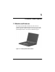
1 Product Description 1.1 Models and Features The Compaq Notebook Evo N150 Series offer advanced modularity, Intel Pentium III and Intel Celeron processors with 64-bit architecture, industry-leading Accelerated Graphics Port (AGP) implementation, and extensive multimedia support. Figure 1-1.
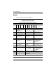
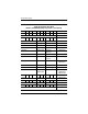
Product Description Models Computer models are shown in Table1-1. Table 1-1 Compaq Notebook Evo N150 Models and Model Naming Conventions Key N15 P 800 T4X 15 V C 64 8L ME XXXXXX-XXX 1 2 3 4 5 6 7 8 9 10 11 Key Description Options 1 Brand / Series designator N=Notebook 15=150 2 Processor type P=Intel Pentium III C=Intel Celeron 3 Processor speed 800=800 MHz 700=700MHz 4 Display type / size / resolution T=TFT 4=14.x-inch X=XGA (1024 × 768) 5 Hard drive size 15=15.
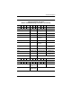
Product Description Table 1-1 Compaq Notebook Evo N150 Models and Model Naming Conventions (Continued) 1 2 3 4 5 6 7 8 9 10 11 N15 P 800 T4X 15 V C 64 8L ME 470013-XXX Belgium 470013-663 Norway 470013-668 Czech Republic 470013-735 Portugal 470013-748 Denmark 470013-664 Russia 470013-749 France 470013-737 Saudi Arabia 470013-734 French Canada 470013-662 Slovakia / Slovenia 470013-669 Germany 470013-739 Spain 470013-751 Greece / Poland 470013-665 Sweden / Finla
Product Description Table 1-1 Compaq Notebook Evo N150 Models and Model Naming Conventions (Continued) 1 2 3 4 5 6 7 8 9 10 11 N15 C 700 T4X 15 D C 64 8L ME 470013-XXX Taiwan N15 470013-659 C 700 T4X 10 D C 64 8L ME 470013-XXX Asia / Pacific 470013-658 The Netherlands 470013-713 Australia 470013-731 Norway 470013-621 Belgium 470013-619 Portugal 470013-714 Czech Republic 470013-701 Russia 470013-718 Denmark 470013-620 Slovakia / Slovenia 470013-622 France
Product Description Features Processors, varying by computer model: 800-MHz Intel Pentium III Processor with 256-KB integrated cache 700-MHz Intel Celeron Processor with 128-KB integrated cache 64-MB high-performance Synchronous DRAM (SDRAM), expandable to 512 MB Integrated Trident CyberBlade i1 with AGP 2X support 14.1-inch, XVGA, TFT (1024 × 768) display, with over 16.8 million colors 15- or 10-GB high-capacity hard drive Full-size TouchPad keyboard Mini PCI 56K V.
Product Description Connectors for: RJ-11 modem universal serial bus stereo line out/headphone parallel serial external keyboard/mouse RJ-45 network external monitor AC power Stereo speakers providing Compaq PremierSound 16-bit stereo sound 1.2 Clearing a Password If the notebook you are servicing has an unknown password, follow these steps to clear the password. These steps also clear CMOS. 1. Prepare the computer for disassembly. Refer to Section 5.
Product Description 4. Replace the RTC battery and reassemble the computer. 5. Connect AC power to the computer. Do not reinsert any battery packs at this time. 6. Turn on the computer. All passwords and all CMOS settings are clear. 1.3 Power Management The computer comes with a collection of power management features that extend battery operating time and conserve power.
Product Description 1.3 External Computer Components The external components on the front and left side of the computer are shown in Figure 1-2 and described in Table 1-2. . Figure 1-2. Front and Left Side Components Table 1-2 Front and Left Side Panel Components Item Component Function 1 Security cable slot Attaches an optional security cable to the computer. 2 Vent Allows airflow to cool internal components.
Product Description Table 1-2 Front and Left Side Panel Components (Continued) Item Component Function 3 Air intake vent Cools internal components. 4 RJ-11 jack (internal modem models only) Connects the modem cable to an internal modem. A modem cable is included with internal modem models. 5 USB connector Connects USB devices. 6 PC Card slots (2) Support a 32-bit (CardBus) or 16-bit PC Card. 7 PC Card eject buttons Eject a PC Card from a PC Card slot.
Product Description The computer right side and rear panel components are shown in Figure 1-3 and described in Table 1-3. Figure 1-3. Right Side and Rear Panel Components Table 1-3 Right Side and Rear Panel Components Item Component Function 1 Media Bay Accepts a diskette drive, CD- or DVD-ROM drive, or secondary battery pack. 2 Infrared port Links to another IrDA-compliant device for wireless communication.
Product Description Table 1-3 Right Side and Rear Panel Components (Continued) Item Component Function 3 Parallel connector Connects a parallel device. 4 Serial connector Connects a serial device. 5 Keyboard/mouse connector Connects an external keyboard or PS/2-compatible external mouse. To connect a keyboard and a mouse at the same time, use an optional Y-adapter. 6 RJ-45 jack (network models only) Connects the network cable. A network cable is not included with the computer.
Product Description The keyboard components are shown in Figure 1-4 and described in Table 1-4. Figure 1-4.
Product Description Table 1-4 Keyboard Components Item Component Function 1 F1 through F12 Perform preset functions. function keys 2 Embedded numeric keypad Converts keys to numeric keypad. 3 Cursor control keys Move the cursor around the screen. 4 Windows application key Displays a menu when using a Microsoft application. The menu is the same that is displayed by pressing the right mouse button. 5 Windows logo key Displays the Windows Start menu.
Product Description The components on the top of the computer are shown in Figure 1-5 and described in Table 1-5. Figure 1-5. Top Components Table 1-5 Top Components Item Component Function 1 Power button Turns on the computer. To turn off the computer, use the operating system Shut Down command. 2 Drive light indicator Turns on when the hard drive, CD-, or DVD-ROM drive is accessed.
Product Description Table 1-5 Top Components (Continued) Item Component Function 3 Diskette drive light Turns on when the diskette drive in the Media Bay or the optional external diskette drive is accessed. 4 Num lock light On: Num lock is on and the embedded numeric keypad is enabled. 5 Caps lock light On: Caps lock is on. 6 Scroll lock light On: Scroll is on. 7 Microphone Inputs single-channel sound to the computer; can be used whether the computer is open or closed.
Product Description The external components on the bottom of the computer are shown in Figure 1-6 and described in Table 1-6. Figure 1-6. Bottom Components Table 1-6 Bottom Components Component Function 1 Media Bay release latch Releases the Media Bay device from the connector. 2 Serial number Identifies the computer; needed when you call Compaq customer support.
Product Description Table 1-6 Bottom Components (Continued) Component Function 3 Reset button Manually resets the system if a failure occurs. Resetting the Å WARNING: computer will cause unsaved information to be lost. Before performing a reset, close all applications and shut down Windows, if possible. 4 Fan Provides airflow to cool internal components.
Product Description 1.4 Design Overview This section presents a design overview of key parts and features of the computer. Refer to Chapter 3, “Illustrated Parts Catalog,” to identify replacement parts, and Chapter 5, “Removal and Replacement Procedures,” for disassembly steps.
2 Troubleshooting Å WARNING: Only authorized technicians trained by Compaq should repair this equipment. All troubleshooting and repair procedures are detailed to allow only subassembly/module level repair. Because of the complexity of the individual boards and subassemblies, no one should attempt to make repairs at the component level or to make modifications to any printed wiring board. Improper repairs can create a safety hazard.
Troubleshooting Using the PhoenixBIOS Setup Utility The PhoenixBIOS Setup Utility (PSU) is built into the system. You can configure the system BIOS and modify or restore factory default settings, such as date and time, types of disk drives, power management, and password settings. To run PSU, press F10 during system startup. When the main screen displays, use the keyboard and arrow keys to move around the menus and make selections.
Troubleshooting Troubleshooting Flowcharts Table 2-1 Troubleshooting Flowcharts Overview Section Description 2.1 Initial troubleshooting 2.2 No power, part 1 2.3 No power, part 2 2.4 No power, part 3 2.5 No power, part 4 2.6 No video, part 1 2.7 No video, part 2 2.8 Non functioning docking station 2.9 No operating system (OS) loading 2.10 No OS loading from hard drive, part 1 2.11 No OS loading from hard drive, part 2 2.12 No OS loading from hard drive, part 3 2.
Troubleshooting 2.1 Initial Troubleshooting Begin Troubleshooting N Go to Section 2.2, No Power Is there power? Y N Check LED board, speaker connections. Beeps, LEDs, or error Messages? N Y Go to Section 2.17, Non Functioning Device All drives working? N Y Go to Section 2.6, No Video Is there video? (no boot) N Keyboard/ pointing device working? Y N Y Go to Section 2.9, No OS Loading Is the OS loading? N Connecting to network or modem? Y N Is there sound? Y Go to Section 2.
Troubleshooting 2.2 No Power, Part 1 No Power (Power LED is off) Remove from docking station if applicable. N N Power up on battery power? Go to Section 2.3, No Power, Part 2 Power up on battery power? *Reset power. Y Y N N Power up on AC power? Power up on AC power? *Reset power. Y Go to Section 2.4, No Power, Part 3 Y Y Power up in docking station? Done N 1. Reseat power cables in docking station and at the AC outlet. 2. Ensure AC power source is active. 3.
Troubleshooting 2.3 No Power, Part 2 Continued from Section 2.2, No Power, Part 1 Visually check for debris in battery socket and clean if necessary Y Power on? Done N Check battery by recharging, moving to another computer, or replacing it. N Power on? Replace power supply, (if applicable) Y N Done Power on? Go to Section 2.
Troubleshooting 2.4 No Power, Part 3 Continued from Section 2.3, No Power, Part 2 Plug directly into AC outlet. Y Power LED on? Done N Reseat AC adapter in computer and at power source. Y Power on? Done N N Power outlet active? External Try different outlet. Y Internal or external AC adapter? Internal N Go to Section 2.5, No Power, Part 4 Replace power cord. Power on? Y Y Power on? Replace external AC adapter.
Troubleshooting 2.5 No Power, Part 4 Continued from Section 2.4, No Power, Part 3 Open computer. Y Loose or damaged parts? N Reseat loose components and boards and replace damaged items. Close computer and retest. N Power on? 1. Internal DC-DC converter* 2. Internal AC adapter 3. Processor board* 4. System board* Y Done 2–8 Replace the following items, if applicable. Check computer operation after each replacement: * Replace these items as a set to prevent shorting out among the components.
Troubleshooting 2.6 No Video, Part 1 No Video Docking Station Standalone or Docking Station? Go to Section 2.7, No Video, Part 2 * Note: To change from internal to external display, use the hotkey combination. Standalone Internal or external display*? Y Adjust brightness. Depress lid switch to ensure operation. A Adjust brightness. Y Video OK? Done N Internal External Video OK? Y Video OK? Done Done N N Replace the following one at a time. Test after each replacement: 1.
Troubleshooting 2.7 No Video, Part 2 Continued from Section 2.6, No Video, Part 1 Remove notebook from docking station, if connected. Adjust display brightness. Check brightness of external monitor. N Y Go to “A” in Section 2.6, No Video, Part 1. Video OK? Y Video OK? Done N Check for notebook properly seated in docking station, bent pins on cable, and for monitor connection. Try another external monitor.
Troubleshooting 2.8 Non Functioning Docking Station (if applicable) Reseat power cord in docking station and power outlet. Check voltage setting on docking station. Reinstall notebook into docking station. Y Reset monitor cable connector at docking station. Docking station operating? Done N Y Docking station operating? Done N Remove notebook, reseat all internal parts, and replace any damaged items in docking station.
Troubleshooting 2.9 No Operating System (OS) Loading Reseat power cord in docking station and power outlet. No OS loading from Hard drive, go to Section 2.10. No OS loading form Diskette drive, go to Section 2.13. No OS loading from CD- or DVD-ROM drive, go to Section 2.14. No OS loading from Network, go to Section 2.20. Note: Before beginning, always check cable connections, cable ends, and drives for bent or damaged pins.
Troubleshooting 2.10 No OS Loading from Hard Drive, Part 1 OS not loading from hard drive. Y Nonsystem disk message? N Go to Section 2.11, No OS Loading from Hard Drive, part 2. Reseat external hard drive. Y OS loading? Done N N Boot from CD? N Y Boot from diskette? Check the setup utility for correct booting order. Y Go to Section 2.13, No OS Loading from Diskette Drive. Change boot priority through the setup utility and reboot.
Troubleshooting 2.11 No OS Loading from Hard Drive, Part 2 Continued from Section 2.10, No OS Loading from Hard Drive, Part 1 Reseat hard drive. N 1. Replace hard drive. 2. Replace system board. CD or diskette in drive? Y Access hard drive? Y Done N Remove diskette and reboot. Run FDISK. Y Boot from hard drive? N Done N Create partition, then format hard drive to bootable C:\ prompt. Hard drive partition? Y N Boot from diskette drive? Y N Go to Section 2.
Troubleshooting 2.12 No OS Loading from Hard Drive, Part 3 Continued from Section 2.11, No OS Loading from Hard Drive, Part 2. N System files on hard drive? Install OS and reboot. Y Y Y Virus on hard drive? OS loading from hard drive? Clean virus. N Done N Y Run SCANDISK and check for bad sectors. Diags on diskette? Replace hard drive. N N Can bad sectors be fixed? Run diags and follow recommendations Replace hard drive. Y N Fix bad sectors. Boot from hard drive? Replace hard drive.
Troubleshooting 2.13 No OS Loading from Diskette Drive Y OS not loading from diskette drive. Reseat diskette drive. OS loading? Done N N Y NonSystem Disk message? Bootable diskette in drive? N Install bootable diskette and reboot computer. Y N Go to Section 2.17, Non Functioning Device. Boot from another device? Check diskette for system files. Try different diskette. Y N Diskette drive enabled in the setup utility? Y Enable drive and cold boot computer. Y 1. Replace diskette drive. 2.
Troubleshooting 2.14 No OS Loading from CD- or DVD-ROM Drive Y No OS loading from CD- or DVD-ROM drive. N Bootable disk in drive? Disk in drive? N Y Install bootable disk and reboot computer. Try another bootable disk. Install bootable disk. Y Boots from CD or DVD? Done N Y Reseat drive. Boots from CD or DVD? Done N N Booting from another device? Y Y Booting order correct? N Go to Section 2.17, Non Functioning Device. Clear CMOS. Refer to Section 1.
Troubleshooting 2.15 No Audio, Part 1 Y Turn up audio internally or externally. No audio. Audio? Done N N Y Notebook in docking station (if applicable)? N Go to Section 2.16, No Audio, Part 2. Internal audio? Undock Y Go to Section 2.16, No Audio, Part 2. Replace the following docking station components one at a time as applicable. Check after each change. 1. Reseat docking station audio cable. 2. Replace audio cable. 3. Replace speaker. 4. Replace docking station audio board. 5.
Troubleshooting 2.16 No Audio, Part 2 Continued from Section 2.15, No Audio, Part 1. N Audio driver in OS configured? Reload audio drivers. Y N Correct drivers for application? Load drivers and set configuration in OS. Y Connect to external speaker. N Audio? Y Replace audio board and speaker connections in notebook, if applicable. Y Audio? Done N 1. Replace internal speakers. 2. Replace audio board, if applicable. 3. Replace system board.
Troubleshooting 2.17 Non Functioning Device Non functioning device Reseat device. Unplug the Non Functioning device from the notebook, inspect cables and plugs for bent or broken pins or other damage. Y Any physical device? Fix or replace broken item. Possible bad hard drive. Replace drive. Go to Section 2.9, No OS Loading. Clear CMOS. N Reattach device. Close notebook, plug in power, and reboot. N Device boots properly? Y Done 2–20 Possible bad NIC. Replace card.
Troubleshooting 2.18 Non Functioning Keyboard Keyboard not operating properly. Connect notebook to good external keyboard. N External device works? Replace system board. Y Reseat internal keyboard connector (if applicable). N Replace internal keyboard or cable. OK? Y Y OK? Done Done N Replace system board.
Troubleshooting 2.19 Non Functioning Pointing Device Pointing device not operating properly. Connect notebook to good external pointing device. N External device works? Replace system board. Y Reseat internal pointing device connector (if applicable). N OK? Replace internal pointing device or cable. Y Y OK? Done Done N Replace system board.
Troubleshooting 2.20 Network or Modem Connection No network or modem connection. N Network or modem jack active? Replace jack or have jack activated. Y Y Connect to non digital line. Digital line? N N NIC/modem configured in OS? Y Reload drivers and reconfigure. OK? Done N Y Disconnect all power from the notebook and open. Replace NIC/modem if applicable. Y Reseat NIC/modem if applicable. OK? Done N Replace system board.
3 Illustrated Parts Catalog This chapter provides an illustrated parts breakdown and a reference for spare part numbers. 3.1 Serial Number Location When ordering parts or requesting information, provide the computer serial number and model number located on the bottom of the computer (Figure 3-1). Figure 3-1.
Illustrated Parts Catalog 3.2 Computer System Major Components Figure 3-2.
Illustrated Parts Catalog Table 3-1 Computer System Major Components Item Description Spare Part Number 1 14.
Illustrated Parts Catalog Computer System Major Components (continued) 3–4 Maintenance and Service Guide
Illustrated Parts Catalog Table 3-1 Computer System Major Components (Continued) Item 7a 7b Description Spare Part Number Speakers 239043-001 Left speaker Right speaker 8 TouchPad (TouchPad bracket included in Hardware Kit, spare part number 239052-001) 239046-001 9 Heat sink 239038-001 10 PC Card assembly 239040-001 11 Hard drives 15 GB 10 GB 12 239037-001 239036-001 System boards (includes 64 MB SDRAM) 800 MHz Intel Pentium III 700 MHz Intel Celeron 239051-001 239050-001 13 Disk c
Illustrated Parts Catalog Computer System Major Components (continued) 3–6 Maintenance and Service Guide
Illustrated Parts Catalog Table 3-1 Computer System Major Components (Continued) Item Description 15 Mini PCI Communications Boards Type III mini PCI combination 56 Kbps modem/NIC board Type III mini PCI 56 Kbps modem board 16 Spare Part Number 233558-001 233557-001 Media Bay devices Diskette drive 24X Max CD-ROM drive CD-RW drive 8X Max DVD-ROM drive 17 Base enclosure 18 Battery packs 8-cell Lithium ion (Li ion) 6-cell Lithium ion (Li ion) Maintenance and Service Guide 239035-001 239033-001
Illustrated Parts Catalog 3.3 Miscellaneous Plastics Kit Components Figure 3-3.
Illustrated Parts Catalog 3.4 Miscellaneous Hardware Kit Components Figure 3-4.
Illustrated Parts Catalog 3.5 Cable Kit Components Figure 3-5.
Illustrated Parts Catalog 3.6 Mass Storage Devices Figure 3-6.
Illustrated Parts Catalog 3.
Illustrated Parts Catalog Table 3-6 Miscellaneous Spare Parts (not illustrated) (Continued) Description Spare Part Number External AC adapter 50W slim AC adapter 163444-001 163444-291 Logo kit 233556-001 Memory expansion boards 256 MB 128 MB 64 MB 167136-001 135244-001 135243-001 Screw kit (Includes the screws and screwlock listed below. Refer to Appendix C, “Screw Listing,” for more information about screw specifications and usage.) M2.5 × 8 M2.5 × 7 M2.5 × 4.5 M2.5 × 3 M2 × 14.
4 Removal and Replacement Preliminaries This chapter provides essential information for proper and safe removal and replacement service. 4.1 Tools Required You will need the following tools to complete the removal and replacement procedures: Magnetic screwdriver Phillips P0 screwdriver 5 mm socket Tool kit (includes connector removal tool, loopback plugs, and case utility tool) 4.
Removal and Replacement Preliminaries Plastic Parts Using excessive force during disassembly and reassembly can damage plastic parts. Use care when handling the plastic parts. Apply pressure only at the points designated in the maintenance instructions. Cables and Connectors Cables must be handled with extreme care to avoid damage. Apply only the tension required to unseat or seat the cables during removal and insertion. Handle cables by the connector whenever possible.
Removal and Replacement Preliminaries Before handling a drive, ensure that you are discharged of static electricity. While handling a drive, avoid touching the connector. Handle drives on surfaces that have at least one inch of shock-proof foam. Avoid dropping drives from any height onto any surface. After removing a hard drive, CD-ROM drive, or a diskette drive, place it into a static-proof bag. Avoid exposing a hard drive to products that have magnetic fields such as monitors or speakers.
Removal and Replacement Preliminaries 4.4 Preventing Electrostatic Damage Many electronic components are sensitive to electrostatic discharge (ESD). Circuitry design and structure determine the degree of sensitivity. Networks built into many integrated circuits provide some protection, but in many cases the discharge contains enough power to alter device parameters or melt silicon junctions.
Removal and Replacement Preliminaries Place reusable electrostatic-sensitive parts from assemblies in protective packaging or non conductive foam. Use transporters and conveyers made of antistatic belts and roller bushings. Ensure that mechanized equipment used for moving materials is wired to ground and that proper materials were selected to avoid static charging. When grounding is not possible, use an ionizer to dissipate electric charges. 4.
Removal and Replacement Preliminaries 4.7 Grounding Equipment and Methods Grounding equipment must include either a wrist strap or a foot strap at a grounded workstation. When seated, wear a wrist strap connected to a grounded system. Wrist straps are flexible straps with a minimum of one megaohm ±10% resistance in the ground cords. To provide proper ground, wear a strap snugly against the skin at all times. On grounded mats with banana-plug connectors, connect a wrist strap with alligator clips.
Removal and Replacement Preliminaries Non-conductive plastic bags, tubes, or boxes Metal tote boxes Electrostatic voltage levels and protective materials Table 4-1 shows how humidity affects the electrostatic voltage levels generated by different activities.
5 Removal and Replacement Procedures This chapter provides removal and replacement procedures. All screws removed during disassembly are P0 Phillips screws. There are 64 screws and screwlocks in 13 different sizes that must be removed and replaced when servicing the computer. Make special note of each screw size and location during removal and replacement. Refer to Appendix C, “Screw Listing,” for detailed information on screw sizes, locations, and usage.
Removal and Replacement Procedures 5.1 Serial Number Report the computer serial number to Compaq when requesting information or ordering spare parts. The serial number is located on the bottom of the computer (Figure 5-1). Figure 5-1.
Removal and Replacement Procedures 5.2 Disassembly Sequence Chart Use the following chart to determine the section number to be referenced when removing computer components. Table 5-1 Disassembly Sequence Chart Section Description # of Screws Removed 5.3 Preparing the computer for disassembly 0 5.4 Computer feet 0 5.5 Hinge covers 0 5.6 Keyboard 2 5.7 Display 4 5.8 EMI shield 1 5.9 Top cover 18 5.10 TouchPad 5 5.11 Speakers 10 5.12 Microphone 0 5.
Removal and Replacement Procedures 5.3 Preparing the Computer for Disassembly Perform the following steps before disassembling the computer. Consult the computer Hardware Guide for instructions on the following steps: 1. Turn off the computer. 2. Disconnect the AC Adapter and all external devices. 3. Remove the battery pack. 4. Remove the hard drive. 5. Remove the Media Bay device. 5.4 Computer Feet The computer feet are adhesive-backed rubber pads.
Removal and Replacement Procedures 5.5 Hinge Covers The hinge covers are included in the Miscellaneous Plastics Kit (spare part number 239039-001). 1. Prepare the computer for disassembly (Section 5.3). 2. Turn the computer top side up with the front facing you. 3. Open the computer. 4. Use a flat blade screwdriver to pry up on the front edge of the left and right hinge covers (Figure 5-3). Figure 5-3. Removing the Hinge Covers 5. Remove the hinge covers.
Removal and Replacement Procedures 5.6 Keyboard Keyboard Cover Spare Part Number Information Keyboard Czech Danish European French French Canadian German Hebrew Hungarian International Italian Japanese 239054-221 239054-081 239054-021 239054-051 239054-121 239054-041 239054-BB1 239054-211 239054-002 239054-061 239054-291 Korean Norwegian Portuguese Russian Spanish Swedish Swiss Taiwanese Turkish U.K. English U.S.
Removal and Replacement Procedures 3. Remove the two pewter M2.5 × 7.0 screws keyboard to the top cover (Figure 5-4). that secure the 4. Lift up the back edge of the keyboard and swing it up and forward until it rests on the top cover. 5. Release the zero insertion force (ZIF) connector to which the keyboard cable is connected and disconnect the keyboard cable . Figure 5-4. Removing the Keyboard 6. Remove the keyboard. Reverse the above procedure to install the keyboard.
Removal and Replacement Procedures 5.7 Display Display Spare Part Number Information 14.1-inch, XGA, CTFT display 239029-001 When the display screws are removed, the display assembly is unsupported. Make sure to provide support for the display assembly when removing the display screws. 1. Prepare the computer for disassembly (Section 5.3). 2. Remove the hinge covers (Section 5.5). 3. Disconnect the display cable from the system board (Figure 5-5). 4. Remove the four silver M2.5 × 8.
Removal and Replacement Procedures 5. Remove the display. To ensure proper alignment of the display during replacement, loosely install the screws in the , , , sequence indicated in Figure 5-6. Tighten the screws after all four have been been loosely installed. After tightening the display screws, tuck the display cable into the slot in the base enclosure. Figure 5-6. Installing the Display Screws Reverse the above procedure to install the display.
Removal and Replacement Procedures 5.8 EMI Shield The EMI shield is included in the Miscellaneous Hardware Kit (spare part number 239052-001). 1. Prepare the computer for disassembly (Section 5.3) and remove the following components: a. Hinge covers (Section 5.5) b. Keyboard (Section 5.6) c. Display (Section 5.7) 2. Remove the black M2 × 12.5 screw that secures the EMI shield to the base enclosure (Figure 5-7). 3.
Removal and Replacement Procedures 5.9 Top Cover Top Cover Spare Part Number Information Top cover 239044-001 There are 18 screws in three different sizes that must be removed and replaced during replacement of the top cover. Make special note of each screw size and location when removing and replacing screws. 1. Prepare the computer for disassembly (Section 5.3) and remove the following components: a. Hinge covers (Section 5.5) b. Keyboard (Section 5.6) c. Display (Section 5.7) d.
Removal and Replacement Procedures 3. Remove the following screws: Nine pewter M2.5 × 7.0 screws from the recesses in the bottom of the computer (Figure 5-8) Two black M2.5 × 4.5 screws computer from the bottom of the from the battery bay Three black M2.5 × 4.5 screws from the rear panel of One silver M2 × 5.5 screw computer Figure 5-8.
Removal and Replacement Procedures 4. Turn the computer top side up with the front facing you. 5. Disconnect the display lid switch board , microphone and right and left speaker cables (Figure 5-9). , 6. Release the ZIF connector to which the TouchPad cable is connected and disconnect the TouchPad cable . Figure 5-9.
Removal and Replacement Procedures 7. Remove the two pewter M2.5 × 7.0 screws and the black M2.5 × 4.5 screw that secure the top cover to the base enclosure (Figure 5-10). 8. Lift the back edge of the top cover forward. and swing it up and Figure 5-10. Removing the Top Cover 9. Remove the top cover. Reverse the above procedure to install the top cover.
Removal and Replacement Procedures 5.10 TouchPad TouchPad Spare Part Number Information TouchPad 239046-001 TouchPad Bracket (included in Miscellaneous Hardware Kit) 239052-001 1. Prepare the computer for disassembly (Section 5.3) and remove the following components: a. Hinge covers (Section 5.5) b. Keyboard (Section 5.6) c. Display (Section 5.7) d. EMI shield (Section 5.8) e. Top cover (Section 5.9) 2. Turn the top cover bottom side up with the front facing you.
Removal and Replacement Procedures 3. Remove the two silver M2.5 × 3.0 screws and the three black M2.5 × 4.0 screws that secure the TouchPad bracket and TouchPad to the top cover (Figure 5-11). Figure 5-11.
Removal and Replacement Procedures 4. Release the ZIF connector to which the TouchPad cable is attached and disconnect the TouchPad cable (Figure 5-12). 5. Slide the TouchPad bracket top cover. toward the back of the 6. Remove the TouchPad bracket top cover. and TouchPad from the Figure 5-12. Removing the TouchPad Reverse the above procedure to install the TouchPad.
Removal and Replacement Procedures 5.11 Speakers Speakers Spare Part Number Information Speakers 239043-001 1. Prepare the computer for disassembly (Section 5.3) and remove the following components: a. Hinge covers (Section 5.5) b. Keyboard (Section 5.6) c. Display (Section 5.7) d. EMI shield (Section 5.8) e. Top cover (Section 5.9) 2. Turn the top cover bottom side up with the front facing you.
Removal and Replacement Procedures 3. Remove the two M2.5 × 4.5 screws that secure the top cover shield to the top cover (Figure 5-13). 4. Remove the right speaker cable from the clips top cover shield. and in the Figure 5-13.
Removal and Replacement Procedures 5. Remove the eight silver M2 × 5.5 screws speakers to the top cover (Figure 5-14). 6. Remove the speakers from the top cover that secure the . Figure 5-14. Removing the Speakers 5–20 Reverse the above procedure to install the speakers. The left and right speakers are not interchangeable. The right speaker has a longer speaker cable and must be installed in the right speaker position.
Removal and Replacement Procedures 5.12 Microphone The microphone is included in the Cable Kit (spare part number 239041-001). 1. Prepare the computer for disassembly (Section 5.3) and remove the following components: a. Hinge covers (Section 5.5) b. Keyboard (Section 5.6) c. Display (Section 5.7) d. EMI shield (Section 5.8) e. Top cover (Section 5.9) 2. Turn the top cover bottom side up with the front facing you.
Removal and Replacement Procedures 3. Remove the microphone from the slot the top cover (Figure 5-15). in which it rests in 4. Remove the microphone cable from the top cover slot through which it is routed. 5. Turn the top cover top side up. 6. Remove the microphone cable from the clip rests in the top cover shield. in which it Figure 5-15. Removing the Microphone Reverse the above procedure to install the microphone.
Removal and Replacement Procedures 5.13 Display Lid Switch Board The display lid switch board is included in the Cable Kit (spare part number 239041-001). 1. Prepare the computer for disassembly (Section 5.3) and remove the following components: a. b. c. d. e. Hinge covers (Section 5.5) Keyboard (Section 5.6) Display (Section 5.7) EMI shield (Section 5.8) Top cover (Section 5.9) 2. Turn the top cover bottom side up with the front facing you. 3. Remove the silver M1 × 4.
Removal and Replacement Procedures 5.14 Heat Sink The heat sink assembly includes the fan. The fan should not be removed from the heat sink assembly. Heat Sink Spare Part Number Information Heat sink 239038-001 1. Prepare the computer for disassembly (Section 5.3) and remove the following components: a. Hinge covers (Section 5.5) b. Keyboard (Section 5.6) c. Display (Section 5.7) d. EMI shield (Section 5.8) e. Top cover (Section 5.
Removal and Replacement Procedures 2. Disconnect the fan cable (Figure 5-17). from the system board 3. Remove the modem cable from the clip in the heat sink . 4. Remove the four black M2 × 4.0 screws and the pewter M2.5 × 7.0 screw that secure the heat sink to the base enclosure. 5. Remove the heat sink. Figure 5-17. Removing the Heat Sink The fan and heat sink are spared as one assembly. Do not remove the fan from the heat sink. Reverse the above procedure to install the heat sink.
Removal and Replacement Procedures 5.15 Infrared Board Infrared Board Spare Part Number Information Infrared board 239045-001 1. Prepare the computer for disassembly (Section 5.3) and remove the following components: a. Hinge covers (Section 5.5) b. Keyboard (Section 5.6) c. Display (Section 5.7) d. EMI shield (Section 5.8) e. Top cover (Section 5.
Removal and Replacement Procedures 2. Disconnect the infrared board cable (Figure 5-18). from the system board 3. Remove the infrared board cable from the metal clip through which it is routed. 4. Remove the black M2 × 4.0 screw board to the base enclosure. 5. Lift the infrared board that secures the infrared out of the base enclosure. Figure 5-18. Removing the Infrared Board Reverse the above procedure to install the infrared board.
Removal and Replacement Procedures 5.16 System Board There are 11 screws and screwlocks in five different sizes that must be removed and replaced when replacing the system board. Make special note of each screw size and location when removing and replacing screws. System Board Spare Part Number Information System boards (includes 64 MB SDRAM) 800 MHz Intel Pentium III 700 MHz Intel Celeron 239051-001 239050-001 1. Prepare the computer for disassembly (Section 5.
Removal and Replacement Procedures 3. Remove the six 5.0-mm screwlocks from the rear panel of the computer (Figure 5-19). Figure 5-19.
Removal and Replacement Procedures 4. Position the base enclosure so the front faces you. 5. Remove the following screws, as illustrated in Figure 5-20: two black M2 × 14.5 screws that secure the PC Card assembly to the base enclosure black M2.5 × 4.5 screw near the USB connector that secures the system board to the base enclosure black M2.5 × 4.0 screw that secures the modem connector/cable to the base enclosure black M2 × 4.
Removal and Replacement Procedures 6. Lift up the front edge of the system board until the board and the battery connector are clear of the base enclosure (Figure 5-21). Ä CAUTION: When removing the system board, make sure the battery connector is carefully routed out of the opening in the base enclosure in which it rests. Failure to follow this caution can result in damage to the battery connector. Figure 5-21.
Removal and Replacement Procedures 7. Slide the system board out of the base enclosure at an angle (Figure 5-22). Figure 5-22. Removing the System Board Reverse the above procedure to install the system board.
Removal and Replacement Procedures 5.17 PC Card Assembly PC Card Assembly Spare Part Number Information PC Card assembly 239040-001 1. Prepare the computer for disassembly (Section 5.3)) and remove the following components: a. Hinge covers (Section 5.5) b. Keyboard (Section 5.6) c. Display (Section 5.7) d. EMI shield (Section 5.8) e. Top cover (Section 5.9) f. Infrared board (Section 5.15) g. System board (Section 5.16) 2. Turn the system board bottom side up with the PC Card slot opening facing you.
Removal and Replacement Procedures 3. Peel back the shielding tape that covers the right PC Card screw (Figure 5-23). 4. Remove the two silver M2 × 5.0 screws PC Card assembly to the system board. that secure the 5. Turn the system board top side up with the PC Card slot opening facing you. 6. Lift up the back edge of the PC Card assembly to disconnect it from the system board . 7. Remove the PC Card assembly. Figure 5-23.
Removal and Replacement Procedures 5.18 Mini PCI Board Mini PCI Board Spare Part Number Information Mini PCI boards Type III mini PCI combination 56 Kbps modem/NIC board Type III mini PCI 56 Kbps modem board 233558-001 233557-001 1. Prepare the computer for disassembly (Section 5.3) and remove the following components: a. Hinge covers (Section 5.5) b. Keyboard (Section 5.6) c. Display (Section 5.7) d. EMI shield (Section 5.8) e. Top cover (Section 5.9) f. Infrared board (Section 5.15) g.
Removal and Replacement Procedures 3. Disconnect the modem connector/cable from the mini PCI board (Figure 5-24). 4. Set the modem connector/cable aside. 5. Pull away the plastic retention clips on each side of the mini PCI board . The board tilts upward. 6. Lift the edge of the board and slide it out of the mini PCI slot at a 45-degree angle . Figure 5-24. Removing the Mini PCI Board Reverse the above procedure to install the mini PCI board.
Removal and Replacement Procedures 5.19 Disk Cell RTC Battery Disk Cell RTC Battery Spare Part Number Information Disk cell RTC battery 236359-001 1. Prepare the computer for disassembly (Section 5.3) and remove the following components: a. Hinge covers (Section 5.5) b. Keyboard (Section 5.6) c. Display (Section 5.7) d. EMI shield (Section 5.8) e. Top cover (Section 5.9) f. Infrared board (Section 5.15) g. System board (Section 5.16) 2.
Removal and Replacement Procedures 3. Lift the edge of the RTC battery to disconnect and remove it from its socket (Figure 5-25). Figure 5-25. Removing the Disk Cell RTC Battery Reverse the above procedure to install the disk cell RTC battery.
6 Specifications This chapter provides physical and performance specifications. Table 6-1 Computer Dimensions Height Depth Width Weight (with 14.1-inch TFT display and Li ion battery) 12.2 in 1.3 in 9.8 in 309 mm 34 mm 248 mm 5.9 lb 2.7 kg Standalone (Battery) Power Requirements Nominal operating voltage (Li ion) Nominal operating voltage (6-cell Li ion) 14.8 VDC 11.
Specifications Table 6-1 Computer (Continued) Relative Humidity (non condensing) Operating Nonoperating 10 to 90% relative humidity 5 to 95% relative humidity, 101.6°F/38.7°C Maximum wet bulb temperature Altitude (unpressurized) Operating Nonoperating 0 to 10,000 ft 0 to 30,000 ft 0 to 3,048 m 0 to 9,144 m Shock Operating Nonoperating 10 G, 11 ms, half sine 60 G, 11 ms, half sine Vibration Operating Nonoperating 6–2 0.5 G zero-to-peak, 10 to 500 Hz, at 0.5 oct/min sweep rate 1.
Specifications Table 6-2 14.1-inch XGA, TFT Display Dimensions Height Depth Width 8.42 in 11.22 in 14.10 in Number of colors Up to 262K Contrast ratio 180:1 Brightness >150 nits typical 214 mm 285 mm 358 mm Pixel resolution Pitch Format Configuration 0.279 × 0.279 mm 1024 × 768 RGB vertical stripe Backlight Cold cathode fluorescent, 1 tube Character display 80 × 25 Refresh 60 Hz Total Power Consumption 8.
Specifications Table 6-3 Hard Drives 15 GB 10 GB User capacity per drive1 15.0 GB 10.0 GB Drive height (with drive frame) 0.37 in/9.5 mm 0.37 in/9.5 mm Drive width (with drive frame) 2.5 in/63.5 mm 2.5 in/63.5 mm Interface type ATA-5 ATA-5 3.0 ms 13.0 ms 24.0 ms 3.0 ms 13.0 ms 24.
Specifications Table 6-3 Hard Drives (Continued) 15 GB 10 GB 25,800 2 398 - 731 512 25,800 2 398 - 731 512 Buffer size3 512 KBytes 512 KBytes Disk rotational speed 4200 rpm 4200 rpm 100 155 - 286 100 155 - 286 Physical configuration Cylinders3 Heads3 Sectors per track3 Bytes per sector Transfer rate Interface max (Mbytes/sec)2 Media (Mbits/sec)3 1 1 GB = 1,000,000,000 bytes System capability may differ. 3 Actual drive specifications may differ slightly.
Specifications Table 6-4 Diskette Drive Diskette size 3.5 inch Light On system Height 0.5 in Bytes per sector 512 88 mm 12.7 mm Sectors per track High density Low density 18 (1.44 MB) 9 Tracks per side High density Low density 80 80 Read/write heads 2 15 (1.
Specifications Table 6-5 CD-ROM Drive Applicable disk CD-ROM (Mode 1, 2, and 3) CD-XA ready (Mode 2, Form 1 and 2) CD-I ready (Mode 2, Form 1 and 2) CD-R (read only) CD Plus Photo CD (single/multisession) CD-Extra Video CD CD-WO (fixed packets only) CD-Bridge Center hole diameter .59 in Disk diameter 120 mm, 80 m Disk thickness 1.2 mm Track pitch 1.
Specifications Table 6-6 DVD-ROM Drive Applicable disk DVD-5, DVD-9, DVD-10 CD-ROM (Mode 1 and 2) CD Digital Audio CD-XA ready (Mode 2, Form 1 and 2) CD-I ready (Mode 2, Form 1 and 2) CD-R (read only) CD Plus Photo CD (single/multisession) CD-Bridge Center hole diameter .59 in Disk diameter 120 mm, 80 mm Disk thickness 1.2 mm Track pitch .74 µ 15 mm Access time Random Full Stroke < 150 ms < 225 ms Audio output level Lineout Headphone Cache buffer 0.
Specifications Table 6-7 AC Adapter Weight Power supply (input) Operating voltage Operating current Operating frequency range Maximum transient Maintenance and Service Guide 100 to 240 VAC RMS Nominal 1.
Specifications Table 6-8 Battery Packs Dimensions Lithium ion (Li ion) Height Length Width Weight Cells Nickel Metal Hydride (NiMH) Height Length Width Weight Cells .82 in 3.78 in 5.28 in .86 lb 8 21 mm 96 mm 134 mm .39 kg .67 in 6.16 in 5.51 in 17 mm 131 mm 140 mm 6 Energy Li ion Voltage Amp-hour capacity Watt-hour capacity NiMH Voltage Amp-hour capacity Watt-hour capacity 14.8 V 3.8 Ah 53.5 Wh 11.1 V 3.1 Ah 34.
Specifications Table 6-9 System DMA Hardware DMA System Function DMA0 Available for audio DMA1 Entertainment audio (default; alternate = DMA0, DMA3, none) DMA2 Diskette drive DMA3 ECP parallel port LPT1 (default; alternate = DMA0, none) DMA4 DMA controller cascading (not available) DMA5 Available for PC Card DMA6 not assigned not assigned DMA7 PC Card controller can use DMA 1, 2, or 5.
Specifications Table 6-10 System Interrupts Hardware IRQ System Function IRQ0 System timer IRQ1 Keyboard controller IRQ2 Cascaded IRQ3 COM2 IRQ4 COM1 IRQ5 Audio (default)* IRQ6 Diskette drive IRQ7 Parallel port IRQ8 Real time clock (RTC) IRQ9 Infrared IRQ10 System use IRQ11 System use IRQ12 Internal point stick or external mouse IRQ13 Coprocessor (not available to any peripheral) IRQ14 IDE interface (hard drive and optical drive) System use IRQ15 PC Cards may assert IRQ
Specifications Table 6-11 System I/O Addresses I/O Address (hex) System Function (shipping configuration) 000 - 00F DMA controller no. 1 010 - 01F unused 020 - 021 Interrupt controller no.
Specifications Table 6-11 System I/O Addresses (Continued) I/O Address (hex) System Function (shipping configuration) 0A2 - 0BF unused 0C0 - 0DF DMA controller no.
Specifications Table 6-11 System I/O Addresses (Continued) I/O Address (hex) System Function (shipping configuration) 2F0 - 2F7 unused 2F8 - 2FF Infrared port 300 - 31F unused 320 - 36F unused 370 - 377 Secondary diskette drive controller 378 - 37F Parallel port (LPT1/default) 380 - 387 unused 388 - 38B FM synthesizer - OPL3 38C - 3AF unused 3B0 - 3BB VGA 3BC - 3BF Reserved (parallel port/no EPP support) 3C0 - 3DF VGA 3E0 - 3E1 PC Card controller in CPU 3E2 - 3E3 unused 3E8 -
Specifications Table 6-12 System Memory Map Size Memory Address System Function 640 K 00000000 - 0009FFFF Base memory 128 K 000A0000 - 000BFFFF Video memory 48 K 000C0000 - 000CBFFF Video BIOS 160 K 000C8000 - 000E7FFF unused 64 K 000E8000 - 000FFFFF System BIOS 15 M 00100000 - 00FFFFFF Extended memory 58 M 01000000 - 047FFFFF Super extended memory 58 M 04800000 - 07FFFFFF unused 2M 08000000 - 080FFFFF Video memory (direct access) 4G 08200000 - FFFEFFFF unused 64 K FFFF000
A Connector Pin Assignments Table A-1 Stereo Speaker/Headphone Pin Signal Pin Signal 1 Audio out 2 Ground Table A-2 Microphone Pin Signal Pin Signal 1 Audio in 2 Ground Maintenance and Service Guide A–1
Connector Pin Assignments Table A-3 External Keyboard/Mouse 1 2 KEY 3 5 4 6 Pin Signal Pin Signal 1 Keyboard/mouse data1 4 +5 VDC 2 Keyboard/mouse data2 5 Keyboard/mouse clock1 3 Ground 6 Keyboard/mouse clock2 Table A-4 RJ-11 Modem Pin Signal Pin Signal 1 Unused 4 Unused 2 Tip 5 Unused 3 Ring 6 Unused A–2 Maintenance and Service Guide
Connector Pin Assignments Table A-5 RJ-45 Network Interface 1 3 5 7 2 4 6 8 Pin Signal Pin Signal 1 Transmit + 5 Unused 2 Transmit - 6 Receive - 3 Receive + 7 Unused 4 Unused 8 Unused Table A-6 Universal Serial Bus Pin Signal Pin Signal 1 +5 VDC 3 Data + 2 Data - 4 Ground Maintenance and Service Guide A–3
Connector Pin Assignments Table A-7 Serial 9 6 1 5 Pin Signal Pin Signal 1 Carrier detect 6 Data set ready 2 Receive data 7 Ready to send 3 Transmit data 8 Clear to send 4 Data terminal ready 9 Ring indicator 5 Signal ground A–4 Maintenance and Service Guide
Connector Pin Assignments Table A-8 External Monitor 11 15 6 10 1 5 Pin Signal Pin Signal 1 Red analog 9 +5 VDC 2 Green analog 10 Ground 3 Blue analog 11 Monitor detect 4 Not connected 12 DDC 2B data 5 Ground 13 Horizontal sync 6 Ground analog 14 Vertical sync 7 Ground analog 15 DDC2B clock 8 Ground analog Maintenance and Service Guide A–5
Connector Pin Assignments Table A-9 Parallel 25 14 1 13 Pin Signal Pin Signal 1 Strobe* 10 Acknowledge* 2 Data bit 0 11 Busy 3 Data bit 1 12 Paper out 4 Data bit 2 13 Select 5 Data bit 3 14 Auto line feed* 6 Data bit 4 15 Error* 7 Data bit 5 16 Initialize printer* 8 Data bit 6 17 Select in* 9 Data bit 7 18-25 Signal ground *Signal is active low.
B Power Cord Set Requirements 3-Conductor Power Cord Set The computer’s wide range input feature permits it to operate from any line voltage from 100 to 120 or 220 to 240 volts AC. The power cord set received with the computer meets the requirements for use in the country where the equipment is purchased. Power cord sets for use in other countries must meet the requirements of the country where the computer is used.
Power Cord Set Requirements Country-Specific Requirements 3-Conductor Power Cord Set Requirements—By Country Country Accredited Agency Applicable Note Number Australia EANSW 1 Austria OVE 1 Belgium CEBC 1 Canada CSA 2 Denmark DEMKO 1 Finland FIMKO 1 France UTE 1 Germany VDE 1 Italy IMQ 1 Japan METI 3 The Netherlands KEMA 1 Norway NEMKO 1 Sweden SEMKO 1 Switzerland SEV 1 United Kingdom BSI 1 United States UL 2 Notes 1.
Power Cord Set Requirements 2. The flexible cord must be Type SPT-3 or equivalent, No. 18 AWG, 3-conductor. The wall plug must be a two-pole grounding type with a NEMA 5-15P (15A, 125V) or NEMA 6-15P (15A, 250V) configuration. 3. The appliance coupler, flexible cord, and wall plug must bear a “T” mark and registration number in accordance with the Japanese Dentori Law. The flexible cord must be Type VCT or VCTF, 3-conductor, 1.00mm2 conductor size.
C Screw Listing This appendix provides specification and reference information for the screws used in the computer. All screws listed in this appendix are available in the Miscellaneous Screw Kit, spare part number 239042-001.
Screw Listing Table C-1 M2.5 × 7.0 Screw Color Qty Length Thread Head Width Pewter 14 7.0 mm M2.5 4.0 mm Where used: 2 screws securing the keyboard to the top cover (documented in Section 5.
Screw Listing Table C-1 M2.5 × 7.0 Screw (Continued) Color Qty Length Thread Head Width Pewter 14 7.0 mm M2.5 4.0 mm Where used: 9 screws securing the top cover to the base enclosure (documented in Section 5.
Screw Listing Table C-1 M2.5 × 7.0 Screw (Continued) Color Qty Length Thread Head Width Pewter 14 7.0 mm M2.5 4.0 mm Where used: 2 screws securing the top cover to the base enclosure (documented in Section 5.
Screw Listing Table C-1 M2.5 × 7.0 Screw (Continued) Color Qty Length Thread Head Width Pewter 14 7.0 mm M2.5 4.0 mm Where used: 1 screw securing the heat sink to the system board (documented in Section 5.
Screw Listing Table C-2 M2.5 × 8.0 Screw Color Qty Length Thread Head Width Silver 4 8.0 mm M2.5 5.0 mm Where used: 4 screws securing the display to the base enclosure (documented in Section 5.
Screw Listing Table C-3 M2 × 5.5 Screw Color Qty Length Thread Head Width Silver 1 5.5 mm M2 4.0 mm Where used: 1 screw in the battery bay securing the top cover to the base enclosure (documented in Section 5.
Screw Listing Table C-4 M2.5 × 4.5 Screw Color Qty Length Thread Head Width Black 11 4.5 mm M2.5 4.0 mm Where used: 2 screws securing the hard drive to the base enclosure (Refer to the Hardware Guide shipped with the computer for installation information.) 5 screws securing the top cover to the base enclosure (documented in Section 5.
Screw Listing Table C-4 M2.5 × 4.5 Screw (Continued) Color Qty Length Thread Head Width Black 11 4.5 mm M2.5 4.0 mm Where used: 1 screw securing the top cover to the base enclosure (documented in Section 5.
Screw Listing Table C-4 M2.5 × 4.5 Screw (Continued) Color Qty Length Thread Head Width Black 11 4.5 mm M2.5 4.0 mm Where used: 1 screw near the USB connector securing the system board to the base enclosure (documented in Section 5.
Screw Listing Table C-4 M2.5 × 4.5 Screw (Continued) Color Qty Length Thread Head Width Black 11 4.5 mm M2.5 4.0 mm Where used: 2 screws securing the top cover shield to the top cover; must be removed in order to remove the right speaker (documented in Section 5.
Screw Listing Table C-5 M2 × 12.5 Color Qty Length Thread Head Width Black 1 12.5 mm M2 4.5 mm Where used: 1 screw securing the EMI shield to the base enclosure (documented in Section 5.
Screw Listing Table C-6 M2.5 × 4.0 Screw Color Qty Length Thread Head Width Black 4 4.0 mm M2.5 4.0 mm Where used: 3 screws securing the TouchPad bracket to the top cover (documented in Section 5.
Screw Listing Table C-6 M2.5 × 4.0 Screw (Continued) Color Qty Length Thread Head Width Black 4 4.0 mm M2.5 4.0 mm Where used: 1 screw securing the modem connector/cable to the base enclosure (documented in Section 5.
Screw Listing Table C-7 M2.5 × 3.0 Screw Color Qty Length Thread Head Width Silver 2 3.0 mm 2.5 mm 3.0 mm Where used: 2 screws securing the TouchPad bracket to the top cover (documented in Section 5.
Screw Listing Table C-8 M2 × 6.0 Screw Color Qty Length Thread Head Width Silver 8 6.0 mm M2 3.0 mm Where used: 8 screws securing the speakers to the top cover (documented in Section 5.
Screw Listing Table C-9 M1 × 4.0 Screw Color Qty Length Thread Head Width Silver 1 4.0 mm M1 3.0 mm Where used: 1 screw securing the display lid switch board to the top cover (documented in Section 5.
Screw Listing Table C-10 M2 × 4.0 Screw Color Qty Length Thread Head Width Black 8 4.0 mm M2 4.5 mm Where used: 2 screws securing the memory expansion compartment cover to the base enclosure (Refer to the Hardware Guide shipped with the computer for memory installation information.
Screw Listing Table C-10 M2 × 4.0 Screw (Continued) Color Qty Length Thread Head Width Black 8 4.0 mm M2 4.5 mm Where used: 4 screws securing the heat sink to the system board (documented in Section 5.14) 1 screw securing the infrared board to the base enclosure (documented in Section 5.15) 1 screw near the display connector securing the system board to the base enclosure (documented in Section 5.
Screw Listing Table C-11 M2 × 14.5 Screw Color Qty Length Thread Head Width Black 2 14.5 mm M2 3.0 mm Where used: 2 screws securing the system board to the base enclosure (documented in Section 5.
Screw Listing Table C-12 M2 × 5.0 Screw Color Qty Length Thread Head Width Silver 2 5.0 mm 2.0 mm 4.0 mm Where used: 2 screws securing the PC Card assembly to the system board (documented in Section 5.
Screw Listing Table C-13 5.0 mm Screwlock Color Qty Length Socket Head Width Silver 6 9.0 mm 5.0 mm n/a Where used: 6 screwlocks securing the system board to the base enclosure (documented in Section 5.
Index A AC adapter spare part numbers 3–13 specifications 6–9 B base enclosure illustrated 3–6 spare part number 3–7 battery compartment 1–17 light 1–9 pack illustrated 3–6 spare part number 3–7 release latch 1–17 security switch 1–17 specifications 6–10 C Cable Kit components 3–10 illustrated 3–2 spare part number 3–3, 3–10 cables 4–2 caps lock Maintenance and Service Guide key 1–13 light 1–15 CD-ROM drive illustrated 3–11 spare part number 3–11 specifications 6–7 CD-RW drive illustrated 3–11 spare par
Index connector pin assignments external monitor connector A–5 headphone jack A–1 microphone jack A–1 modem jack A–2 network interface jack A–3 parallel connector A–6 RJ-11 jack A–2 RJ-45 jack A–3 serial connector A–4 speaker jack A–1 universal serial bus (USB) connector A–3 connectors 4–2 cursor control keys 1–13 D design overview 1–18 disassembly sequence chart 5–3 diskette drive illustrated 3–11 light 1–15 spare part number 3–11 specifications 6–6 display illustrated 3–2 installation 5–9 lid switch boa
Index H K hard drive bezel, illustrated 3–8 illustrated 1–9, 1–17, 3–4, 3–11 spare part number 3–5, 3–11 specifications 6–4 headphone jack illustrated 1–9 pin assignments A–1 heat sink illustrated 3–4 removal 5–24 spare part number 3–5, 5–24 hinge cover illustrated 3–8 removal 5–5 keyboard components 1–12 connector, illustrated 1–11 illustrated 3–2 spare part number 3–3, 5–6 I I/O address specifications 6–13 illustrated parts catalog 3–1 infrared board illustrated 3–4 removal 5–26 spare part number 3–5
Index Miscellaneous Plastics Kit components 3–8 illustrated 3–2 spare part number 3–3, 3–8 modem adapter, spare part number 3–12 cable adapter, spare part number 3–12 cable, spare part number 3–12 connector/cable illustrated 3–10 illustrated 3–6 jack, pin assignments A–2 removal 5–35 spare part number 3–7, 3–12, 5–35 modem/NIC illustrated 3–6 spare part number 3–7, 5–35 mouse connector illustrated 1–11 parts catalog 3–1 password, clearing 1–6 PC Card assembly illustrated 3–4 removal 5–33 spare part number
Index replacement preliminaries 4–1 procedures 5–1 reset button 1–17 RJ-11 jack location 1–9 pin assignments A–2 RJ-11 P55 adapter, spare part number 3–12 RJ-11 PTT adapter, spare part number 3–12 RJ-45 jack location 1–11 pin assignments A–3 RJ-45 network cable, spare part number 3–12 S Screw Kit components C–1 spare part number 3–13 screw listing C–1 scroll lock light 1–15 security cable slot 1–8 serial connector location 1–11 pin assignments A–4 serial number location 1–16, 3–1, 5–2 service consideratio
Index T tools required 4–1 top cover illustrated 3–2 removal 5–11 spare part number 3–3, 5–11 TouchPad bracket illustrated 3–9 removal 5–15 button 1–15 illustrated 1–15, 3–4 removal 5–15 spare part number 3–5, 5–15 transporting precautions 4–4 Index–6 troubleshooting flowcharts 2–3 overview 2–1 U universal serial bus (USB) connector illustrated 1–9, 1–11 pin assignments A–3 V vents 1–8, 1–9 W Windows application key 1–13 Windows logo key 1–13 workstation precautions 4–5 Maintenance and Service Guide