
User guide


2-2 Compaq NC3134 Fast Ethernet Server Adapter User Guide
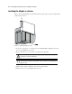
Attaching the Upgrade Module
The Compaq NC3134 Fast Ethernet Server Adapter design lets you attach an upgrade module.
This increases the number of RJ-45 ports to four, in addition to adding one 100 Mb/s FX fiber
port, one 1000 Mb/s fiber port, or one RJ-45 port that delivers 1000 Mb/s over twisted-pair
(Gigabit over copper) cabling.
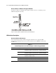
A Compaq Fast Ethernet or Gigabit upgrade module comes factory-assembled with a plastic
extension bracket (clamp) installed on the module. A kit packaged with each upgrade module
contains the following parts to attach the module to the adapter:
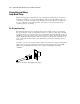
Two rivet assemblies — two hollow rivets and two flat-headed rivet pins
■
■
Read This First card — Instructions for attaching the upgrade module
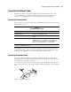
Removing the Adapter from a Server
If the adapter is already installed in a Compaq ProLiant server, you must first remove it to
install the upgrade module. If the adapter is not installed, go to the section titled “Installing the
Upgrade Module on the Adapter.”
NOTE: See the Compaq ProLiant PCI Hot Plug documentation for general information on removing the
adapter.
1. If the server is not PCI Hot Plug compliant, power down the server and unplug the power
cord.
2. Remove the server’s cover.
WARNING: To reduce the risk of personal injury from hot surfaces, allow the internal system
components to cool before touching them.
CAUTION: If the server is not PCI Hot Plug compliant, power it down and unplug the power
cord from the power outlet before removing the server cover. Failure to do so may damage the
adapter or server.
3. Remove the screw or clip holding the adapter in the server, then slide the adapter out of
the PCI slot.
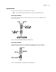
Installing the Upgrade Module on the Adapter
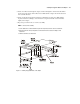
Follow these steps to install the upgrade module. Refer to Figure 2-1 for more information.
1. Remove any adhesive strip (provided for safety) that is sealing the option door on the
adapter.
2. Push and hold open the spring-loaded option door on the adapter.
3. Align the ports on the upgrade module with the option door opening, the two board-to-
board connectors on the upgrade module with the two board-to-board connectors on the
adapter, as well as the standoff (not included on all boards) on the upgrade module with
the hole in the adapter.
4. Gently but firmly press the connectors and the standoff (not included on all boards)
together until they are securely seated in each board.