
User`s guide

3-8 TL891 MiniLibrary System User's Guide
Compaq Confidential – Need to Know Required
Writer: Everett Godaire Project: TL891 MiniLibrary System User's Guide Comments:
Part Number: ER-TL891-UA.A01 File Name: d-ch3 Installation Last Saved On: 3/2/99 2:30 PM
Orientation of Parts During Assembly
To determine the orientation of an extension section, examine the flanges on
the edges of the section, and note that they are dissimilar. Position the section
so that its orientation matches that of the elevator base.
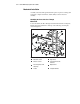
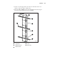
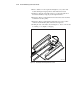
Figure 3-4 shows a typical pass-through mechanism assembly. The motor
drive section always goes on top, and the base section with the idler pulley
always goes on the bottom. Extension sections are mounted between the motor
drive section and the base section. All sections are joined together with tie
bars. For systems up to four modules, two support braces are needed, one
attached to the motor drive and one to the base section. For larger systems, a
third support brace should be mounted near the center of the pass-through
mechanism.
Preparing to Assemble the Pass-Through
Mechanism
You will need a clean, flat work area such as a table or work bench. The
surface should be long enough to support the full height of the pass-through
mechanism. The height is equal to the height of the stack of modules in your
system plus any gaps you intend to include in the stack. Use the following
procedure to assemble your pass-through mechanism.
Assembling the Pass-Through Mechanism
In most cases, you have received a pre-assembled pass-through mechanism. If
its length is correct for your system, turn to the section entitled Mechanical
Installation of the Expansion and Base Modules and continue on to the end of
the chapter. If you need to add sections, please take a few minutes to read this
section and the section entitled Installing the Belt, before proceeding to Adding
to an Existing Pass-Through Mechanism.
NOTE:
References to left and right refer to the position of the part when the pass-through
mechanism is assembled and mounted in the rack, as viewed from the front of the rack.
Refer to Figures 3-1 and 3-4.
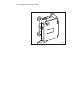
1. Place the base section, with the inside facing down, overhanging the
right end of the work area, with the bottom plate of the section toward
the right.
2. Place each of the extension sections, with the inside facing down, in a
row aligned edge-to-edge beginning with the base section. The bottoms
of the sections should be toward the right. Omit the motor drive at this
time.