Netelligent 1016 10Base-T Repeater User Guide
. . . . . . . . . . . . . . . . . . . . . . . . . . . . . NOTICE The information in this publication is subject to change without notice. COMPAQ COMPUTER CORPORATION SHALL NOT BE LIABLE FOR TECHNICAL OR EDITORIAL ERRORS OR OMISSIONS CONTAINED HEREIN, NOR FOR INCIDENTAL OR CONSEQUENTIAL DAMAGES RESULTING FROM THE FURNISHING, PERFORMANCE, OR USE OF THIS MATERIAL. This publication contains information protected by copyright.
. . . . . . . . . . . . . . . . . . . . . . . . . . . . . v Federal Communications Commission Notice Part 15 of the Federal Communications Commission (FCC) Rules and Regulations has established Radio Frequency (RF) emission limits to provide an interference-free radio frequency spectrum. Many electronic devices, including computers, generate RF energy incidental to their intended function and are, therefore, covered by these rules.
. . . . . . . . . . . . . . . . . . . . . . . . . . . . . . vi Federal Communications Commission Notice Modifications The FCC requires the user to be notified that any changes or modifications made to this device that are not expressly approved by Compaq Computer Corporation may void the user's authority to operate the equipment. Cables Connections to this device must be made with shielded cables with metallic RFI/EMI connector hoods in order to maintain compliance with FCC Rules and Regulations.
. . . . . . . . . . . . . . . . . . . . . . . . . . . . . vii Euopean Union (EU) Notice Products with the CE Marking comply with both the EMC Directive (89/336/EEC) and the Low Voltage Directive (73/23/EEC) issued by the Commission of the European Community.
. . . . . . . . . . . . . . . . . . . . . . . . . . . . . . viii Federal Communications Commission Notice Fiber Port Class 1 Classification Compaq fiber ports have been tested in accordance with the IEC 825-1 test standard and found to meet the Class 1, intrinsically eye-safe emitter classification. Product Label .
. . . . . . . . . . . . . . . . . . . . . . . . . . . . . 1-1 Chapter 1 Overview The Compaq Netelligent 1016 10Base-T unmanaged repeater is the ideal connectivity solution for departmental Ethernet workgroups. It is easy to configure, maintain, and expand and is capable of port management via its built-in LED indicators.
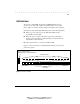
. . . . . . . . . . . . . . . . . . . . . . . . . . . . . . 1-2 Overview Figure 1-1 shows the repeater's front and back panels and the locations of the various repeater components: Power/Activity/Collision Media Expansion Port LEDs Media Expansion Port PWR 1 2 3 RJ-45 Ports and LEDs 4 5 6 7 8 9 10 11 12 14 13 15 16 UPLINK ACT MDI COL MDI-X MEP Power Cord Connector UPLINK Switch (for converting Port 16 to an uplinkable port) Back Panel Figure 1-1.
. . . . . . . . . . . . . . . . . . . . . . . . . . . . . 1-3 LED Indicators The repeater contains PWR, ACT, COL, and MEP LEDs that show the repeater's power status (ON or OFF), the incoming traffic on the repeater (heavy, light, or no activity), and the collision status (light or heavy activity). Each RJ-45 port has a Link Status LED that operates in the following manner: ■ When you power up the repeater, the Link Status LEDs are ON momentarily, then turn OFF.
. . . . . . . . . . . . . . . . . . . . . . . . . . . . . .
. . . . . . . . . . . . . . . . . . . . . . . . . . . . .
. . . . . . . . . . . . . . . . . . . . . . . . . . . . . 2-1 Chapter 2 Media Expansion Options The repeater contains a Media Expansion Port (MEP) that gives you the option of installing one of several Alternate Media Connectors (AMCs) to expand the network to other media. Each connector is sold separately. This chapter describes these connectors and how to install each.
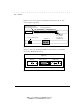
. . . . . . . . . . . . . . . . . . . . . . . . . . . . . . 2-2 Media Expansion Options IMPORTANT: If there is no connection or external terminator at the BNC port, set the jumper to the OFF position. Otherwise, excessive collisions will occur and adversely affect network performance. The AW1 jumper settings are shown in Figure 2-2: ON AW1 BNC Disabled OFF BNC Enabled (Default) Figure 2-2. AW1 Jumper Settings To install a BNC connector, follow these steps: 1.
. . . . . . . . . . . . . . . . . . . . . . . . . . . . . 2-3 4. Insert the BNC connector through the MEP opening and carefully push the 20-pin plug into the outlet on the repeater board until the AMC is secure. 5. Tighten the screws on the faceplate. 6. Restart the repeater. For information about starting the repeater, see the section “Connecting Power” in Chapter 3 of this guide.
. . . . . . . . . . . . . . . . . . . . . . . . . . . . . 3-1 Chapter 3 Setting Up the Repeater This chapter describes the requirements for setting up the repeater, including environmental, electrical, and spatial requirements, as well as UTP cabling considerations. The chapter also explains how to rack mount and power up the repeater, how to make a basic repeater-to-workstation connection, and how to set up some basic network configurations.
. . . . . . . . . . . . . . . . . . . . . . . . . . . . . . 3-2 Setting Up the Repeater Data communications equipment is sensitive to variations in voltage supplied by AC power supplies. Overvoltage, undervoltage, or transients can interfere with data integrity and may damage your equipment. CAUTION To protect against these voltage-related problems, power cables should be properly grounded and the following power management methods should be employed: • Use power protection devices.
. . . . . . . . . . . . . . . . . . . . . . . . . . . . . 3-3 3. To install the brackets in the repeater, insert the bracket clips into the bracket slots on the bottom of the repeater. The brackets rest flat against the bottom and the sides of the repeater, while the mounting holes that secure the bracket to the rack face the front of the repeater. To flushmount the repeater, use Slots 1 and 3 (see Figure 3-1). To have the repeater extend slightly out of the rack, use Slots 2 and 4. 4.
. . . . . . . . . . . . . . . . . . . . . . . . . . . . . . 3-4 Setting Up the Repeater 2. To remove a bracket from the repeater, pull the bracket forward until it unsnaps from the plastic ridge inside the mounting slot. Connecting Power To connect the repeater to power, follow these steps: 1. Plug the female IEC connector of the power cord into the power cord outlet on the back of the repeater. 2.
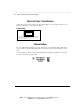
. . . . . . . . . . . . . . . . . . . . . . . . . . . . . 3-5 Do Remove the Power Plug from the Grounded Power Source Don’t Figure 3-2. Properly Disconnecting Power Cabling Considerations This section outlines twisted-pair wire specifications and describes how to make a simple direct connection between a repeater and a workstation. Twisted-Pair Wire Specifications The twisted-pair wiring must meet the following minimum specifications and requirements to ensure long-term LAN reliability.
. . . . . . . . . . . . . . . . . . . . . . . . . . . . . . 3-6 Setting Up the Repeater ❏ Nominal attenuation: Less than 11.5db ❏ Wire gauge between 18 and 26 AWG ■ Maximum distance requirement 328 feet (100 meters). This distance must include all cross-connect wire, wire in the walls, and any drop cables from wall plates to workstations (see the next section to determine the proper length). Maximum distances may be less for UTP cable run underground, in conduit, or in large cable bundles.
. . . . . . . . . . . . . . . . . . . . . . . . . . . . . 3-7 Brown-White White-Brown Green-White Blue-White White-Blue White-Green Orange-White White-Orange 8 7 6 5 4 3 2 1 1 2 3 4 5 6 7 8 White-Orange Orange-White White-Green White-Blue Blue-White Green-White White-Brown Brown-White Figure 3-3. D-Inside Wire The cable in Figure 3-4 shows how the wire connected to Pin 1 must be twisted with the wire connected to Pin 2, and the wire connected to Pin 3 must be twisted with the wire connected to Pin 6.
. . . . . . . . . . . . . . . . . . . . . . . . . . . . . . 3-8 Setting Up the Repeater Repeater-to-Workstation Connection To connect the repeater to a workstation, follow these steps: 1. Plug one end of the modular cord into a 10Base-T-equipped workstation. 2. Plug the other end of the modular cord directly into the desired port on the repeater, as shown in Figure 3-5. The maximum end-to-end cable distance is 328 feet (100 meters).
. . . . . . . . . . . . . . . . . . . . . . . . . . . . . 3-9 Setting the Uplink Switch The uplink switch on the front panel of the repeater converts Port 16 to an uplinkable port. This feature allows the repeater to connect to another repeater in a star topology. The default setting for the uplink switch is MDI-X (the standard RJ-45 port). The uplink switch helps simplify twisted-pair wiring between repeaters. Typically, the repeater's RJ-45 jacks function as input ports for workstation connections.
. . . . . . . . . . . . . . . . . . . . . . . . . . . . . . 3-10 Setting Up the Repeater Sample Network Configurations The following figures represent network configurations for a repeater LAN. Single Repeater Configuration Figure 3-7 shows one repeater connected to network stations within a 328 foot (100 meter) radius. You can place the repeater in a wiring closet or next to network stations. In this example, Port 16 of the repeater is configured as an input port to accommodate a workstation connection.
. . . . . . . . . . . . . . . . . . . . . . . . . . . . . 3-11 Repeater A (Primary Repeater to which Repeaters B and C are uplinked)) Repeater C Repeater B UPLINK SWITCH (MDI Position) Figure 3-9. Multiple-Repeater Connection Compaq Netelligent 1016 10Base-T Unmanaged Repeater User Guide Writer: Liz Fischer Project: Setting Up the Repeater Comments: 268749-001 File Name:749_3.
. . . . . . . . . . . . . . . . . . . . . . . . . . . . . . 3-12 Setting Up the Repeater Maximum Repeater Path Model Ethernet limits the total number of repeaters that can be in the path between any two nodes (workstations and servers). Up to four repeaters can exist between two nodes. Figure 3-10 shows an example of the maximum repeater path and the maximum number of connections in that path.
. . . . . . . . . . . . . . . . . . . . . . . . . . . . . A-1 Appendix A Technical Specifications This appendix describes the technical specifications for the repeater.
. . . . . . . . . . . . . . . . . . . . . . . . . . . . . . A-2 Technical Specifications Power Requirements ■ 100 to 240 VAC, 50 to 60 Hz ■ Power Consumption: ❏ Typical: 7W ❏ Maximum: 11W Environmental Specifications Operating Environment ■ 32° to 120° F; 0° to 49° C ■ 5% to 95% humidity (non-condensing) Storage Environment ■ 32° to 151° F; 0° to 66° C ■ 5% to 95% humidity (non-condensing) ■ 0 to 30,000 feet altitude; 0 to 9 kilometers ■ Convection Cooling Physical Specifications ■ 1.
. . . . . . . . . . . . . . . . . . . . . . . . . . . . . G-1 Glossary 10Base-2 An IEEE Standard (802.3) for local area networks. Complying networks must be able to carry information at a rate of 10 Mb/s over distances up to 606 feet (185 meters) of thin coaxial cable. 10Base-5 An IEEE Standard (802.3) for local area networks. Complying networks must be capable of carrying information at a rate of 10 Mb/s over distances up 1640 feet (500 meters) of thick coaxial cable. 10Base-T An IEEE Standard (802.
. . . . . . . . . . . . . . . . . . . . . . . . . . . . . . G-2 Glossary Backplane The data bus connections that interconnects different communication modules inside a network concentrator. BNC A thin Ethernet coax connector. Bridged Tap (Stub) A cable (or cord) connected to another cable (or cord) at a point other than its end. Such a tap causes impairment of network signal transmissions. Carrier Sense The monitoring of a local area network by a node to determine if another node is transmitting.
. . . . . . . . . . . . . . . . . . . . . . . . . . . . . G-3 Ethernet Transceiver A device used in an Ethernet local area network that couples data terminal equipment to other transmission media. Fiber Adapter A hardware device that converts System 4000 network signals between electrical signals on twistedpair wire and light pulses transmitted on fiber optic cable. Fiber Optic Cable A transmission medium consisting of a core of glass surrounded by strengthening material and a protective jacket.
. . . . . . . . . . . . . . . . . . . . . . . . . . . . . . G-4 Glossary Network Interface Connector (NIC) A plug-in expansion board that enables computers to send and receive data through the network. Node A computer workstation or other device in a network. Plenum Cord A communications cord with fire-retardant insulation generally used in suspended ceilings and other places where air circulates back to the building's airconditioning system.
. . . . . . . . . . . . . . . . . . . . . . . . . . . . . I-1 Index F A Features 1-1 Fiber 1-1 Fiber connectors 2-3 Fiber installation 2-3 Flashing yellow LEDs 1-4 Frequency 3-1 Alternate Media Connectors See AMCs AMCs 2-3, A-1 illustration 2-1 part numbers 2-1 AUI 1-1, A-1 AUI installation 2-3 AW1 jumper 2-2 H Humidity A-2 I IEEE 802.
. . . . . . . . . . . . . . . . . . . . . . . . . . . . . .