Netelligent 1017A/B 10Base-T Hub User Guide ©1997 Compaq Computer Corporation. All rights reserved. Compaq Registered U.S. Patent and Trademark Office. Company and product names mentioned herein may be trademarks and/or registered copyright and trademarks of their respective companies.
. . . . . . . . . . . . . . . . . . . . . . . . . . . . . iii NOTICE The information in this publication is subject to change without notice. COMPAQ COMPUTER CORPORATION SHALL NOT BE LIABLE FOR TECHNICAL OR EDITORIAL ERRORS OR OMISSIONS CONTAINED HEREIN, NOR FOR INCIDENTAL OR CONSEQUENTIAL DAMAGES RESULTING FROM THE FURNISHING, PERFORMANCE, OR USE OF THIS MATERIAL. This publication contains information protected by copyright.
. . . . . . . . . . . . . . . . . . . . . . . . . . . . . . v Contents Chapter 1 Overview Features......................................................................................................................... 1-1 Chapter 2 Hardware Description Front Panel.................................................................................................................... 2-2 LED Indicator Panel ..............................................................................................
. . . . . . . . . . . . . . . . . . . . . . . . . . . . . . vi Using the AUI Port ................................................................................................ 4-5 Guidelines for Multiple Hub Configurations................................................................ 4-6 Appendix A Troubleshooting Diagnosing Hub Indicators .......................................................................................... A-1 System Diagnostics.................................................
. . . . . . . . . . . . . . . . . . . . . . . . . . . . . . vii Preface This user guide is designed for the experienced network installer. It covers the following information to help in the installation and operation of the Netelligent 1017A/B 10Base-T Hub: Q Hardware description and summary of features Q Hardware installation and configuration Q Troubleshooting tips Package Checklist Carefully unpack the contents of the package and verify them against the checklist given below.
. . . . . . . . . . . . . . . . . . . . . . . . . . . . . . 1-1 Chapter 1 Overview The Netelligent 1017A/B 10Base-T Hub is a 16-port Ethernet hub which features an on-board microprocessor designed to monitor network utilization, collisions, link and port partition status. The hub’s comprehensive LED indicator panel simplifies installation and network troubleshooting by showing network utilization and collision levels at the hub ports.
. . . . . . . . . . . . . . . . . . . . . . . . . . . . . . 2-1 Chapter 2 Hardware Description The 1017A/B 10Base-T Hub is a highly reliable network concentrator that complies with IEEE 802.3 specifications. By passing data signals received on any port to all other ports, without modification, this hub meets the requirements for both Ethernet and IEEE 802.3 networks. This chapter describes the main hub components.
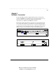
. . . . . . . . . . . . . . . . . . . . . . . . . . . . . . 2-2 Hardware Description Front Panel This section describes the 1017A/B hub’s front panel. LED Indicator Panel The LED indicator panel includes comprehensive indicators for monitoring device and network status. The LEDs on the front panel let you easily monitor the status of each port, plus the overall condition of the hub. The following sections describe the function of each indicator. Figure 2-3 .
. . . . . . . . . . . . . . . . . . . . . . . . . . . . . . 2-3 CPU Color: Green Label: CPU Function: Power indicator LED Activity Condition Indication BLINKING LIGHT ON CPU is running. NO LIGHT OFF CPU is not running. Utilization Label (%) Color 1% 5% 15% Green 30% 65+% Amber (yellow) Function Indicates percentage utilization of LAN bandwidth. The Utilization LEDs indicate the percentage of network bandwidth used by valid data. The hub updates this display every 0.5 seconds.
. . . . . . . . . . . . . . . . . . . . . . . . . . . . . . 2-4 Hardware Description Collision Label (%) Color Function 1% 3% 5% Green 10% 15+% Amber (yellow) Indicates the percentage of packet collisions occurring out of the total packets received by the hub. Collisions occur when two or more devices connected to a hub attempt to transmit data simultaneously on the network. When a collision occurs, devices pause and then re-transmit after a pseudo-random wait period.
. . . . . . . . . . . . . . . . . . . . . . . . . . . . . . 2-5 Port Status Indicators There are 18 pairs of port status LED indicators. Each pair consists of a Partition LED (top row) and Link/Traffic LED (bottom row). Each pair (or column) has a label referring to the port number the LEDs monitor. For example, the port status LED pairs labeled AUI and BNC monitor the AUI and BNC ports on the back panel. The other 16 pairs are for the RJ-45 ports on the front panel of the hub.
. . . . . . . . . . . . . . . . . . . . . . . . . . . . . . 2-6 Hardware Description Link The corresponding Link/Traffic LED lights when a device (for example, computer, hub or bridge) establishes a valid connection using the RJ-45 port. However, for the AUI and BNC ports, no link connection is tested. The Link/Traffic LED for these ports only monitor the traffic condition.
. . . . . . . . . . . . . . . . . . . . . . . . . . . . . . 2-7 Setting the Uplink Switch The uplink switch is located on the right side of the front panel beside Port 16. It enables or disables the uplink function of Port 16. When the switch is enabled, Port 16 functions as an uplink port for connecting to another compatible hub. When the switch is disabled, Port 16 functions as a normal station port for connecting to a workstation.
. . . . . . . . . . . . . . . . . . . . . . . . . . . . . . 2-8 Hardware Description Port Connections BNC Port (10BASE2) This hub has a built-in BNC transceiver for a connection using thin coaxial cable. The BNC port can link up to 30 hubs on a thin coaxial cable segment. The thin coaxial cable that links the BNC ports may be extended up to 185 meters and have computers or other Ethernet devices attached to it. When connecting two hubs via BNC ports, there should be at least 0.
. . . . . . . . . . . . . . . . . . . . . . . . . . . . . . 2-9 Power Switch The power switch is located at the right side of the back panel. It is used to power the hub on and off. Compaq Netelligent 1017A/B 10Base-T Hub User Guide Writer: Chris Seiter Project: Hardware Description Comments: File Name:1017A_2.
. . . . . . . . . . . . . . . . . . . . . . . . . . . . . . 3-1 Chapter 3 Installing the Hub This chapter describes how to install the 1017A/B 10Base-T Hub. It describes specific installation requirements, installation procedures, and basic network connections. Site Requirements Consider the following site requirements before you install the hub. Q Verify that the power source meets the following electrical specifications.
. . . . . . . . . . . . . . . . . . . . . . . . . . . . . . 3-2 Installing the Hub Connecting the Hub System Follow these steps to connect the hub to your network. 1. Cascade hubs using the uplink port (Port 16). You can convert RJ-45 port 16 to an uplink port to allow cascading to other 1017A/B or compatible hubs. The hub’s uplink switch reverses transmit and receive signals, which lets you use straight-through cable to cascade hubs instead of crossover cable.
. . . . . . . . . . . . . . . . . . . . . . . . . . . . . . 3-3 NOTE : If your transceiver provides an SQE (Signal Quality Error) test, then it must be disabled. 3. Connect workstations to the hub. Prepare the workstations you want to network. Be sure they have properly installed 10Base-T network interface cards, or external 10BaseT transceivers. Prepare straight-through twisted-pair cables with RJ-45 plugs at both ends. The length of each cable should not exceed 100 meters.
. . . . . . . . . . . . . . . . . . . . . . . . . . . . . . 3-4 Installing the Hub 5. Verify that all attached devices have a valid connection. The hub monitors link status for each port. If any device is properly connected to the hub and transmitting a link beat signal, the Link indicator lights for the corresponding port. If valid traffic is being transmitted by the connected device, the same indicator (now referred to as the Traffic indicator) flashes to indicate network activity.
. . . . . . . . . . . . . . . . . . . . . . . . . . . . . . 4-1 Chapter 4 Configurations The 1017A/B 10Base-T Hub allows flexibility in configuring your network. You can use the hub in a stand-alone or multiple hub configuration. The hub’s RJ-45 uplink port (Port 16) lets you cascade multiple hubs using Category 3, 4 or 5 unshielded twisted-pair cable, or you can connect multiple hubs through a backbone connection. You can install the 1017A/B hub in a standard wiring closet or in a workgroup.
. . . . . . . . . . . . . . . . . . . . . . . . . . . . . . 4-2 Configuring the Hub Connecting Multiple Hubs The following sections describe how to connect multiple hubs using the 1017A/B hub’s RJ-45 uplink port, crossover twisted-pair cable, and a backbone connection. Using the RJ-45 Uplink Port The 1017A/B hub provides an uplink port you can use to connect to another hub. You can convert Port 16 to an uplink port by sliding the uplink switch to the right (MDI) position.
. . . . . . . . . . . . . . . . . . . . . . . . . . . . . . 4-3 NOTE : When using the uplink port to connect to another hub, use straight-through (normal) twisted-pair cable. This cable is the same as that used for connecting the hub to a workstation. For more information, see Appendix B - Cable Pin Assignments. Using Crossover Twisted-Pair Cable With a crossover twisted-pair cable, you can connect the 1017A/B hub to a compatible hub using any available RJ-45 port.
. . . . . . . . . . . . . . . . . . . . . . . . . . . . . . 4-4 Configuring the Hub Backbone Connection There are two trunk ports on the back panel to enable AUI and BNC connections. You can use either type to link to an Ethernet backbone, depending on the media type required. Using the BNC Port The 1017A/B hub can be stacked with other hubs using the BNC port on the back panel. Through this port, you can connect hubs via thin coaxial cable (10Base2).
. . . . . . . . . . . . . . . . . . . . . . . . . . . . . . 4-5 Using the AUI Port To connect to Thick Ethernet, attach a 10Base5 transceiver to the backbone, and run an AUI drop cable between the the hub and the transceiver. A Thick Ethernet segment can run up to 500 meters and connect up to 100 nodes. However, an Ethernet trunk can contain no more than three coaxial segments (10Base2 or 10Base5) if each segment extends up to the maximum length (allowed for Thin or Thick Ethernet).
. . . . . . . . . . . . . . . . . . . . . . . . . . . . . . 4-6 Configuring the Hub Guidelines for Multiple Hub Configurations In a multiple hub configuration, the maximum limit between any two workstations is five cable segments and four hubs based on IEEE 802.3 recommendations. For example, Figure 4-6 shows that if Workstation A sends a message to Workstation B, there can only be up to four hubs in the path between them.
. . . . . . . . . . . . . . . . . . . . . . . . . . . . . . A-1 Appendix A Troubleshooting Diagnosing Hub Indicators You can easily monitor the 1017A/B 10Base-T Hub using its comprehensive panel indicators. These indicators help you identify problems the hub may encounter. This section describes common problems and possible solutions. Symptom: CPU indicator displays a steady green light long after power on. Cause: Defective CPU Solution: Have the hub’s CPU replaced. Ask for dealer assistance.
. . . . . . . . . . . . . . . . . . . . . . . . . . . . . . A-2 Appendix A: Troubleshooting System Diagnostics Installation Verify that all system components have been properly installed. If one or more components appear to be malfunctioning, test them in an alternate environment where all the other components are functioning properly. Cabling 1. Verify that the cabling type is correct. Be sure all cable connectors are securely seated in the required ports.
. . . . . . . . . . . . . . . . . . . . . . . . . . . . . . A-3 Hub Integrity As a last resort verify the hub’s integrity with a power-on reset. Turn the power to the hub off and then on. If the problem still persists and you have completed all the preceding diagnoses, then contact your Compaq Authorized Reseller for further assistance. Compaq Netelligent 1017A/B 10Base-T Hub User Guide Writer: Chris Seiter Project: Appendix A: Troubleshooting Comments: File Name:1017A_A.
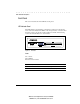
. . . . . . . . . . . . . . . . . . . . . . . . . . . . . . B-1 Appendix B Port and Cable Assignments Figure B-1 . RJ-45 Connector (on the Hub Side) Pin Assignment (Port 1 ~ 16) Assignment (Daisy-Chain Port) 1 Input Receive Data + Output Transmit Data + 2 Input Receive Data - Output Transmit Data - 3 Output Transmit Data + Input Receive Data + 6 Output Transmit Data - Input Receive Data - 4, 5, 7, 8 Not Used Not Used Table B-1 .
. . . . . . . . . . . . . . . . . . . . . . . . . . . . . . B-2 Appendix B: Port and Cable Assignments AUI Port The following table shows pin assignments for the AUI port. Pin Assignment 1 Collision In Shield 2 Collision In + 3 Data Out + 4 Data In Shield 5 Data In + 6 DC Power Common 9 Collision In - 10 Data Out - 11 Data Out Shield 12 Data In - 13 DC Power + 14 Power Shield 7, 8 ,15 No Connection Table B-2 .
. . . . . . . . . . . . . . . . . . . . . . . . . . . . . . C-1 Appendix C Specifications Product Specifications Transmission Technique Access Method Standards Conformance Media Supported Interfaces Dimensions Power Requirements Temperature Humidity Certification Emissions Immunity Safety Baseband CSMA/CD, 10 Mb/s IEEE 802.
. . . . . . . . . . . . . . . . . . . . . . . . . . . . . . D-1 Appendix D Regulatory Standards Compliance EMI Warning FCC Class A Certification Compaq Computer Corporation Model Number: 1017A/B This device complies with Part 15 of the FCC Rules. Operation is subject to the following conditions: 1. This device may not cause harmful interference, and 2. This device must accept any interference received, including interference that may cause undesired operation.
. . . . . . . . . . . . . . . . . . . . . . . . . . . . . . D-2 Appendix D: Regulatory Standards Compliance You may use unshielded twisted-pair (UTP) for RJ-45 connections. However, use only shielded cable to connect I/O devices to this equipment via BNC connection. Warning: • Wear an anti-static wrist strap or take other suitable measures to prevent electrostatic discharge whenever handling this equipment.
. . . . . . . . . . . . . . . . . . . . . . . . . . . . . . I-1 connection 2-8 devices 2-8 segment 2-8 trunk 3-2, 4-4, 4-5 Index A F AUI attaching 3-2 drop cable 2-8, 3-2, 4-5 port 1-1, 2-8, 3-2, 4-5 port connection 4-5 AUI/BNC backbone ports 2-4 Automatic partitioning 1-1 Automatic polarity detection 1-1 FCC standards 3-2 Fiber-optic cabling 1-1, 3-2 connection 2-8 Ethernet cable 2-8 B IEEE 802.
. . . . . . . . . . . . . . . . . . . . . . . . . . . . . .
©1997 Compaq Computer Corporation. All rights reserved. Compaq Registered U.S. Patent and Trademark Office. Company and product names mentioned herein may be trademarks and/or registered copyright and trademarks of their respective companies.