Netelligent 1124 100Base-TX Repeater User Guide
. . . . . . . . . . . . . . . . . . . . . . . . . . . . . iii NOTICE The information in this publication is subject to change without notice. COMPAQ COMPUTER CORPORATION SHALL NOT BE LIABLE FOR TECHNICAL OR EDITORIAL ERRORS OR OMISSIONS CONTAINED HEREIN, NOR FOR INCIDENTAL OR CONSEQUENTIAL DAMAGES RESULTING FROM THE FURNISHING, PERFORMANCE, OR USE OF THIS MATERIAL. This publication contains information protected by copyright.
. . . . . . . . . . . . . . . . . . . . . . . . . . . . . v Federal Communications Commission Notice This equipment has been tested and found to comply with the limits for a Class A digital device, pursuant to Part 15 of the FCC Rules. These limits are designed to provide reasonable protection against harmful interference when the equipment is operated in a commercial environment.
. . . . . . . . . . . . . . . . . . . . . . . . . . . . . vi European Union Notice Products with the CE (Community European) Marking comply with both the EMC Directive (89/336/EEC) and the Low Voltage Directive (73/23/EEC) issued by the Commission of the European Community.
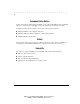
. . . . . . . . . . . . . . . . . . . . . . . . . . . . . . vii Contents Preface Intended Reader........................................................................................................ix Organization of Contents ..........................................................................................ix Chapter 1 Introduction Features ..................................................................................................................1-1 Package Contents.......................
. . . . . . . . . . . . . . . . . . . . . . . . . . . . . viii Setting the Uplink Switches ....................................................................................3-3 Interconnecting Repeaters.......................................................................................3-4 Connecting Power...................................................................................................3-5 Disconnecting Power..............................................................................
. . . . . . . . . . . . . . . . . . . . . . . . . . . . . . ix Preface This guide includes information about how to install and operate the Compaq Netelligent 1124 100Base-TX Repeater. We recommend that you read all chapters in this guide to become familiar with all of the repeater's features and to ensure a successful installation. Intended Reader This guide is written for network administrators and technicians responsible for hardware installation.
. . . . . . . . . . . . . . . . . . . . . . . . . . . . . . 1-1 Chapter 1 Introduction Compaq’s Netelligent 1124 100Base-TX Repeater provides functionality for 24 RJ-45 ports. The repeater's uplink capability lets you connect the repeater to another repeater or other 100Base-TX repeater. For backup power, you can install an optional redundant power supply. The repeater's front panel makes it easy to view the current operating status.
. . . . . . . . . . . . . . . . . . . . . . . . . . . . .
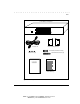
. . . . . . . . . . . . . . . . . . . . . . . . . . . . . . 1-3 1124 100Base-TX Repeater 13 14 15 16 17 18 1 2 3 4 5 6 19 20 21 22 23 24 8 9 10 11 12 MDI-X 7 PWR A PWR B MDI COL MDI-X MDI-X Power Cord Rack-Mounting Brackets 1/2-inch Rack Mount Screws (4) Rubber Feet (4) 3/8-inch Bracket Screws (8) Limited Warranty Compaq Netelligent 1124 100Base-TX Repeater User Guide Limited Warranty User Guide Figure 1-1.
. . . . . . . . . . . . . . . . . . . . . . . . . . . . . 1-4 Introduction Operational Overview This section provides an overview of the repeater's components, which include the LED indicators, RJ-45 ports, and uplink ports, and discusses the basic functionality of the repeater. Figures 1-2 and 1-3 show the repeater's front and back panel.
. . . . . . . . . . . . . . . . . . . . . . . . . . . . . . 1-5 LED Indicators The repeater features several LED indicators that help you monitor the repeater's status. ■ The LEDs on the left side of the front panel show the status of the power supplies as well as the 100Base-TX collision status. ■ The LEDs above the RJ-45 ports indicate the link, activity, and partition status for each of the ports. Figure 1-4 shows the LED arrangement for the repeater; Table 4-1 describes the functions of the LEDs.
. . . . . . . . . . . . . . . . . . . . . . . . . . . . . . 2-1 Chapter 2 Planning Repeater Installation This chapter contains installation requirements and system planning charts that will help you prepare for installing the repeater. Installation Requirements To help ensure a correct installation, read this section to determine the environmental, electrical, spatial, and cable requirements.
. . . . . . . . . . . . . . . . . . . . . . . . . . . . . 2-2 Planning Repeater Installation CAUTION: The power outlet must be a non-switched, three-pronged, grounded outlet. Do not use a three-to-two pronged adapter at the outlet. Doing so may result in electrical shock and/or damage to the repeater and will void your warranty. NOTE: If the supplied power cord is lost or damaged, replace it with a power cord of the same type and current rating (10 A).
. . . . . . . . . . . . . . . . . . . . . . . . . . . . . . 2-3 Solid copper ■ Installing New Wire If you are installing the repeater where no wiring is present, or if existing wiring does not meet the above specifications, install new wiring. The new wiring should conform to national and local electrical wiring code requirements and meet the above specifications. When installing wire, it is a good idea to install extra pairs of wire for future expansion.
. . . . . . . . . . . . . . . . . . . . . . . . . . . . .
. . . . . . . . . . . . . . . . . . . . . . . . . . . . . . 2-5 System Planning Charts The charts in Figures 2-2 and 2-3 provide a convenient way of planning the connections for your repeater. 100Base-TX Repeater Setup and Cabling Chart Date Unit Number Port Building Connects To 1 Location 2 3 4 Rack Mount 5 Table 6 Uplink Switch Setting 7 8 MDI-X (default) MDI (uplinkable) 9 10 11 12 13 14 15 16 17 18 19 20 21 22 23 24 Figure 2-2.
. . . . . . . . . . . . . . . . . . . . . . . . . . . . . 2-6 Planning Repeater Installation Rack Inventory Chart Use this chart to record the components installed in a particular rack. Date Wiring Closet Number Rack Number Installer Example 100Base-TX Repeater 100Base-TX Repeater Figure 2-3. Rack Inventory Chart Writer: Chris Seiter Project: Planning Repeater Installation Comments: 185810-001/707119-001 File Name:10024_2.
. . . . . . . . . . . . . . . . . . . . . . . . . . . . . . 3-1 Chapter 3 Installing the Repeater This chapter explains how to mount the repeater, attach cables, and interconnect the repeater to a second repeater. Mounting the Repeater You can place the repeater on a level surface (table top or shelf, for example) or mount it in a standard EIA 19-inch rack.
. . . . . . . . . . . . . . . . . . . . . . . . . . . . . 3-2 Installing the Repeater 1. Remove the two screws from the left and right side of the repeater. (These screws are extras and are not needed to install the mounting brackets.) 2. Position the bracket as shown in Figure 3-1, and secure it with the smaller bracket screws. Then attach the remaining bracket to the other side of the repeater. Bracket Screws 21 22 23 24 9 10 11 12 MDI MDI-X Figure 3-1. Attaching the Mounting Brackets 3.
. . . . . . . . . . . . . . . . . . . . . . . . . . . . . . 3-3 Connecting Twisted-Pair Cable Each RJ-45 port on the repeater can accept a standard 8-wire twisted-pair (UTP) cable that ends with an RJ-45 connector. These ports can support cable lengths up to 328 feet (100 meters). To attach twisted-pair cable, plug one of the RJ-45 connectors into the selected port on the repeater. Connect the other RJ-45 connector into a 100Base-TX or 10Base-T workstation.
. . . . . . . . . . . . . . . . . . . . . . . . . . . . . 3-4 Installing the Repeater The default setting for the uplink switches is MDI-X (Media Dependent Interface-Reversed, that is, a standard IN repeater port). To convert Port 1 or Port 12 to an uplinkable OUT port, use a small, slotted screwdriver, or a similar tool, to set the switch to the MDI position (Figure 34). NOTE: IEEE specifications allow only one 100 Mb/s uplink connection per collision domain.
. . . . . . . . . . . . . . . . . . . . . . . . . . . . . . 3-5 To convert Port 1 or Port 12 to an uplinkable OUT port, use a small, slotted screwdriver, or a similar tool, to set the switch to the MDI-X position 13 14 15 16 17 18 1 2 3 4 5 6 19 20 21 22 23 24 8 9 10 11 12 MDI-X 7 PWR A PWR B COL MDI MDI-X MDI MDI-X MDI-X 13 14 15 16 17 18 1 2 3 4 5 6 19 20 21 22 23 24 8 9 10 11 12 MDI-X 7 PWR A PWR B COL MDI-X MDI MDI-X Figure 3-5.
. . . . . . . . . . . . . . . . . . . . . . . . . . . . . 3-6 Installing the Repeater PWR B PWR A Female Power Cable Connector Figure 3-5. Connecting the Power Cable WARNING: The repeater has no power switch. Connecting the repeater to the power source via the power cable’s three-pronged plug powers up the repeater 2. Insert the three-pronged plug on the power cable into a non-switched, grounded power outlet on a wall, a power strip, or a grounded extension cord.
. . . . . . . . . . . . . . . . . . . . . . . . . . . . . . 3-7 Disconnecting Power To power down the repeater, disconnect the power cord from the nonswitched, grounded power outlet on the wall, power strip, or grounded extension cord. The power cord is not a TUV-tested disconnect. Therefore do not power down the repeater by disconnecting the power cord connector from the back of the repeater. Replacing the Power Supply The power supply's modular design makes the supply easy to replace.
. . . . . . . . . . . . . . . . . . . . . . . . . . . . . 3-8 Installing the Repeater PWR A PWR B Redundant Power Supply Module Spring Screws Figure 3-6. Installing a Redundant Power Module 4. Plug the power cord into the connector on the new power supply module. 5. Insert the power cord’s three-pronged plug into a non-switched, grounded power outlet on a wall, a power strip, or a grounded extension cord.
. . . . . . . . . . . . . . . . . . . . . . . . . . . . . . A-1 Appendix A Specifications Electrical Specifications Ports and Connectors ■ 24 shielded RJ-45 repeater ports for 100Base-TX ❏ Port 12 100Base-TX uplink port with MDI/MDI-X option LED Indicators ■ Power (PWR A and PWR B) and Collision (COL) ■ 24 RJ-45 port LEDs to indicate 100Base-TX status ■ One two-position (MDI/MDI-X) uplink switch for uplink port Controls Power Requirements ■ Voltage: 100 to 240 VAC ■ Power: 1.5 to 0.
. . . . . . . . . . . . . . . . . . . . . . . . . . . . . A-2 Specifications Power Supply ■ 90W (autosensing) ❏ +5 VDC at 14 Amps; +12 VDC at 2 Amps (no minimum load required) Physical Specifications Dimensions ■ 3 x 16.95 x 14 inches, 7.6 x 43 x 33.6 cm (HxWxD) ■ 9.9 pounds (4.
. . . . . . . . . . . . . . . . . . . . . . . . . . . . . . I-1 M Index A Air circulation requirements 2-2 Amps 2-1 C Cable 3-5 Cable distance, maximum 3-4 Charts, planning 2-5 Class II support 1-1 Collision domain 3-4 Crossover cables 3-3 D Default, uplink 3-3 E Electrical requirements 2-1 Environmental requirements 2-1 H Hz 2-1 I IEEE 802.
. . . . . . . . . . . . . . . . . . . . . . . . . . . . . . I-2 Index RJ-45 ports 1-1, 1-4, 1-7 S Segment 1-7, 3-3 T Twisted pair crossover 2-4 straight through 2-4 Twisted-pair wiring 2-2 U Uplink port 1-1 Uplink switch 1-7, 3-3 UTP 1-7, 2-2, 3-3 V VAC 2-1 W Wire gauge 2-2 Wiring requirements 2-2 Wiring, new 2-3 Writer: Liz Fischer Project: Index Comments: File Name:10024_I.