b Getting Started Compaq Notebook Series Document Part Number: 355449-001 August 2004 This guide explains how to set up your hardware and software and begin using your notebook.
© Copyright 2004 Hewlett-Packard Development Company, L.P. Microsoft and Windows are U.S. registered trademarks of Microsoft Corporation. SD Logo is a trademark of its proprietor. Bluetooth is a trademark owned by its proprietor and used by Hewlett-Packard Company under license. Adobe and Acrobat are trademarks of Adobe Systems Incorporated. The information contained herein is subject to change without notice.
Contents 1 Hardware Setup Step 1: Identify the Setup Hardware . . . . . . . . . . . . . . . . Step 2: Insert the Battery Pack . . . . . . . . . . . . . . . . . . . . . Step 3: Connect the Modem. . . . . . . . . . . . . . . . . . . . . . . Step 4: Connect the Notebook to External Power . . . . . . Step 5: Open the Notebook . . . . . . . . . . . . . . . . . . . . . . . Step 6: Turn On the Notebook . . . . . . . . . . . . . . . . . . . . . 1–2 1–3 1–4 1–7 1–8 1–9 2 Software Setup Welcome to Windows . . . . .
Contents Connect to the Internet . . . . . . . . . . . . . . . . . . . . . . . . . . . 3–8 Enable Communication Hardware. . . . . . . . . . . . . . . 3–8 Set Up Internet Service . . . . . . . . . . . . . . . . . . . . . . . 3–9 Preview the Help and Support Guide. . . . . . . . . . . . . . . 3–11 4 Notebook Tour Top Components . . . . . . . . . . . . . . . . . . . . . . . . . . . . . . . 4–2 Keys . . . . . . . . . . . . . . . . . . . . . . . . . . . . . . . . . . . . . . 4–2 TouchPad . . . . . . . . . . .
1 Hardware Setup During hardware setup, you will 1. Identify the hardware you need to set up the notebook. 2. Insert the battery pack into the notebook, so the battery can begin to charge as soon as the notebook is connected to external power. 3. Connect the modem, so you will be able to register the notebook and operating system during software setup. 4. Connect the notebook to external power. 5. Open the notebook. 6. Turn on the notebook.
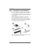
Hardware Setup Step 1: Identify the Setup Hardware To set up the notebook for the first time, you need the notebook, the AC adapter 1, the power cord 2, and the battery pack 3. If you would like to use the modem to register your notebook and operating system during software setup, you will also need the modem cable 4. If you are connecting the modem cable in a country where RJ-11 telephone jacks are not standard, you will need the modem adapter 5 to connect the modem cable.
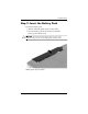
Hardware Setup Step 2: Insert the Battery Pack To insert the battery pack: 1. Turn the notebook upside down on a flat surface. 2. Pivot the battery pack into the battery bay until the battery pack is firmly seated. Ä CAUTION: To prevent a lack of response when you turn on the notebook at step 5, make sure the battery pack is firmly seated. (Battery packs vary by model.
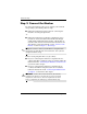
Hardware Setup Step 3: Connect the Modem To connect the modem so that you can register your notebook and operating system during software setup: ■ Follow the instructions in this section for connecting the modem to an analog telephone line. -or■ Follow the instructions provided by your Internet service provider to connect the notebook to the Internet through a DSL (Digital Subscriber Line) modem, cable modem, or network connection.
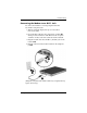
Hardware Setup Connecting the Modem to an RJ-11 Jack To connect the modem to an analog telephone line that has an RJ-11 telephone jack: 1. Turn the notebook display-side up on a flat surface near an AC outlet. 2. If your modem cable has noise suppression circuitry 1, which prevents interference with TV and radio reception, orient the circuitry end of the cable toward the notebook. 3. Plug the modem cable into the RJ-11 (modem) jack on the notebook 2. 4.
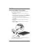
Hardware Setup Connecting the Modem with an Adapter To connect the modem to an analog telephone line that does not have an RJ-11 telephone jack: 1. Turn the notebook display-side up on a flat surface near an AC outlet. 2. If the modem cable has noise suppression circuitry 1, which prevents interference with TV and radio reception, orient the circuitry end of the cable toward the notebook. 3. Plug the modem cable into the RJ-11 (modem) jack on the notebook 2. 4.
Hardware Setup Step 4: Connect the Notebook to External Power To connect the notebook to external AC power: 1. Plug the AC adapter cable into the power connector 1. (The power connector is on the rear of the notebook.) 2. Plug the power cord into the AC adapter 2, and then into an AC outlet 3. When the notebook receives AC power, the battery pack begins to charge and the battery light 4 (on the front of the notebook) is turned on. When the battery pack is fully charged, the battery light is turned off.
Hardware Setup Step 5: Open the Notebook To open the notebook: 1. Press the display release button 1 to release the display. 2. Raise the display 2.
Hardware Setup Step 6: Turn On the Notebook » To turn on the notebook, press the power button 1. The power button light 2 and the power/standby light 3 are turned on, and you are prompted to begin software setup. power button light and the power/standby light display ✎ The the same information. The power button light is visible only when the notebook is open; the power/standby light is visible when the notebook is closed.
2 Software Setup During software setup you can ■ Select regional preferences. ■ Accept license agreements. ■ Name your notebook. ■ Register online. ■ Create user accounts. If you prefer not to register your notebook during software setup, you can do so at any time after software setup is complete. You can also change or add any settings you select or skip during the setup process.
Software Setup Welcome to Windows The first window in software setup is Welcome to Microsoft® Windows®. This window welcomes you to your Microsoft Windows operating system and introduces you to software setup navigation: ■ To display additional information about the text in any setup window, select the question mark icon in the lower right-hand section of the window or press the f1 key on your keyboard.
Software Setup Select Your Regional Preferences The next 2 windows prompt you to confirm or select regional preferences. Regional preferences are preset for the country in which you purchased the notebook. ■ Dates and currency window—The operating system will use the region and language preferences you confirm or select in the How should dates and currency appear? window to format dates and currency. Notice that some languages have regional versions.
Software Setup Name Your Notebook If you plan to include your notebook on a home network, your notebook must have a unique name. In the What’s your computer’s name? window, you can retain the default name shown in the Computer name text field or choose another name. For example, you might want to base your notebook name on a person’s name, “David,” or a location, “Familyroom.” In order for your notebook name to be displayed on a network, the name ■ Must be no longer than 15 characters.
Software Setup If you connected your modem during the “Step 3: Connect the Modem” section in Chapter 1, “Hardware Setup,” or have connected the notebook to the Internet by another method, the Connecting to online registration window is displayed. This window describes the progress of your registration. If you are unable to send your registration, you can do so at any time after software setup is complete.
3 Next Steps Enable TouchPad Tapping TouchPad Tapping is a TouchPad preference that enables you to tap the TouchPad once to select an item or twice to double-click an item. You might want to use this feature as you begin to use your notebook software. To determine whether TouchPad Tapping is enabled on your notebook, or to enable or disable this feature: 1. Use the TouchPad to select Start > Control Panel > Printers and Other Hardware > Mouse > Device Settings. Then select the Settings button. 2.
Next Steps Protect Your Notebook You can use the information in this section to ■ Protect your notebook from viruses. ■ Protect your notebook from power surges. ■ Protect your system files. ■ Protect your privacy. ■ Use your notebook safely. ■ Turn off your notebook properly.
Next Steps Protect Your System Files System Restore is an operating system feature that enables you to undo harmful changes to your notebook software by restoring your software to an earlier time, called a restore point, when your software was functioning optimally. Restore points are restorable, benchmark “snapshots” of your application, driver, and operating system files.
Next Steps Protect Your Privacy When you use the notebook for email, network, or Internet access, it is possible for unauthorized persons to obtain information about your notebook and the data it contains. (For Internet access instructions see the “Connect to the Internet” section later in this chapter.) To optimize the privacy protection features included with your notebook, it is recommended that you ■ Keep your operating system updated. Many Windows updates contain security enhancements.
Next Steps Under some circumstances a firewall can block access to Internet games, interfere with printer or file sharing on a network, or block authorized email attachments. To temporarily solve the problem, disable the firewall, perform the task, and then reenable the firewall. To permanently resolve the problem, reconfigure the firewall. ■ If you are using Internet Connection Firewall, select Start > Help and Support for configuration information or to contact a support specialist.
Next Steps Use the Notebook Safely This equipment has been tested and found to comply with the limits for a Class B digital device, pursuant to Part 15 of the FCC Rules. For more safety and regulatory information refer to Regulatory and Safety Notices on the Documentation CD and to the printed Wireless Regulatory Notices document included with your notebook.
Next Steps Turn Off the Notebook Properly Whenever possible, turn off the notebook by using the standard Windows shutdown procedure for your operating system: ■ In Windows XP Home, select Start > Turn Off Computer > Turn Off. ■ In Windows XP Professional, select Start > Turn Off Computer > Shut Down, and then select OK. (If you connect your notebook to a network domain, the name of the Turn Off Computer button might change to Shut Down.
Next Steps Connect to the Internet To connect the notebook to the Internet, you must enable your communication hardware and have an account with an Internet service provider (ISP). Enable Communication Hardware Your modem is enabled when the modem cable is connected to the notebook and to an analog telephone line. ■ If you connected the modem cable during hardware setup, your modem is enabled. Proceed to “Set Up Internet Service” next in this chapter.
Next Steps Set Up Internet Service You must set up Internet service before you can connect to the Internet. Your notebook includes software developed with leading ISPs in many locations to help you set up a new Internet account or to configure your notebook to use an existing account. Depending on your location, you might be able to set up Internet service by using the Easy Internet Sign-up utility or an ISP-provided icon on your desktop.
Next Steps Using an ISP-Provided Icon If ISP-provided icons are supported in the country in which you purchased your notebook, the icons might be displayed either individually on the Windows desktop or grouped in a desktop folder named Online Services. To set up a new Internet account or configure your notebook to use an existing account, double-click an icon, and then follow the instructions on the screen.
Next Steps Preview the Help and Support Guide The printed Help and Support Guide included with your notebook contains ■ Information about the Documentation CD. ■ Information about the Help and Support utility, which contains tutorials, interactive troubleshooting, and other features. ■ Instructions for updating your operating system, adding or changing any settings you skipped or entered during software setup, and setting additional preferences. ■ Instructions for installing additional software.
4 Notebook Tour This chapter identifies the visible hardware features included with your notebook and the location of the wireless antennae included with select notebooks. The content of this chapter is also provided in the Hardware and Software Guide on the Documentation CD. The methods you can use to learn more about the features on your notebook are described in the printed Help and Support Guide included with your notebook. The Help and Support Guide is also provided on the Documentation CD.
Notebook Tour Top Components Keys 4–2 Component Description 1 fn key Combines with other keys to perform system tasks. For example, pressing fn+f7 decreases screen brightness. 2 Function keys (12) Perform system and application tasks. When combined with fn, the function keys f1 through f12 perform additional tasks as hotkeys. 3 Keypad keys (15) Can be used like the keys on an external numeric keypad. 4 Windows applications key Displays a shortcut menu for items beneath the pointer.
Notebook Tour TouchPad Component Description 1 TouchPad* Moves the pointer. 2 TouchPad light On: TouchPad is enabled. 3 TouchPad button Enables/disables the TouchPad. 4 TouchPad vertical scrolling region* Scrolls upward or downward. 5 TouchPad horizontal scrolling region* Scrolls toward left side or right side. 6 Left and right TouchPad buttons* Function like the left and right buttons on an external mouse. *This table describes default settings.
Notebook Tour Power Controls Component Description 1 Display switch* If the notebook is closed while on, initiates Standby. 2 Power button* When the notebook is ■ ■ Off, press to turn on the notebook. ■ In Standby, briefly press to resume from Standby. ■ In Hibernation, briefly press to restore from Hibernation. ✎ On, briefly press to initiate Hibernation.
Notebook Tour Lights Component Description 1 Caps lock light On: Caps lock is on. 2 Wireless button light (available on select models)* On: One or more optional internal wireless devices, such as a WLAN and/or a Bluetooth® device, are turned on.† 3 Power button light‡ On: Notebook is turned on. Blinking: Notebook is in Standby. Off: Notebook is off. 4 Mute light On: Volume is muted. 5 Num lock light On: Num lock or the internal keypad is on.
Notebook Tour Wireless and Volume Buttons Component Description 1 Wireless button (available Turns the wireless functionality on or off, but does not create a wireless connection. on select models) ✎ 4–6 To establish a wireless connection, a wireless network must already be set up. For information about establishing a wireless connection from Windows, visit http://www.hp.com/go/wireless. 2 Volume down button Decreases system volume. 3 Volume up button Increases system volume.
Notebook Tour Antennae Component Description Antennae (2)* Send and receive wireless device signals. Å Exposure to Radio Frequency Radiation. The radiated output power of this device is below the FCC radio frequency exposure limits. Nevertheless, the device should be used in such a manner that the potential for human contact during normal operation is minimized.
Notebook Tour Front Components Lights Component Description 1 Wireless light* (available on select models) On: One or more optional internal wireless devices, such as a WLAN and/or a Bluetooth device, are turned on.† 2 Power/standby light‡ On: Notebook is turned on. Blinking: Notebook is in Standby. Off: Notebook is off. 3 IDE (Integrated Drive Electronics) drive light On or blinking: The internal hard drive or an optical drive is being accessed.
Notebook Tour Speakers, Jacks and Display Release Button Component Description 1 Stereo speakers (2) Produce stereo sound. 2 Display release button Opens the notebook. 3 Audio-in (microphone) jack Connects an optional monaural (single sound channel) microphone. 4 Audio-out (headphone) jack Connects optional headphones or powered stereo speakers. Also connects the audio function of an audio/video device such as a television or VCR.
Notebook Tour Rear Components Component Description 1 Provides airflow to cool internal components. Exhaust vent* Ä 2 Power connector To prevent overheating, do not obstruct vents. Do not allow a hard surface, such as a printer, or a soft surface, such as pillows or thick rugs or clothing, to block airflow. Connects the AC adapter cable. *The notebook has 4 vents. This and all other vents are visible on the bottom of the notebook. One vent is also visible on the left side of the notebook.
Notebook Tour Left-Side Components Ports and Jacks Component Description 1 Monitor port Connects an optional VGA monitor or projector. 2 Expansion port (available on select models)* Connects the notebook to an optional Expansion Base. 3 RJ-45 (network) jack Connects an optional network cable. 4 RJ-11 (modem) jack Connects the modem cable. 5 † USB port Connects an optional USB device.
Notebook Tour PC Card Slot and Button Component Description 1 PC Card slot Supports an optional Type I or Type II 32-bit (CardBus) or 16-bit PC Card. 2 PC Card eject button Ejects an optional PC Card from the PC Card slot.
Notebook Tour Vent and Security Cable Slot Component Description 1 Provides airflow to cool internal components. Exhaust vent* Ä 2 Security cable slot To prevent overheating, do not obstruct vents. Do not allow a hard surface, such as a printer, or a soft surface, such as pillows or thick rugs or clothing, to block airflow. Attaches an optional security cable to the notebook. ✎ The purpose of security solutions is to act as a deterrent.
Notebook Tour Right-Side Components Component Description 1 USB ports (2)* Connect optional USB devices. 2 1394 port Connects an optional 1394a device such as a scanner, a digital camera, or a digital camcorder. 3 6-in-1 Memory Reader slot (available on select models) Supports an optional digital memory card.† 4 6-in-1 Memory Reader light (available on select models) On: An optional digital memory card is being accessed. 5 Optical drive‡ Supports an optical disc.
Notebook Tour Bottom Components Mini PCI and Memory Compartments Component Description 1 Holds an optional wireless LAN device. Mini PCI compartment Ä 2 Memory compartment Getting Started To prevent an unresponsive system and the display of a warning message, install only a Mini PCI device authorized for use in your notebook by the governmental agency that regulates wireless devices in your country.
Notebook Tour Bays, Battery Latch and Vents Component Description 1 Battery pack release latch Releases a battery pack from the battery bay.* 2 Battery bay Holds a battery pack. 3 Exhaust vents (4)† Provide airflow to cool internal components. Ä 4 Hard drive bay To prevent overheating, do not obstruct vents. Do not allow a hard surface, such as a printer, or a soft surface, such as pillows or thick rugs or clothing, to block airflow. Holds the internal hard drive.
Notebook Tour Additional Components Hardware The components included with your notebook vary by region, country, notebook model, and the optional hardware you purchased. The following sections identify the standard external components included with most notebook models. Component Description 1 AC adapter Converts AC power to DC power. 2 Power cord* Connects an AC adapter to an AC outlet. 3 Battery pack* Powers the notebook when the notebook is not connected to external power.
Notebook Tour Optical Discs Software on optical discs, such as CDs or DVDs, is included with all notebook models. ■ The software applications packaged with this Getting Started guide are not preinstalled on your notebook. Depending on how you want to use your notebook, you might want to install some or all of these applications. ■ The software applications packaged with the Help and Support Guide are preinstalled or preloaded on your notebook.
Notebook Tour Labels The labels affixed to the notebook provide information you might need when you troubleshoot system problems or travel internationally with the notebook. ■ Service Tag—Provides the product name, product number (P/N), and serial number (S/N) of your notebook. You might need the product number and the serial number when you contact Customer Care. The Service Tag label is affixed to the bottom of the notebook.
Index 1394 port 4–14 6-in-1 Memory Reader light 4–14 6-in-1 Memory Reader slot 4–14 A AC adapter connecting 1–7 identifying 1–2, 4–17 antennae 4–1, 4–7 antivirus software 3–2 application recovery disc 4–18 applications reinstalling or repairing 3–11, 4–18 See also software applications key, Windows 4–2 audio-in (microphone) jack 4–9 audio-out (headphone) jack 4–9 B base, docking.
Index caps lock light 4–5 category view, Windows 3–1 CDs Documentation 4–18 ISP 3–10 See also recovery discs Certificate of Authenticity label 4–19 classic view, Windows 3–1 clock, setting notebook 2–3 compartments memory 4–15 Mini PCI 4–15 See also bays connector, power 4–10 See also jacks; ports cord, power connecting 1–7 identifying 1–2, 4–17 surge protection 3–5 See also cables country-specific modem adapter connecting 1–6 identifying 1–2, 4–17 currency settings, software setup 2–3 D date settings, so
Index H J hard drive bay 4–16 headphone (audio-out) jack 4–9 Help and Support Guide 4–18 Hewlett-Packard Registration Privacy Statement 2–4 Hibernation 1–1 hotkeys 4–2 HP Software Product License Agreement 2–3 jacks audio-in (microphone) 4–9 audio-out (headphone) 4–9 RJ-11 (modem) 1–4, 4–11 RJ-45 (network) 4–11 S-Video–out 4–14 See also connector, power; ports I keypad, internal 4–2 keys fn 4–2 function (f1, f2, etc.
Index language settings, software setup 2–1, 2–3 latch, battery pack release 4–16 See also buttons; display switch lights 6-in-1 Memory Reader 4–14 battery 1–7, 4–8 caps lock 4–5 IDE drive 4–8 mute 4–5 num lock 4–5 power button 1–9, 4–5 power/standby 1–9, 4–8 TouchPad 4–3 wireless 4–8 wireless button 4–5 lock, security cable 4–13 M memory compartment 4–15 Memory Reader light 4–14 Memory Reader slot 4–14 Memory Stick, Memory Stick Pro 4–14 microphone (audio-in) jack 4–9 Microsoft Certificate of Authenticit
Index O Online Services folder 3–10 opening the notebook 1–8 operating system Internet Connection wizard 3–10 Microsoft Certificate of Authenticity label 4–19 Product Key 4–19 registering 2–4 reinstalling or repairing 3–11 System Restore 3–3 updating 3–4 operating system recovery disc 4–18 operating system, Windows reinstalling or repairing 4–18 optical drive 4–14 overheating, safety considerations 3–6 P PC Card eject button 4–12 PC Card slot 4–12 ports 1394 4–14 expansion port 4–11 monitor 4–11 USB 4–11,
Index regulatory information Modem Approval label 4–19 notices 3–6 Regulatory label 4–19 wireless certification labels 4–19 reinstalling or repairing software accessing instructions 3–11 recovery discs 4–18 System Restore 3–3 release latch, battery pack 4–16 restore point 3–3 RJ-11 (modem) jack 1–4, 4–11 RJ-45 (network) jack 4–11 S Safety & Comfort Guide 3–6 scrolling regions, TouchPad 4–3 Secure Digital (SD) Memory Card 4–14 security cable slot 4–13 serial number, notebook 4–19 Service Tag 4–19 shutting
Index T W telephone (RJ-11) jack 1–4, 4–11, 4–17 temperature, safety considerations 3–6 1394 port 4–14 time settings, software setup 2–3 TouchPad 2–2, 4–3 traveling with notebook Modem Approval label 4–19 wireless certification labels 4–19 turning off notebook 3–7 turning on notebook 1–9 Windows applications key 4–2 Windows category vs.