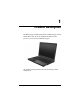
Maintenance and Service Guide HP Compaq nw9440 Notebook PC HP Compaq nx9420 Notebook PC Document Part Number: 412725-003 May 2007 This guide is a troubleshooting reference used for maintaining and servicing the computer. It provides comprehensive information on identifying computer features, components, and spare parts; troubleshooting computer problems; and performing computer disassembly procedures.
© Copyright 2006, 2007 Hewlett-Packard Development Company, L.P. Microsoft and Windows are U.S. registered trademarks of Microsoft Corporation. Intel is a trademark or registered trademark of Intel Corporation or its subsidiaries in the United States and other countries. Bluetooth is a trademark owned by its proprietor and used by Hewlett-Packard Company under license. SD Logo is a trademark of its proprietor. The information contained herein is subject to change without notice.
Contents 1 Product Description 1.1 1.2 1.3 1.4 1.5 Features . . . . . . . . . . . . . . . . . . . . . . . . . . . . . . . . . . . 1–2 Resetting the Computer. . . . . . . . . . . . . . . . . . . . . . . 1–4 Power Management. . . . . . . . . . . . . . . . . . . . . . . . . . 1–5 External Components . . . . . . . . . . . . . . . . . . . . . . . . 1–6 Design Overview. . . . . . . . . . . . . . . . . . . . . . . . . . . 1–22 2 Troubleshooting 2.1 Computer Setup. . . . . . . . . . . . . . . . . . . . . . . . .
Contents 4 Removal and Replacement Preliminaries 4.1 Tools Required . . . . . . . . . . . . . . . . . . . . . . . . . . . . . 4.2 Service Considerations . . . . . . . . . . . . . . . . . . . . . . . Plastic Parts . . . . . . . . . . . . . . . . . . . . . . . . . . . . . . . . Cables and Connectors . . . . . . . . . . . . . . . . . . . . . . . 4.3 Preventing Damage to Removable Drives . . . . . . . . 4.4 Preventing Electrostatic Damage . . . . . . . . . . . . . . . 4.
Contents 5.23 5.24 5.25 5.26 5.27 Top Cover . . . . . . . . . . . . . . . . . . . . . . . . . . . . . . . Speaker . . . . . . . . . . . . . . . . . . . . . . . . . . . . . . . . . System Board . . . . . . . . . . . . . . . . . . . . . . . . . . . . USB/Audio Board . . . . . . . . . . . . . . . . . . . . . . . . . PC Card/Smart Card Assembly. . . . . . . . . . . . . . .
Contents iv Maintenance and Service Guide
1 Product Description The HP Compaq nw9440 Notebook PC and HP Compaq nx9420 Notebook PC offer advanced modularity, Intel® Core Duo processors, and extensive multimedia support.
Product Description 1.1 Features ■ The following processors, varying by computer model: ❏ Intel Core Duo T2600 (2.17-GHz) ❏ Intel Core Duo T2500 (2.00-GHz) ❏ Intel Core Duo T2400 (1.83-GHz) ❏ Intel Core Duo T2300 (1.66-GHz) ■ The following displays are available, varying by computer model: ❏ 17.0-inch, WUXGA+WVA, TFT (1920 × 1200) with over 16.8 million colors with AntiGlare ❏ 17.0-inch, WSXGA+WVA, TFT (1680 × 1050) with over 16.8 million colors with AntiGlare ❏ 17.
Product Description ■ ■ ■ ■ ■ ■ ■ ■ Integrated wireless support for Mini Card IEEE 802.11a/b/g or 802.
Product Description 1.2 Resetting the Computer If the computer you are servicing has an unknown password, follow these steps to clear the password. These steps also clear CMOS: 1. Prepare the computer for disassembly (refer to Section 5.3, “Preparing the Computer for Disassembly,” for more information). 2. Remove the real-time clock (RTC) battery (refer to Section 5.9, “RTC Battery,” for more information on removing and replacing the RTC battery). 3. Wait approximately 5 minutes. 4.
Product Description 1.3 Power Management The computer comes with power management features that extend battery operating time and conserve power.
Product Description 1.4 External Components The external components on the front of the computer are shown below and described in Table 1-1. Front Components Table 1-1 Front Components Item Component Function 1 Wireless light On: An integrated wireless device, such as a wireless local area network (LAN) device and/or a Bluetooth® device, is turned on. 2 Power light ■ On: The computer is on. ■ Blinking: The computer is in standby.
Product Description Table 1-1 Front Components (Continued) Item Component Function 3 Battery light ■ Amber: A battery pack is charging. ■ Green: A battery pack is close to full charge capacity. ■ Blinking amber: A battery pack that is the only available power source has reached a low-battery condition. When the battery reaches a critical low-battery condition, the battery light begins blinking more quickly.
Product Description The external components on the right side of the computer are shown below and described in Table 1-2.
Product Description Table 1-2 Right-Side Components Item Component Function 1 Audio-out (headphone) jack Connect optional headphones or powered stereo speakers. Also connects the audio function of an audio/video device such as a television or VCR. 2 Audio-in (microphone) jack Connects an optional monaural microphone. 3 USB ports (2) Connect USB 1.1- and 2.0-compliant devices to the computer using a standard USB cable, or connect an optional External MultiBay II to the computer.
Product Description The external components on the left side of the computer are shown below and described in Table 1-3. Left-Side Components Table 1-3 Left-Side Components Item Component Function 1 Exhaust vent Provides airflow to cool internal components. Ä To prevent overheating, do not obstruct vents. Do not allow a hard surface, such as a printer, or a soft surface, such as pillows, thick rugs, or clothing, to block airflow.
Product Description Table 1-3 Left-Side Components (Continued) Item Component Function 6 1394 port Connects an optional 1394a device such as a scanner, digital camera, or digital camcorder. 7 Smart card slot Supports optional smart cards. 8 PC Card slot Supports optional Type I, Type II, or Type III 32-bit (CardBus) or 16-bit PC Cards.
Product Description The external components on the rear panel of the computer are shown below and described in Table 1-4.
Product Description Table 1-4 Rear Panel Components Item Component Function 1 Security cable slot Attaches an optional security cable to the computer. Ä Security solutions are designed to act as deterrents. These deterrents may not prevent a product from being mishandled or stolen. 2 Battery bay Holds a battery pack. 3 Exhaust vent Provides airflow to cool internal components. Ä 4 RJ-11 (modem) jack Maintenance and Service Guide To prevent overheating, do not obstruct vents.
Product Description The standard keyboard components of the computer are shown below and described in Table 1-5.
Product Description Table 1-5 Standard Keyboard Components Item Component Function 1 f1 to f12 keys (12) Perform system and application tasks. When combined with the fn key, several keys and buttons perform additional tasks as hotkeys. 2 caps lock key Enables caps lock and turns on the caps lock light. 3 fn key Executes frequently used system functions when pressed in combination with a function key or the esc key. 4 Windows logo key In Windows, displays the Windows Start menu.
Product Description The computer top components are shown below and described in Table 1-6. Top Components Table 1-6 Top Components Item Component Function 1 Power light ■ On: The computer is on. ■ Blinking: The computer is in standby. ■ Blinking rapidly: An AC adapter with a higher power rating should be connected. ■ Off: The computer is off or in hibernation. Power button When the computer is: ■ Off, press to turn on the computer. ■ On, briefly press to initiate hibernation.
Product Description Table 1-6 Top Components (Continued) Item Component Function 2 Wireless button Turns the wireless functionality on or off, but does not create a wireless connection. establish a wireless connection, ✎ To a wireless network must already be set up. 3 Wireless light On: An integrated wireless device, such as a wireless local area network (LAN) device and/or a Bluetooth® device, is turned on. Info Center button Enables you to view a list of commonly used software solutions.
Product Description The computer pointing device components shown below and described in Table 1-7.
Product Description Table 1-7 Pointing Device Components Item Component Function 1 Pointing stick (select models only) Moves the pointer and selects or activates items on the screen. 2 Pointing stick buttons (select models only) Function like the left, middle, and right buttons on an external mouse. 3 TouchPad Moves the pointer and selects or activates items on the screen. Can be set to perform other mouse functions, such as scrolling, selecting, and double-clicking.
Product Description The external components on the bottom of the computer are shown below and described in Table 1-8. Bottom Components Table 1-8 Bottom Components Item Component Function 1 Primary battery bay Holds the primary battery pack. 2 Primary battery locking latch Secures the primary battery pack into the battery bay. 3 Docking connector Connects the computer to an optional docking device.
Product Description Table 1-8 Bottom Components (Continued) Item Component Function 5 Memory module compartment Contains one memory slot that supports replaceable memory modules. Mini Card compartment Holds an optional wireless LAN device. Ä To prevent an unresponsive system and the display of a warning message, install only a Mini Card device authorized for use in your computer by the governmental agency that regulates wireless devices in your country.
Product Description 1.5 Design Overview This section presents a design overview of key parts and features of the computer. Refer to Chapter 3, “Illustrated Parts Catalog,” to identify replacement parts, and Chapter 5, “Removal and Replacement Procedures,” for disassembly steps.
2 Troubleshooting Å WARNING: Only authorized technicians trained by HP should repair this equipment. All troubleshooting and repair procedures are detailed to allow only subassembly-/module-level repair. Because of the complexity of the individual boards and subassemblies, do not attempt to make repairs at the component level or modifications to any printed wiring board. Improper repairs can create a safety hazard.
Troubleshooting 1. Open Computer Setup by turning on or restarting the computer, and then pressing f10 while the “F10 = ROM Based Setup” message is displayed in the lower-left corner of the screen. In Computer Setup, the following shortcuts are available: ❏ To change the language, press f2. ❏ To view navigation information, press f1. ❏ To close open dialog boxes and return to the main Computer Setup screen esc. 2. Select the Files, Security, Diagnostics, or System Configuration menu. 3.
Troubleshooting Computer Setup Defaults To return all settings in Computer Setup to the values that were set at the factory: 1. Open Computer Setup by turning on or restarting the computer, and then pressing f10 while the “F10 = ROM Based Setup” message is displayed in the lower-left corner of the screen. In Computer Setup, the following shortcuts are available: ❏ To change the language, press f2. ❏ To view navigation information, press f1.
Troubleshooting Computer Setup Menus The menu tables in this section provide an overview of Computer Setup options. of the Computer Setup menu items listed in this chapter ✎ Some may not be supported by your computer. Table 2-1 File Menu Select To Do This System Information ■ View identification information for the computer and the battery packs in the system. ■ View specification information for the processor, cache and memory size, system ROM, video revision, and keyboard controller version.
Troubleshooting Table 2-2 Security Menu Select To Do This Setup password Enter, change, or delete a setup password. Power-on password Enter, change, or delete a power-on password. Password options ■ Enable/disable stringent security. ■ Enable/disable password requirement on computer restart. DriveLock passwords ■ Enable/disable DriveLock on any computer hard drive and optional MultiBay hard drives. ■ Change a DriveLock user or master password.
Troubleshooting Table 2-2 Security Menu (Continued) Select To Do This System IDs Enter user-defined computer asset and ownership tag. Disk Sanitizer Run Disk Sanitizer to destroy all existing data on the primary hard drive. The following options are available: Runs the Disk Sanitizer erase cycle ✎ Fast: once. Runs the Disk Sanitizer erase ✎ Optimum: cycle 3 times. Allows you to select the desired ✎ Custom: number of Disk Sanitizer erase cycles from a list.
Troubleshooting Table 2-4 System Configuration Menu Select To Do This Language (or press f2). Change the Computer Setup language. Boot options ■ ■ ■ ■ Set f9, f10, and f12 delay when starting up. Enable/disable CD-ROM boot. Enable/disable Floppy boot. Enable/disable internal network adapter boot and set the boot mode (PXE or RPL). ■ Enable/disable MultiBoot, which sets a boot order that can include most boot devices in the system. ■ Set the boot order.
Troubleshooting Table 2-4 System Configuration Menu (Continued) Select To Do This Device configurations ■ Swap the functions of the fn key and left ctrl key. ■ Enable/disable multiple standard pointing devices at startup. (To set the computer to support only a single, usually nonstandard, pointing device at startup, select Disable.) ■ Enable/disable USB legacy support.
Troubleshooting Table 2-4 System Configuration Menu (Continued) Select To Do This Device configurations (Continued) ■ Enable/disable SATA Native Support. ■ Enable/disable Dual Core CPU. ■ Enable/disable Secondary Battery Fast Charge. Built-In Device Options ■ Enable/disable embedded WWAN Device Radio. ■ Enable/disable embedded WLAN Device Radio. ■ Enable/disable embedded Bluetooth® Device ■ Radio. ■ Enable/disable LAN/WLAN Switching.
Troubleshooting 2.2 Troubleshooting Flowcharts Table 2-5 Troubleshooting Flowcharts Overview Flowchart Description 2.1 “Flowchart 2.1—Initial Troubleshooting” 2.2 “Flowchart 2.2—No Power, Part 1” 2.3 “Flowchart 2.3—No Power, Part 2” 2.4 “Flowchart 2.4—No Power, Part 3” 2.5 “Flowchart 2.5—No Power, Part 4” 2.6 “Flowchart 2.6—No Video, Part 1” 2.7 “Flowchart 2.7—No Video, Part 2” 2.8 “Flowchart 2.8—Nonfunctioning Docking Device (if applicable)” 2.9 “Flowchart 2.
Troubleshooting Flowchart 2.1—Initial Troubleshooting Begin troubleshooting. N Go to Is there power? “Flowchart 2.2—No Power, Part 1.” Y N Check LED board, speaker connections. Beeps, LEDs, or error messages? N Y Go to All drives working? N Go to Is there video? (no boot) Y “Flowchart 2.6—No Video, Part 1.” N Keyboard/ pointing device working? Y N Go to Is the OS loading? N Go to Is there sound? Y “Flowchart 2.9—No Operating System (OS) Loading.” Y “Flowchart 2.15—No Audio, Part 1.
Troubleshooting Flowchart 2.2—No Power, Part 1 No power (power LED is off). Remove from docking device (if applicable). N N Power up on battery power? Go to Power up on battery power? Reset power.* “Flowchart 2.3—No Power, Part 2.” Y Y N N Power up on AC power? Power up on AC power? Reset power.* Y Go to “Flowchart 2.4—No Power, Part 3.” Y Y Power up in docking device? Done *NOTES N 1. Reset the power cables in the docking device and at the AC outlet. 2.
Troubleshooting Flowchart 2.3—No Power, Part 2 Continued from “Flowchart 2.2—No Power, Part 1.” Visually check for debris in battery socket and clean if necessary. Y Power on? Done N Check battery pack by recharging it, moving it to another computer, N Replace power supply (if applicable). Power on? Y N Go to Done Power on? “Flowchart 2.4—No Power, Part 3.
Troubleshooting Flowchart 2.4—No Power, Part 3 Continued from “Flowchart 2.3—No Power, Part 2.” Plug directly into AC outlet. Y Power LED on? Done N Reseat AC adapter in computer and at power source. Y Done Power on? N External N Try different outlet. Power outlet active? Y Internal or external AC adapter? Replace external AC adapter. N Internal Go to “Flowchart 2.5—No Power, Part 4.” Replace power cord.
Troubleshooting Flowchart 2.5—No Power, Part 4 Continued from “Flowchart 2.4—No Power, Part 3.” Open computer. Y Loose or damaged parts? N Reseat loose components and boards and replace damaged items. Close computer and retest. N Power on? Replace the following items (if applicable). Check computer operation after each replacement: 1. Internal DC-DC converter* 2. Internal AC adapter 3. Processor board* 4. System board* *NOTE: Replace these items as a set to prevent shorting out among components.
Troubleshooting Flowchart 2.6—No Video, Part 1 No video. Docking Device Go to Stand-alone or docking device? *NOTE: To change from internal to external display, use the hotkey combination. “Flowchart 2.7—No Video, Part 2.” Stand-alone Internal or external display*? Y Adjust brightness. A Adjust brightness. Press lid switch to ensure operation. Y Video OK? Done N Internal External Video OK? Y Done N Video OK? Done N Replace the following one at a time. Test after each replacement. 1.
Troubleshooting Flowchart 2.7—No Video, Part 2 Continued from “Flowchart 2.6—No Video, Part 1.” Remove computer from docking device, if connected. Adjust display brightness. Check brightness of external monitor. N Y Go to “A” in “Flowchart 2.6—No Video, Part 1.” Video OK? Y Video OK? Done N Check that computer is properly seated in docking device, for bent pins on cable, and for monitor connection. Try another external monitor.
Troubleshooting Flowchart 2.8—Nonfunctioning Docking Device (if applicable) Nonfunctioning docking device. Reset power cord in docking device and power outlet. Check voltage setting on docking device. Reset monitor cable connector at docking device. Reinstall computer into docking device. Y Docking device operating? N Y Docking device operating? Done Done N Replace docking device. 2–18 Test replacement docking device with new computer.
Troubleshooting Flowchart 2.9—No Operating System (OS) Loading No OS loading.* Reset power cord in docking device and power outlet. No OS loading from hard drive, go to “Flowchart 2.10—No OS Loading, Hard Drive, Part 1.” No OS loading from diskette drive, go to “Flowchart 2.13—No OS Loading, Diskette Drive.” No OS loading from CD-ROM or DVD-ROM drive, go to “Flowchart 2.14—No OS Loading, Optical Drive.” No OS loading from network, go to “Flowchart 2.20—No Network/Modem Connection.
Troubleshooting Flowchart 2.10—No OS Loading, Hard Drive, Part 1 OS not loading from hard drive. Y Nonsystem disk message? N Go to “Flowchart 2.11—No OS Loading, Hard Drive, Part 2.” Reseat external hard drive. Y OS loading? Done N N Boot from CD? N Y Boot from diskette? Check the Setup utility for correct booting order. Y Change boot priority through the Setup Utility and reboot. N Boot from hard drive? N Y Boot from hard drive? Done Y 2–20 Go to “Flowchart 2.
Troubleshooting Flowchart 2.11—No OS Loading, Hard Drive, Part 2 Continued from “Flowchart 2.10—No OS Loading, Hard Drive, Part 1.” Reseat hard drive. N 1. Replace hard drive. 2. Replace system board. CD or diskette in drive? Y Hard drive accessible? Y Done N Remove diskette and reboot. Run FDISK. Y Boot from hard drive? N Done N Hard drive partitioned? Y N Y N Go to “Flowchart 2.13—No OS Loading, Diskette Drive.
Troubleshooting Flowchart 2.12—No OS Loading, Hard Drive, Part 3 Continued from “Flowchart 2.11—No OS Loading, Hard Drive, Part 2.” N System files on hard drive? Install OS and reboot. Y Y Y Virus on hard drive? OS loading from hard drive? Clean virus. N Done N Y Run SCANDISK and check for bad sectors. Diagnostics on diskette? Replace hard drive. N N Can bad sectors be fixed? Run diagnostics and follow recommendations. Replace hard drive. Y N Boot from hard drive? Fix bad sectors.
Troubleshooting Flowchart 2.13—No OS Loading, Diskette Drive Y OS not loading from diskette drive. Reseat diskette drive. OS loading? Done N Y N Bootable diskette in drive? Nonsystem disk message? N Y N Check diskette for system files. Try different diskette. Go to Boot from another device? “Flowchart 2.17—Nonfunctioning Device.” Y Y N Diskette drive enabled in the Setup Utility? 1. Replace diskette drive. 2. Replace system board. Nonsystem disk error? Enable drive and cold boot computer.
Troubleshooting Flowchart 2.14—No OS Loading, Optical Drive Y No OS loading from CD-ROM or DVD-ROM drive. N Install bootable disc and reboot computer. Bootable disc in drive? Disc in drive? Y N Install bootable disc. Try another bootable disc. Y Boots from CD or DVD? Done N Y Boots from CD or DVD? Reseat drive. Done N N Booting from another device? Y Y Booting order correct? N Go to “Flowchart 2.17—Nonfunctioning Device.” Reset the computer. Refer to Go to Section 1.
Troubleshooting Flowchart 2.15—No Audio, Part 1 Y Turn up audio internally or externally. No audio. Audio? Done N Y Computer in docking device (if applicable)? N Go to Internal audio? Undock N “Flowchart 2.16—No Audio, Part 2.” Y Go to Replace the docking device. “Flowchart 2.16—No Audio, Part 2.” Y Go to “Flowchart 2.17—Nonfunctioning Device.
Troubleshooting Flowchart 2.16—No Audio, Part 2 Continued from “Flowchart 2.15—No Audio, Part 1.” N Audio driver in OS configured? Reload audio drivers. Y N Correct drivers for application? Load drivers and set configuration in OS. Y Connect to external speaker. N Audio? Y Replace audio board and speaker connections in computer (if applicable). Y Audio? Done N 1. Replace internal speakers. 2. Replace audio board (if applicable). 3. Replace system board.
Troubleshooting Flowchart 2.17—Nonfunctioning Device Nonfunctioning device. Reseat device. Unplug the nonfunctioning device from the computer and inspect cables and plugs for bent or broken pins or other damage. Y Clear CMOS. Fix or replace broken item. Any physical device detected? N Reattach device. Close computer, plug in power, and reboot. Go to “Flowchart 2.9—No Operating System (OS) Loading.” Replace hard drive. N Device boots properly? N Replace NIC.
Troubleshooting Flowchart 2.18—Nonfunctioning Keyboard Keyboard not operating properly. Connect computer to good external keyboard. N External device works? Replace system board. Y Reseat internal keyboard connector (if applicable). N Replace internal keyboard or cable. OK? Y Y Done OK? Done N Replace system board.
Troubleshooting Flowchart 2.19—Nonfunctioning Pointing Device Pointing device not operating properly. Connect computer to good external pointing device. N Replace system board. External device works? Y Reseat internal pointing device connector (if applicable). N Replace internal pointing device or cable. OK? Y Y Done OK? Done N Replace system board.
Troubleshooting Flowchart 2.20—No Network/Modem Connection No network or modem connection. N Network or modem jack active? Replace jack or have jack activated. Y Y Connect to nondigital line. Digital line? N Y N NIC/modem configured in OS? Reload drivers and reconfigure. Done OK? N Y Disconnect all power from the computer and open. Replace the NIC/modem (if applicable). Y Reseat NIC/modem (if applicable). OK? Done N Replace system board.
3 Illustrated Parts Catalog This chapter provides an illustrated parts breakdown and a reference for spare part numbers. 3.1 Serial Number Location When ordering parts or requesting information, provide the computer serial number and model number located on the bottom of the computer.
Illustrated Parts Catalog 3.
Illustrated Parts Catalog Table 3-1 Spare Parts: Computer Major Components Spare Part Number Item Description 1 Display assemblies (include wireless antenna transceivers and cables) 17.0-inch, WUXGA+WVA with AntiGlare 17.0-inch, WSXGA+WVA with AntiGlare 17.0-inch, WXGA+WVA with AntiGlare 17.
Illustrated Parts Catalog Computer Major Components 3–4 Maintenance and Service Guide
Illustrated Parts Catalog Table 3-1 Spare Parts: Computer Major Components (Continued) Spare Part Number Item Description 4 Keyboards without pointing stick For use in: Brazil The Czech Republic Denmark France French Canada Germany Greece Hungary Iceland Internationally Israel Italy Japan Korea Latin America Norway 5 409911-201 409911-221 409911-081 409911-051 409911-121 409911-041 409911-151 409911-211 409911-DD1 409911-021 409911-BB1 409911-061 409911-291 409911-AD1 409911-161 409911-091 The Peopl
Illustrated Parts Catalog Computer Major Components 3–6 Maintenance and Service Guide
Illustrated Parts Catalog Table 3-1 Spare Parts: Computer Major Components (Continued) Item Description 8 TouchPads (include TouchPad cable) 9a 9b 9c Spare Part Number With 3 pointing stick buttons, 2 TouchPad buttons, and fingerprint sensor, for use with keyboards with pointing stick 409952-001 With 3 pointing stick buttons and 3 TouchPad buttons, for use with keyboards with pointing stick 409956-001 With 2 TouchPad buttons and fingerprint sensor, for use with keyboards without pointing stick 4
Illustrated Parts Catalog Computer Major Components 3–8 Maintenance and Service Guide
Illustrated Parts Catalog Table 3-1 Spare Parts: Computer Major Components (Continued) Item 14 Spare Part Number Description Bluetooth® module (includes Bluetooth module cable) 409993-001 15 Speaker 409947-001 16 PC Card/smart card assembly 409943-001 17 System board 409959-001 18 Video board M56, for use with model nx9420 G71, for use with model nw9440 409979-001 417206-001 19 RTC battery 409953-001 20 Base enclosure 409942-001 21 Memory modules, 1-DIMM PC2-5300 2048 MB 1024 MB 512
Illustrated Parts Catalog Computer Major Components 3–10 Maintenance and Service Guide
Illustrated Parts Catalog Table 3-1 Spare Parts: Computer Major Components (Continued) Item Description 23 Mini Card modules Spare Part Number 802.11b/g HS WLAN module for use in North America 407107-001 802.11b/g HS WLAN module for use in the countries listed below. These countries are categorized as the rest of the world (ROW). 407107-002 China Ecuador Haiti Honduras Pakistan Peru Qatar South Korea Uruguay Venezuela 802.11b/g HS WLAN module for use in Japan 407107-291 802.
Illustrated Parts Catalog Computer Major Components 3–12 Maintenance and Service Guide
Illustrated Parts Catalog Table 3-1 Spare Parts: Computer Major Components (Continued) Spare Part Number Item Description 23 Mini Card modules (Continued) 802.11a/b/g GL WLAN module for use in the countries listed below. These countries are categorized as most of the world (MOW 2).
Illustrated Parts Catalog Computer Major Components 3–14 Maintenance and Service Guide
Illustrated Parts Catalog Table 3-1 Spare Parts: Computer Major Components (Continued) Spare Part Number Item Description 23 Mini Card modules (Continued) 24 802.11b/g GL WLAN module for use in the following countries: 409250-004 Israel Jordan Ukraine United Arab Emirates 409983-001 409991-001 5400 rpm 100 GB 80 GB 60 GB Hard drives 7200 rpm 100 GB 80 GB 25 Kuwait Thailand Battery pack (8-cell, 4.
Illustrated Parts Catalog 3.
Illustrated Parts Catalog Table 3-2 Display Assembly Components Spare Part Number Information Item Description Spare Part Number 1 Display bezel 409935-001 2 Display Hinge Kit 409937-001 3 Display panels 17.0-inch, WUXGA+WVA with AntiGlare 17.0-inch, WSXGA+WVA with AntiGlare 17.0-inch, WXGA+WVA with AntiGlare 17.
Illustrated Parts Catalog 3.
Illustrated Parts Catalog 3.
Illustrated Parts Catalog 3.
Illustrated Parts Catalog 3.
Illustrated Parts Catalog Table 3-6 Miscellaneous (Not Illustrated) Spare Part Information (Continued) Description Spare Part Number Power cords: For use in the United States 350055-001 For use in Australia 350055-011 For use in Europe 350055-021 For use in the United Kingdom 350055-031 For use in Italy 350055-061 For use in Denmark 350055-081 For use in Brazil 350055-201 For use in Japan 350055-291 For use in the People’s Republic of China 350055-AA1 For use in Korea 350055-AD1 For u
Illustrated Parts Catalog Table 3-6 Miscellaneous (Not Illustrated) Spare Part Information (Continued) Description Spare Part Number USB 1.1 diskette drive 359118-001 Screw Kit (includes the following screws; refer to Appendix A, “Screw Listing,” for more information on specifications and usage) 409945-001 ■ ■ ■ ■ Hex socket HM5.0×9.0 screw lock Phillips PM3.0×3.0 screw Phillips PM2.5×17.0 screw Phillips PM2.5×13.0 spring-loaded screw ■ Phillips PM2.5×7.0 screw ■ Phillips PM2.5×4.
Illustrated Parts Catalog 3.8 Sequential Part Number Listing Table 3-7 Sequential Part Number Listing Spare Part Number Description 325814-001 Nylon carrying case 359118-001 USB 1.
Illustrated Parts Catalog Table 3-7 Sequential Part Number Listing (Continued) Spare Part Number Description 380089-001 HP Docking Station Miscellaneous Plastics Kit 391173-001 90-watt PFC AC adapter 391174-001 120-watt PFC AC adapter 398682-001 8-cell, 4.8-AH battery pack 407107-001 802.11b/g HS WLAN Mini Card module for use in North America 407107-002 802.
Illustrated Parts Catalog Table 3-7 Sequential Part Number Listing (Continued) Spare Part Number 407576-002 Description 802.
Illustrated Parts Catalog Table 3-7 Sequential Part Number Listing (Continued) Spare Part Number Description 409911-021 Keyboard without pointing stick for use internationally (includes Pointing Stick cable) 409911-031 Keyboard without pointing stick for use in the United Kingdom (includes pointing stick cable) 409911-041 Keyboard without pointing stick for use in Germany (includes pointing stick cable) 409911-051 Keyboard without pointing stick for use in France (includes pointing stick cable) 4
Illustrated Parts Catalog Table 3-7 Sequential Part Number Listing (Continued) Spare Part Number Description 409911-171 Keyboard without pointing stick for use in Saudi Arabia (includes pointing stick cable) 409911-201 Keyboard without pointing stick for use in Brazil (includes pointing stick cable) 409911-211 Keyboard without pointing stick for use in Hungary (includes pointing stick cable) 409911-221 Keyboard without pointing stick for use in the Czech Republic (includes pointing stick cable) 4
Illustrated Parts Catalog Table 3-7 Sequential Part Number Listing (Continued) Spare Part Number Description 409913-001 Keyboard with pointing stick for use in the United States (includes pointing stick cable) 409913-021 Keyboard with pointing stick for use internationally (includes pointing stick cable) 409913-031 Keyboard with pointing stick for use in the United Kingdom (includes pointing stick cable) 409913-041 Keyboard with pointing stick for use in Germany (includes pointing stick cable) 40
Illustrated Parts Catalog Table 3-7 Sequential Part Number Listing (Continued) Spare Part Number Description 409913-161 Keyboard with pointing stick for use in Latin America (includes pointing stick cable) 409913-171 Keyboard with pointing stick for use in Saudi Arabia (includes pointing stick cable) 409913-201 Keyboard with pointing stick for use in Brazil (includes pointing stick cable) 409913-211 Keyboard with pointing stick for use in Hungary (includes pointing stick cable) 409913-221 Keyboa
Illustrated Parts Catalog Table 3-7 Sequential Part Number Listing (Continued) Spare Part Number Description 409913-DD1 Keyboard with pointing stick for use in Iceland (includes pointing stick cable) 409931-001 Wireless Antenna Kit 409932-001 Fingerprint sensor board 409933-001 Display Inverter 409934-001 Label Kit 409935-001 Display bezel 409936-001 Display Bracket Kit (includes top, middle, and bottom brackets) 409937-001 Display Hinge Kit 409938-001 Display Cable Kit 409939-001 Disp
Illustrated Parts Catalog Table 3-7 Sequential Part Number Listing (Continued) Spare Part Number Description 409951-001 Top cover with 3 pointing stick buttons and 3 TouchPad buttons, for use with keyboards with Pointing Stick 409952-001 Top cover with 3 pointing stick buttons, 2 TouchPad buttons, and fingerprint sensor, for use with keyboards with Pointing Stick 409953-001 RTC battery 409954-001 Top cover with 2 TouchPad buttons and fingerprint sensor, for use with keyboards without pointing stic
Illustrated Parts Catalog Table 3-7 Sequential Part Number Listing (Continued) Spare Part Number Description 409968-001 USB/audio board (includes audio board cable and USB board cable) 409969-001 Intel Core Duo T2300 (1.67-GHz) processor (includes thermal paste) 409970-001 Intel Core Duo T2400 (1.83-GHz) processor (includes thermal paste) 409971-001 Intel Core Duo T2500 (2.00-GHz) processor (includes thermal paste) 409972-001 Intel Core Duo T2600 (2.
Illustrated Parts Catalog Table 3-7 Sequential Part Number Listing (Continued) Spare Part Number Description 409985-001 2X Max DVD/CD-RW Combo Drive (includes bezel and optical drive bracket) 409986-001 DVD±RW and CD-RW Double-Layer Combo Drive (includes bezel and optical drive bracket) 409987-001 DVD±RW and CD-RW Double-Layer Combo Drive with LightScribe (includes bezel and optical drive bracket) 409989-001 17.
4 Removal and Replacement Preliminaries This chapter provides essential information for proper and safe removal and replacement service. 4.1 Tools Required You will need the following tools to complete the removal and replacement procedures: ■ Magnetic screwdriver ■ Phillips P0 and P1 screwdrivers ■ Torx8 screwdriver ■ 5.
Removal and Replacement Preliminaries 4.2 Service Considerations The following sections include some of the considerations that you should keep in mind during disassembly and assembly procedures. you remove each subassembly from the computer, place ✎ As the subassembly (and all accompanying screws) away from the work area to prevent damage. Plastic Parts Using excessive force during disassembly and reassembly can damage plastic parts. Use care when handling the plastic parts.
Removal and Replacement Preliminaries 4.3 Preventing Damage to Removable Drives Removable drives are fragile components that must be handled with care. To prevent damage to the computer, damage to a removable drive, or loss of information, observe the following precautions: ■ Before removing or inserting a hard drive, shut down the computer. If you are unsure whether the computer is off or in hibernation, turn the computer on, and then shut it down through the operating system.
Removal and Replacement Preliminaries 4.4 Preventing Electrostatic Damage Many electronic components are sensitive to electrostatic discharge (ESD). Circuitry design and structure determine the degree of sensitivity. Networks built into many integrated circuits provide some protection, but in many cases, the discharge contains enough power to alter device parameters or melt silicon junctions.
Removal and Replacement Preliminaries 4.5 Packaging and Transporting Precautions Use the following grounding precautions when packaging and transporting equipment: ■ To avoid hand contact, transport products in static-safe containers, such as tubes, bags, or boxes. ■ Protect all electrostatic-sensitive parts and assemblies with conductive or approved containers or packaging. ■ Keep electrostatic-sensitive parts in their containers until the parts arrive at static-free workstations.
Removal and Replacement Preliminaries 4.6 Workstation Precautions Use the following grounding precautions at workstations: ■ Cover the workstation with approved static-shielding material (refer to Table 4-2, “Static-Shielding Materials”). ■ Use a wrist strap connected to a properly grounded work surface and use properly grounded tools and equipment. ■ Use conductive field service tools, such as cutters, screwdrivers, and vacuums.
Removal and Replacement Preliminaries 4.7 Grounding Equipment and Methods Grounding equipment must include either a wrist strap or a foot strap at a grounded workstation. ■ When seated, wear a wrist strap connected to a grounded system. Wrist straps are flexible straps with a minimum of one megohm ±10% resistance in the ground cords. To provide proper ground, wear a strap snugly against the skin at all times. On grounded mats with banana-plug connectors, use alligator clips to connect a wrist strap.
Removal and Replacement Preliminaries Table 4-1 shows how humidity affects the electrostatic voltage levels generated by different activities.
5 Removal and Replacement Procedures This chapter provides removal and replacement procedures. There are as many as 101 screws and screw locks, in 12 different sizes, that must be removed, replaced, or loosened when servicing the computer. Make special note of each screw and screw lock size and location during removal and replacement. Refer to Appendix A, “Screw Listing” for detailed information on screw and screw lock sizes, locations, and usage. 5.
Removal and Replacement Procedures 5.2 Disassembly Sequence Chart Use the chart below to determine the section number to be referenced when removing computer components. Disassembly Sequence Chart Section Description 5.3 Preparing the Computer for Disassembly # of Screws Removed Battery pack 0 5.4 Hard Drive 2 loosened to remove the hard drive cover 1 loosened to remove the hard drive 4 to disassemble the hard drive 5.5 Computer Feet 0 5.6 Bluetooth Module 0 5.
Removal and Replacement Procedures Disassembly Sequence Chart (Continued) Section Description # of Screws Removed 5.10 Optical Drive 1 to remove the optical drive 2 to remove the optical drive bracket 5.11 Keyboard 4 5.12 Internal Memory Module 0 5.13 TouchPad 1 5.14 Modem Module 2 5.15 Switch Cover 4 5.16 LED Board 5 5.17 Fan Assembly 2 5.18 Processor Heat Sink 4 loosened 5.19 Processor 1 loosened 5.20 Video Board Heat Sink 4 loosened 2 removed 5.
Removal and Replacement Procedures 5.3 Preparing the Computer for Disassembly Before you begin any removal or installation procedures: 1. Shut down the computer. If you are unsure whether the computer is off or in hibernation, turn the computer on, and then shut it down through the operating system. 2. Disconnect all external devices connected to the computer. 3. Disconnect the power cord. Battery Pack Spare Part Number Information 8-cell, 4.8-Ah battery pack 398682-001 4.
Removal and Replacement Procedures b. Slide and hold the battery pack locking latch 1 to the right. (The battery pack disengages from the computer.) c. Slide the battery pack release latch 2 to the right. d. Slide the battery pack 3 straight back and remove it. Removing the Battery Pack Reverse the above procedure to install the battery pack.
Removal and Replacement Procedures 5.4 Hard Drive Hard Drive Spare Part Number Information 7200 rpm 100 GB 80 GB 409983-001 409991-001 5400 rpm 100 GB 80 GB 60 GB 409982-001 409981-001 409980-001 1. Prepare the computer for disassembly (refer to Section 5.3). 2. Position the computer with the front toward you.
Removal and Replacement Procedures 3. Loosen the two Phillips PM2.5×17.0 screws 1 that secure the hard drive cover to the computer. 4. Lift the right side of the hard drive cover 2 and swing it to the left. 5. Remove the hard drive cover. hard drive cover is included in the Plastics Kit, spare part ✎ The number 409944-001.
Removal and Replacement Procedures 6. Loosen the Phillips PM2.5×13.0 spring-loaded hard drive retention screw 1. 7. Grasp the mylar tab 2 on the hard drive and slide the hard drive to the left 3 to disconnect it from the system board. 8. Remove the hard drive 4 from the hard drive bay.
Removal and Replacement Procedures 9. Remove the four Phillips PM3.0×3.0 hard drive frame screws 1 from each side of the hard drive. 10. Lift the frame 2 straight up to remove it from the hard drive. Removing the Hard Drive Frame Reverse the above procedure to reassemble and install the hard drive.
Removal and Replacement Procedures 5.5 Computer Feet The computer feet are adhesive-backed rubber pads. The feet are included in the Plastics Kit, spare part number 409944-001.
Removal and Replacement Procedures 5.6 Bluetooth Module Bluetooth Module Spare Part Number Information Bluetooth module (includes Bluetooth module cable) 409993-001 1. Prepare the computer for disassembly (refer to Section 5.3). 2. Remove the hard drive (Section 5.4). 3. Slide the Bluetooth module 1 out of the clip in the hard drive compartment. 4. Remove the Bluetooth module 2 from the hard drive. 5. Disconnect the Bluetooth module cable 3 from the module.
Removal and Replacement Procedures 5.7 External Memory Module Memory Module Spare Part Number Information 1-DIMM, PC2-5300 2048 MB 1024 MB 512 MB 256 MB 409967-001 409966-001 409965-001 409964-001 1-DIMM, PC2-4200 2048 MB 1024 MB 512 MB 256 MB 409963-001 409962-001 409961-001 409960-001 1. Prepare the computer for disassembly (refer to Section 5.3). 2. Position the computer with the front toward you. 3. Loosen the three Phillips PM2.5×4.
Removal and Replacement Procedures 6. Spread the retaining tabs 1 on each side of the memory module socket to release the memory module. (The edge of the module opposite the socket rises away from the computer.) 7. Slide the module 2 away from the socket at an angle. 8. Remove the memory module. modules are designed with notches 3 to prevent ✎ Memory incorrect installation into the memory module socket. Removing the Memory Module Reverse the above procedure to install a memory module.
Removal and Replacement Procedures 5.8 Mini Card Module Mini Card Module Spare Part Number Information 802.11b/g HS WLAN module for use in North America 407107-001 802.11b/g HS WLAN module for use in the ROW countries listed below. 407107-002 China Ecuador Haiti Honduras Pakistan Peru Qatar South Korea Uruguay Venezuela 802.11b/g HS WLAN module for use in Japan 407107-291 802.11b/g LJ WLAN module for use in North America 407108-001 802.
Removal and Replacement Procedures Mini Card Module Spare Part Number Information (Continued) 802.11a/b/g GL WLAN module for use in the MOW 2 countries listed below.
Removal and Replacement Procedures 2. Remove the memory/Mini Card module compartment cover (Section 5.7). 3. Before disconnecting the wireless antenna cables, make note of which cable is attached to which antenna clip on the Mini Card module, then disconnect the auxiliary and main wireless antenna cables 1 from the Mini Card module. wireless antenna cables are available in the Wireless ✎ The Antenna Transceiver and Cable Kit, spare part number 409931-001. 4. Remove the two Phillips PM2.0×4.
Removal and Replacement Procedures 5.9 RTC Battery RTC Battery Spare Part Number Information RTC battery 409953-001 1. Prepare the computer for disassembly (Section 5.3). 2. Remove the memory/Mini Card module compartment cover (Section 5.7). 3. Use a non-conductive, flat-bladed tool to pry the RTC battery out of the socket. Removing the RTC Battery Reverse the above procedure to install the RTC battery. Make sure the RTC battery is installed with the “+” sign facing up.
Removal and Replacement Procedures 5.10 Optical Drive Optical Drive Spare Part Number Information optical drive spare part kits include an optical drive bezel and optical ✎ All drive bracket. DVD±RW and CD-RW Double-Layer Combo Drive with LightScribe 409987-001 DVD±RW and CD-RW Double-Layer Combo Drive 409986-001 2X Max DVD/CD-RW Combo Drive 409985-001 8X Max DVD/CD-RW Combo Drive 409984-001 1. Prepare the computer for disassembly (Section 5.3). 2. Position the computer with right side toward you.
Removal and Replacement Procedures 3. Remove the Torx8 T8M2.5×9.0 screw 1 that secures the optical drive to the computer. 4. Use a flat-bladed tool to push the metal tab 2 toward the right side of the computer. (The optical drive partially removes from the optical drive bay.) 5. Slide the optical drive 3 out of the computer. 6. Remove the optical drive. Removing the Optical Drive 7. If it is necessary to replace the optical drive bracket, remove the two Phillips PM2.0×4.
Removal and Replacement Procedures 5.
Removal and Replacement Procedures Keyboard Spare Part Number Information (Continued) Keyboards without pointing stick for use in: Brazil The Czech Republic Denmark France French Canada Germany Greece Hungary Iceland Internationally Israel Italy Japan Korea Latin America 409911-201 409911-221 409911-081 409911-051 409911-121 409911-041 409911-151 409911-211 409911-DD1 409911-021 409911-BB1 409911-061 409911-291 409911-AD1 409911-161 Norway The People’s Republic of China Portugal Russia Saudi Arabia Slova
Removal and Replacement Procedures 3. Remove the four Torx8 T8M2.5×9.0 screws that secure the keyboard to the computer. Removing the Keyboard Screws 4. Turn the computer display-side up with the front toward you. 5. Open the computer as far as possible. 6. Lift the rear edge of the keyboard and swing it toward you until it rests on the palm rest.
Removal and Replacement Procedures 7. Release the zero insertion force (ZIF) connector 1 to which the keyboard cable is attached and disconnect the keyboard cable 2. 8 applies only to computer models equipped with a ✎ Step pointing stick. 8. Release the ZIF connector 3 to which the pointing stick cable is attached and disconnect the pointing stick cable 4. 9. Remove the keyboard. Disconnecting the Keyboard and Pointing Stick Cables Reverse the above procedure to install the keyboard.
Removal and Replacement Procedures 5.12 Internal Memory Module Memory Module Spare Part Number Information 1-DIMM, PC2-5300 2048 MB 1024 MB 512 MB 256 MB 409967-001 409966-001 409965-001 409964-001 1-DIMM, PC2-4200 2048 MB 1024 MB 512 MB 256 MB 409963-001 409962-001 409961-001 409960-001 1. Prepare the computer for disassembly (Section 5.3). 2. Release the keyboard (Section 5.11).
Removal and Replacement Procedures 3. Spread the retaining tabs 1 on each side of the memory module socket to release the memory module. (The edge of the module opposite the socket rises away from the computer.) 4. Slide the module 2 away from the socket at an angle . 5. Remove the memory module. modules are designed with notches 3 to prevent ✎ Memory incorrect installation into the memory module socket. Removing the Memory Module Reverse the above procedure to install a memory module.
Removal and Replacement Procedures 5.13 TouchPad TouchPad Spare Part Number Information ✎ All TouchPad spare part kits include a TouchPad cable.
Removal and Replacement Procedures 4. Remove the Torx8 T8M2.5×9.0 screw that secures the TouchPad to the computer.
Removal and Replacement Procedures 5. Turn the computer display-side up with the front toward you. 6. Open the computer. 7. Disconnect the TouchPad cable 1 from the system board. 8 applies only to computer models equipped with a ✎ Step fingerprint reader. 8. Disconnect the fingerprint reader cable 3 from the system board. 9. Lift up on the rear edge of the TouchPad 3 to disengage it from the top cover. 10. Remove the TouchPad.
Removal and Replacement Procedures 11. If it is necessary to replace the TouchPad cable, turn the TouchPad upside down. 12. Disconnect the TouchPad cable 1 from the TouchPad board. 13. Remove the TouchPad cable from the clips 2 in the TouchPad frame. TouchPad cable is included in the Cable Kit, spare part ✎ The number 409990-001. Removing the TouchPad Cable Reverse the above procedure to install the TouchPad.
Removal and Replacement Procedures 5.14 Modem Module Modem Module Spare Part Number Information Modem module 409941-001 1. Prepare the computer for disassembly (Section 5.3). 2. Remove the keyboard (Section 5.11). 3. Remove the TouchPad (Section 5.13).
Removal and Replacement Procedures 4. Remove the two Phillips PM2.0×4.0 screws 1 that secure the modem module to the system board. 5. Lift the right side of the modem module 2 to disconnect it from the system board. 6. Disconnect the modem cable 3 from the modem module. modem cable is included in the Cable Kit, spare part ✎ The number 409990-001. 7. Remove the modem module. Removing the Modem Module Reverse the above procedure to install the modem module.
Removal and Replacement Procedures 5.15 Switch Cover Switch Cover Spare Part Number Information Switch cover 409948-001 Lid switch board 409958-001 1. Prepare the computer for disassembly (Section 5.3). 2. Turn the computer upside down with the rear panel toward you. 3. Remove the four Torx8 T8M2.5×4.0 screws in the battery bay that secure the switch cover to the computer.
Removal and Replacement Procedures 4. Turn the computer display-side up with front toward you. 5. Open the computer as far as possible. 6. Insert a thin flat-bladed tool under the hinge cover sections 1 of the switch cover and lift up until the switch cover 2 disengages from the computer. 7. Remove the switch cover. Removing the Switch Cover Reverse the above procedure to install the switch cover.
Removal and Replacement Procedures 5.16 LED Board LED Board Spare Part Number Information LED board (includes LED board cable) 409957-001 1. Prepare the computer for disassembly (Section 5.3). 2. Remove the switch cover (Section 5.15). 3. Remove the four Torx8 T8M2.5×4.0 screws 1 and the Torx8 T8M2.5×19.0 screw 2 that secure the LED board to the computer. 4. Lift up on the LED board 3 between the volume decrease and volume increase buttons to disconnect the LED board from the system board. 5.
Removal and Replacement Procedures 5.17 Fan Assembly Fan Assembly Spare Part Number Information Fan Assembly 409932-001 1. 2. 3. 4. Prepare the computer for disassembly (Section 5.3). Release the keyboard (Section 5.11). Disconnect the fan cable 1 from the system board. Remove the two Torx8 T8M2.5×7.0 screws 2 that secure the fan assembly to the base enclosure. 5. Lift the left side of the fan 3 until it clears the left side of the base enclosure. 6.
Removal and Replacement Procedures 5.18 Processor Heat Sink Processor Heat Sink Spare Part Number Information Processor heat sink (includes thermal paste) 409949-001 1. Prepare the computer for disassembly (Section 5.3). 2. Release the keyboard (Section 5.11). 3. Remove the fan assembly (Section 5.17). 4. Loosen the four Phillips PM2.5×7.0 screws 1 that secure the heat sink to the system board. 5. Lift the front edge of the heat sink 2 to disengage it from the processor.
Removal and Replacement Procedures thermal paste should be thoroughly cleaned from the ✎ The surfaces of the heat sink 1 and processor 2 each time the heat sink is removed. Thermal paste is included with all heat sink and processor spare part kits. Thermal Paste Locations Reverse the above procedure to install the heat sink.
Removal and Replacement Procedures 5.19 Processor Processor Spare Part Number Information ✎ All processor spare part kits include thermal paste. Intel Core Duo T2600 (2.17-GHz) processor Intel Core Duo T2500 (2.00-GHz) processor Intel Core Duo T2400 (1.83-GHz) processor Intel Core Duo T2300 (1.67-GHz) processor 409972-001 409971-001 409970-001 409969-001 1. Prepare the computer for disassembly (Section 5.3), and then remove the following components: a. Keyboard (Section 5.11) b. Fan assembly (Section 5.
Removal and Replacement Procedures 2. Use a flat-bladed screwdriver to turn the processor locking screw 1 one-half turn counterclockwise until you hear a click. 3. Lift the processor 2 straight up and remove it. The gold triangle 3 on the processor should be aligned with ✎ the triangle 4 embossed on the processor socket when you install the processor. Removing the Processor Reverse the above procedure to install the processor.
Removal and Replacement Procedures 5.20 Video Board Heat Sink Video Board Heat Sink Spare Part Number Information ✎ All video board heat sink spare part kits include thermal pads. Video board heat sink for use with M56 video board (includes thermal pads) 409950-001 Video board heat sink for use with G71 video board (includes thermal pads) 413489-001 1. Prepare the computer for disassembly (Section 5.3). 2. Release the keyboard (Section 5.11). 3. Remove the fan assembly (Section 5.17).
Removal and Replacement Procedures 4. Loosen the four Phillips PM2.5×7.0 screws 1 that secure the video board heat sink to the computer. 5. Remove the two Torx8 T8M2.5×4.0 screws 2 that secure the top cover hinge to the computer.
Removal and Replacement Procedures 6. Lift the rear edge of the top cover hinge 1 until it rests at an angle. 7. Lift the front edge of the video board heat sink 2 until it clears the top cover hinge, and then slide the video board heat sink forward and remove it. to the adhesive quality of the thermal pad located between ✎ Due the video board heat sink and the video board, it may be necessary to move the heat sink from side to side to detach the video board heat sink.
Removal and Replacement Procedures thermal pads should be thoroughly cleaned from the ✎ The surfaces of the video boards 1 and video board heat sink 2 each time the video board heat sink is removed. Thermal paste is included with all video board heat sink and video board spare part kits. Thermal Paste Locations Reverse the above procedure to install the video board heat sink and fan assembly.
Removal and Replacement Procedures 5.21 Video Board Video Board Spare Part Number Information Video board, M56, for use with model nx9420 Video board, G71, for use with model nw9440 409979-001 417206-001 1. Prepare the computer for disassembly (Section 5.3). 2. Remove the fan assembly (Section 5.17). 3. Remove the video board heat sink (Section 5.20). 4. Use a 5.0-mm hex socket to remove the two HM5.0×9.0 screw locks that secure the video board to the computer.
Removal and Replacement Procedures 5. Lift the front edge of the video board 1 until it clears the top cover hinge. 6. Slide the video board forward 2 at an angle and remove it from the socket. video board is designed with a notch 3 to prevent ✎ The incorrect installation. Removing the Video Board Reverse the above procedure to install the video board.
Removal and Replacement Procedures 5.22 Display Assembly Display Assembly Spare Part Number Information ✎ All display assemblies include wireless antenna transceivers and cables. 17.0-inch, WUXGA+WVA with AntiGlare 17.0-inch, WSXGA+WVA with AntiGlare 17.0-inch, WXGA+WVA with AntiGlare 17.0-inch, WSXGA+WVA with BrightView 409977-001 409975-001 409973-001 409988-001 1. Prepare the computer for disassembly (Section 5.3). 2. Remove the memory/Mini PCI module compartment cover (Section 5.
Removal and Replacement Procedures 4. Close the computer and turn it upside down with the rear panel toward you. 5. Remove the four Torx8 T8M2.5×9.0 screws 1 from the computer bottom that secure the display assembly to the computer. 6. Remove the two Torx8 T8M2.5×9.0 screws 2 from the computer rear panel that secure the display assembly to the computer.
Removal and Replacement Procedures 7. Turn the computer display-side up with the front toward you. 8. Open the computer as far as it will open. 9. Disconnect the display cable 1 from the system board. 10. Remove the wireless antenna cables 2 from the Mini Card compartment and the top cover clips. 11. Disconnect the microphone cable 3 from the system board.
Removal and Replacement Procedures Ä CAUTION: Support the display assembly when removing the following screws. Failure to support the display assembly can result in damage to the display assembly and other computer components. 12. Remove the two Torx8 T8M2.5×4.0 screws 1 that secure the display assembly to the computer. 13. Lift the display assembly 2 straight up and remove it.
Removal and Replacement Procedures Display Assembly Subcomponents Spare Part Number Information Item Description Spare Part Number Display bezel 409935-001 Display Hinge Kit 409937-001 Display inverter 409933-001 Display panels 17.0-inch, WUXGA+WVA with AntiGlare 17.0-inch, WSXGA+WVA with AntiGlare 17.0-inch, WXGA+WVA with AntiGlare 17.
Removal and Replacement Procedures 14. Remove the following display bezel screw covers: 1 Two rounded rubber screw covers 2 Two flat rubber screw covers 3 Two long oblong rubber screw covers 4 Two short oblong rubber screw covers display bezel screw covers are available in the Display ✎ The Screw Kit, spare part number 409940-001.
Removal and Replacement Procedures 15. Remove the following display bezel screws: 1 Six Torx8 T8M2.5×7.0 screws 2 Two Phillips PM2.0×6.0 screws 3 Two stabilizer clips display bezel screws and the stabilizer clips are available ✎ The in the Display Screw Kit, spare part number 409940-001.
Removal and Replacement Procedures Display Assembly Subcomponents Spare Part Number Information Display bezel 409935-001 16. Flex the inside edges of the left and right sides 1 of the display bezel and the inside edges of the top and bottom sides 2 of the display bezel until the bezel disengages from the display assembly. 17. Remove the display bezel 3.
Removal and Replacement Procedures 18. Remove the four mylar screw covers 1 and the four Torx8 T8M2.5×4.0 screws 2 that secure the display panel to the display enclosure. mylar screw covers are available in the Display Screw Kit, ✎ The spare part number 409940-001.
Removal and Replacement Procedures 19. Remove the following display panel screws: 1 Two Torx8 T8M2.5×4.0 screws that secure the display panel to the display enclosure 2 Two Phillips PM2.5×7.0 screws that secure the display panel to the display enclosure 3 One Torx8 T8M2.5×4.0 screw that secures the ambient light sensor board to the display enclosure 4 One Torx8 T8M2.5×4.
Removal and Replacement Procedures Display Assembly Subcomponents Spare Part Number Information Item Description Spare Part Number Display inverter 409933-001 Display panels 17.0-inch, WUXGA+WVA with AntiGlare 17.0-inch, WSXGA+WVA with AntiGlare 17.0-inch, WXGA+WVA with AntiGlare 17.0-inch, WSXGA+WVA with BrightView 409978-001 409976-001 409974-001 409988-001 Display Cable Kit 409938-001 20.
Removal and Replacement Procedures 21. Disconnect the following cables: 1 Ambient light sensor board cable 2 Display panel cable 3 Backlight cable 22. Remove the ambient light sensor board and display inverter.
Removal and Replacement Procedures Display Assembly Subcomponents Spare Part Number Information Item Description Spare Part Number Display Hinge Kit 409937-001 23. If it is necessary to replace a display hinges, remove the four Phillips PM2.0×4.0 screws 1 that secure each hinge to the display panel. 24. Remove the display hinges 2.
Removal and Replacement Procedures 25. If it is necessary to replace the display latch actuator 1, remove the actuator from the display enclosure by using a small flat-bladed tool to press out on the tabs 2 on the actuator.
Removal and Replacement Procedures 26. If it is necessary to replace the display latch arm, slide and hold the arm 1 to the right. 27. Lift the right side of the arm 2 and swing it up and to the left until it rests at an angle. 28. Disengage the display latch arm spring 3 from the tab to which it is attached. 29. Remove the display latch arm and spring.
Removal and Replacement Procedures Display Assembly Subcomponents Spare Part Number Information Item Description Spare Part Number Wireless Antenna Kit 409931-001 30. If it is necessary to replace the wireless antenna transceivers and cables, release the retention tabs 1 built in to the display enclosure shield that secure the wireless antenna cables to the display enclosure. 31. Detach the wireless antenna transceivers 2 from the display enclosure. 32.
Removal and Replacement Procedures 33. If it is necessary to replace the microphone and cable, release the retention tabs 1 built in to the display enclosure shield that secure the microphone cable to the display enclosure. 34. Remove the microphone 2 from the clip in the display enclosure. 35. Remove the microphone and cable 3. microphone and cable are available in the Cable Kit, spare ✎ The part number 409990-001.
Removal and Replacement Procedures 5.23 Top Cover Top Cover Spare Part Number Information Top cover 409951-001 Fingerprint sensor board 409946-001 1. Prepare the computer for disassembly (Section 5.3), and then remove the following components: a. Hard drive (Section 5.4) b. Memory/Mini PCI module compartment cover (Section 5.7) c. Optical drive (Section 5.10) d. Keyboard (Section 5.11) e. Switch cover (Section 5.15) f. Display assembly (Section 5.22) 2.
Removal and Replacement Procedures 3. Remove the fourteen Torx8 T8M2.5×9.0 screws that secure the top cover to the computer. Removing the Top Cover Screws, Part 1 4. Turn the computer right-side up with the front toward you. 5. Remove the two Torx8 T8M2.5×7.0 screws that secure the top cover to the computer.
Removal and Replacement Procedures 6. Lift the rear edge of the top cover 1 to disengage it from the base enclosure. 7. Swing the top cover 2 up and forward until the left and right sides of the top cover disengage from the base enclosure. 8. Remove the top cover 3. Removing the Top Cover Reverse the above procedure to install the top cover.
Removal and Replacement Procedures 5.24 Speaker Speaker Spare Part Number Information Speaker 409947-001 1. Prepare the computer for disassembly (Section 5.3), and then remove the following components: a. Hard drive (Section 5.4) b. Memory/Mini PCI module compartment cover (Section 5.7) c. Optical drive (Section 5.10) d. Keyboard (Section 5.11) e. Switch cover (Section 5.15) f. Display assembly (Section 5.22) g. Top cover (Section 5.
Removal and Replacement Procedures 2. Disconnect the speaker cable 1 from the system board. 3. Remove the speaker 2 from the base enclosure. Removing the Speaker Reverse the above procedure to install the speaker.
Removal and Replacement Procedures 5.25 System Board System Board Spare Part Number Information System board 409959-001 replacing the system board, ensure that the following ✎ When components are removed from the defective system board and installed on the replacement system board: ■ Memory modules (Section 5.7 and Section 5.12) ■ Mini Card card (Section 5.8) ■ RTC battery (Section 5.9) ■ Modem board (Section 5.14) ■ Processor (Section 5.19) ■ PC Card/smart card assembly (Section 5.
Removal and Replacement Procedures 1. Prepare the computer for disassembly (Section 5.3), and then remove the following components: a. Hard drive (Section 5.4) b. Bluetooth module (Section 5.6) c. d. e. f. g. h. i. j. k. Optical drive (Section 5.10) Keyboard (Section 5.11) Switch cover (Section 5.15) LED board (Section 5.16) Display assembly (Section 5.22) Top cover (Section 5.23) Speaker (Section 5.24) Fan assembly (Section 5.17) Heat sink (Section 5.
Removal and Replacement Procedures 2. Disconnect the the following cables from the system board: 1 Network cable 2 Modem cable 3 Bluetooth module cable 4 USB/audio board cable network cable, modem cable, Bluetooth module cable, and ✎ The USB/audio cable are available in the Cable Kit, spare part number 409990-001.
Removal and Replacement Procedures 3. Remove the Torx8 T8M2.5×7.0 screw 1 that secures the system board to the base enclosure. 4. Use the optical drive connector 2 to lift the right side of the system board until it rests at an angle. 5. Slide the system board 3 to the right at an angle until it clears the base enclosure.
Removal and Replacement Procedures 6. If it is necessary to replace the modem connector and cable, remove the connector 1 from the clip in the base enclosure and remove the cable 2 from the routing channel in the base enclosure. modem cable is available in the Cable Kit, spare part ✎ The number 409990-001.
Removal and Replacement Procedures 7. If it is necessary to replace the network connector and cable, remove the connector 1 from the clip in the base enclosure and remove the cable 2 from the routing channel in the base enclosure. network cable is available in the Cable Kit, spare part ✎ The number 409990-001.
Removal and Replacement Procedures 8. If it is necessary to replace the Bluetooth module cable, remove the cable 1 from the clips 2 in the base enclosure and remove the cable from the routing channel 3 in the base enclosure. Bluetooth module cable is included with the Bluetooth ✎ The module spare part kit and is also available in the Cable Kit, spare part number 409990-001. Removing the Bluetooth Module Cable Reverse the above procedures to install the system board.
Removal and Replacement Procedures 5.26 USB/Audio Board models are equipped with a USB/audio board. ✎ Full-featured Defeatured models are equipped with an audio board. The removal procedures are identical for both boards. USB/Audio Board Spare Part Number Information USB/audio board 409968-001 1. Prepare the computer for disassembly (Section 5.3), and then remove the following components: a. Hard drive (Section 5.4) b. Bluetooth module (Section 5.6) c. d. e. f. g. h. i. j. k. l.
Removal and Replacement Procedures 2. Remove the USB cable 1 and audio cable 2 from the clips in the base enclosure. 3. Release the clip 3 that secures the USB/audio board to the base enclosure. 4. Remove the USB/audio board 4 from the base enclosure.
Removal and Replacement Procedures 5. If it is necessary to replace the USB/audio board cable, disconnect the cable from the board. USB/audio board cable is included with the USB/audio ✎ The board spare part kit and is also available in the Cable Kit, spare part number 409990-001. Removing the USB/Audio Board Cable Reverse the above procedure to install the USB/audio board.
Removal and Replacement Procedures 5.27 PC Card/Smart Card Assembly PC Card/Smart Card Assembly Spare Part Number Information PC Card/smart card assembly 409943-001 1. Prepare the computer for disassembly (Section 5.3), and then remove the following components: a. Hard drive (Section 5.4) b. Bluetooth module (Section 5.6) c. d. e. f. g. h. i. j. k. l. 5–78 Optical drive (Section 5.10) Keyboard (Section 5.11) Switch cover (Section 5.15) LED board (Section 5.16) Display assembly (Section 5.
Removal and Replacement Procedures 2. Turn the system board upside down with the PC Card eject button facing away from you. 3. Remove the four Phillips PM2.0×4.0 screws that secure the PC Card/smart card assembly to the system board.
Removal and Replacement Procedures 4. Turn the system board top-side up with the PC Card eject button facing away from you. 5. Remove the PC Card/smart card assembly from the system board. Removing the PC Card/Smart Card Assembly Reverse the above procedure to install the PC Card/smart card assembly.
6 Specifications This chapter provides physical and performance specifications. Table 6-1 Computer Dimensions Height (front to back) Width Depth Weight HP Compaq nw9440 with 17.0-inch display, optical drive, and 8-cell battery pack HP Compaq nx9420 with 17.0-inch display, optical drive, and 8-cell battery pack Metric U.S. 3.3 to 3.8 cm 39.4 cm 27.4 cm 1.3 to 1.5 in 15.5 in 10.8 in 3.40 kg 7.5 lbs 3.36 kg 7.4 lbs Input Power Operating voltage Operating current 18.5 V dc - 19.0 V dc 4.74 A or 6.
Specifications Table 6-1 Computer (Continued) Relative humidity (noncondensing) Operating Nonoperating 10% to 90% 5% to 95% 10% to 90% 5% to 95% -15 m to 3,048 m -15 m to 12,192 m -50 ft to 10,000 ft -50 ft to 40,000 ft Maximum altitude (unpressurized) Operating (14.7 to 10.1 psia) Nonoperating (14.7 to 4.4 psia) Shock Operating Nonoperating 125 g, 2 ms, half-sine 200 g, 2 ms, half-sine Random Vibration Operating Nonoperating 0.75 g zero-to-peak, 10 Hz to 500 Hz, 0.25 oct/min sweep rate 1.
Specifications Table 6-2 17.0-inch, WUXGA+WVA Dimensions Height Width Diagonal 24.4 cm 38.1 cm 43.2 cm Number of colors Up to 16.8 million Contrast ratio 200:1 Brightness 180 nits typical 9.6 in 15.0 in 17.0 in Pixel resolution Pitch Format Configuration 0.172 × 0.172 mm 1920 × 1200 RGB vertical stripe Backlight CCFT Character display 80 × 25 Total power consumption 6.
Specifications Table 6-3 17.0-inch, WSXGA+WVA Dimensions Height Width Diagonal 24.4 cm 38.1 cm 43.2 cm 9.6 in 15.0 in 17.0 in Number of colors Up to 16.8 million Contrast ratio 200:1 Brightness 180 nits typical Pixel resolution Pitch Format Configuration 0.197 × 0.197 mm 1680 × 1050 RGB vertical stripe Backlight CCFT Character display 80 × 25 Total power consumption 7.
Specifications Table 6-4 17.0-inch, WXGA+WVA Dimensions Height Width Diagonal 24.4 cm 38.1 cm 43.2 cm Number of colors Up to 16.8 million Contrast ratio 200:1 Brightness 180 nits typical 9.6 in 15.0 in 17.0 in Pixel resolution Pitch Format Configuration 0.259 × 0.259 mm 1440 × 900 RGB vertical stripe Backlight CCFT Character display 80 × 25 Total power consumption 6.
Specifications Table 6-5 Hard Drives 100-GB* 80-GB* 60-GB* 9.5 mm 70 mm 99 g 9.5 mm 70 mm 99 g 9.
Specifications Table 6-6 Primary 8-cell, Li-Ion Battery Pack Dimensions Height Width Depth Weight 2.00 cm 26.80 cm 5.30 cm 0.34 kg 0.79 in 3.70 in 5.28 in 0.75 lb Energy Voltage Amp-hour capacity Watt-hour capacity 14.4 V 4.
Specifications Table 6-7 DVD±RW and CD-RW Combo Drive Applicable disc Read: DVD-R, DVD-RW, DVD-ROM (DVD-5, DVD-9, DVD-10, DVD-18), CD-ROM (Mode 1 and 2) CD Digital Audio CD-XA ready (Mode 2, Form 1 and 2) CD-I ready (Mode 2, Form 1 and 2) CD-R, CD-RW Photo CD (single and multisession) CD-Bridge Center hole diameter 1.5 cm (0.59 in) Write: CD-R and CD-RW DVD-R and DVD-RW Disc diameter Standard disc Mini disc 6–8 12 cm (4.72 in) 8 cm (3.
Specifications Table 6-7 DVD±RW and CD-RW Combo Drive (Continued) Disc thickness 1.2 mm (0.047 in) Track pitch 0.74 µm Access time CD DVD < 175 ms < 285 ms < 230 ms < 335 ms Random Full stroke Audio output level Audio-out, 0.
Specifications Table 6-8 DVD/CD-RW Combo Drive Applicable disc Read: DVD-R, DVD-RW, DVD-ROM (DVD-5, DVD-9, DVD-10, DVD-18) CD-ROM (Mode 1 and 2) CD Digital Audio CD-XA ready (Mode 2, Form 1 and 2) CD-I ready (Mode 2, Form 1 and 2) CD-R, CD-RW Photo CD (single and multisession) CD-Bridge Center hole diameter 1.5 cm (0.59 in) Write: CD-R and CD-RW Disc diameter Standard disc Mini disc 6–10 12 cm (4.72 in) 8 cm (3.
Specifications Table 6-8 DVD/CD-RW Combo Drive (Continued) Disc thickness 1.2 mm (0.047 in) Track pitch 0.74 µm Access time CD media DVD media < 110 ms < 210 ms < 130 ms < 225 ms Random Full stroke Audio output level Line-out, 0.7 Vrms Cache buffer 2 MB Data transfer rate CD-R (24X) CD-RW (10X) CD-ROM (24X) DVD (8X) Multiword DMA mode 2 3,600 KB/s (150 KB/s at 1X CD rate) 1,500 KB/s (150 KB/s at 1X CD rate) 3,600 KB/s (150 KB/s at 1X CD rate) 10,800 KB/s (1,352 KB/s at 1X DVD rate) 16.
Specifications Table 6-9 System DMA Hardware DMA System Function DMA0 Not applicable DMA1* Not applicable DMA2* Not applicable DMA3 Not applicable DMA4 Direct memory access controller DMA5* Available for PC Card DMA6 Not assigned DMA7 Not assigned *PC Card controller can use DMA 1, 2, or 5.
Specifications Table 6-10 System Interrupts Hardware IRQ System Function IRQ0 System timer IRQ1 Standard 101-/102-Key or Microsoft Natural Keyboard IRQ2 Cascaded IRQ3 Intel 82801DB/DBM USB2 Enhanced Host Controller—24CD IRQ4 COM1 IRQ5* Conexant AC—Link Audio Intel 82801DB/DBM SMBus Controller—24C3 Data Fax Modem with SmartCP IRQ6 Diskette drive IRQ7* Parallel port IRQ8 System CMOS/real-time clock IRQ9* Microsoft ACPI-compliant system IRQ10* Intel USB UHCI controller—24C2 Intel 82852/
Specifications Table 6-10 System Interrupts (Continued) IRQ11 Intel USB EHCI controller—24CD Intel USB UHCI controller—24C4 Intel USB UHCI controller—24C7 Intel Pro/Wireless 2200BG TI OHCI 1394 host controller TI PCI1410 CardBus controller IRQ12 Synaptics PS/2 TouchPad IRQ13 Numeric data processor IRQ14 Primary IDE channel IRQ15 Secondary IDE channel *Default configuration; audio possible configurations are IRQ5, IRQ7, IRQ9, IRQ10, or none.
Specifications Table 6-11 System I/O Addresses I/O Address (hex) System Function (shipping configuration) 000 - 00F DMA controller no. 1 010 - 01F Unused 020 - 021 Interrupt controller no.
Specifications Table 6-11 System I/O Addresses (Continued) I/O Address (hex) System Function (shipping configuration) 0A2 - 0BF Unused 0C0 - 0DF DMA controller no.
Specifications Table 6-11 System I/O Addresses (Continued) I/O Address (hex) System Function (shipping configuration) 2F0 - 2F7 Unused 2F8 - 2FF Infrared port 300 - 31F Unused 320 - 36F Unused 370 - 377 Secondary diskette drive controller 378 - 37F Parallel port (LPT1/default) 380 - 387 Unused 388 - 38B FM synthesizer—OPL3 38C - 3AF Unused 3B0 - 3BB VGA 3BC - 3BF Reserved (parallel port/no EPP support) 3C0 - 3DF VGA 3E0 - 3E1 PC Card controller in CPU 3E2 - 3E3 Unused 3E8 - 3E
Specifications Table 6-12 System Memory Map Size Memory Address System Function 640 KB 00000000-0009FFFF Base memory 128 KB 000A0000-000BFFFF Video memory 48 KB 000C0000-000CBFFF Video BIOS 160 KB 000C8000-000E7FFF Unused 64 KB 000E8000-000FFFFF System BIOS 15 MB 00100000-00FFFFFF Extended memory 58 MB 01000000-047FFFFF Super extended memory 58 MB 04800000-07FFFFFF Unused 2 MB 08000000-080FFFFF Video memory (direct access) 4 GB 08200000-FFFEFFFF Unused 64 KB FFFF0000-FFFFF
A Screw Listing This appendix provides specification and reference information for the screws and screw locks used in the computer. All screws and screw locks listed in this appendix are available in the Screw Kit, spare part number 409945-001, and the Display Screw Kit, spare part number 409940-001. Table A-1 Phillips PM3.0×3.0 Screw mm Color Qty. Length Thread Head Width Black 4 3.0 mm 3.0 mm 5.
Screw Listing Table A-2 Phillips PM2.5×17.0 Screw mm Color Qty. Length Thread Head Width Black 2 17.0 mm 2.5 mm 5.0 mm Where used: 2 screws that secure the hard drive cover to the hard drive (screws are captured on the cover by C clips; documented in Section 5.4) Phillips PM2.5×17.
Screw Listing Table A-3 Phillips PM2.5×13.0 Spring-Loaded Screw mm Color Qty. Length Thread Head Width Silver 1 13.0 mm 2.5 mm 6.0 mm Where used: One screw that secures the hard drive to the computer (screw is captured on the cover by C clip; documented in Section 5.4) Phillips PM2.5×13.
Screw Listing Table A-4 Phillips PM2.5×4.0 Screw mm Color Qty. Length Thread Head Width Black 3 4.0 mm 2.5 mm 5.0 mm Where used: 3 screws that secure the memory/Mini Card module compartment cover to the computer (screws are captured on the hard drive frame by C clips; documented in Section 5.7) Phillips PM2.5×4.
Screw Listing Table A-5 Phillips PM2.0×4.0 Screw mm Color Qty. Length Thread Head Width Silver 18 4.0 mm 2.0 mm 4.5 mm Where used: 2 screws that secure the Mini Card WLAN module to the computer (documented in Section 5.8) Phillips PM2.0×4.
Screw Listing Table A-5 Phillips PM2.0×4.0 Screw (Continued) mm Color Qty. Length Thread Head Width Silver 18 4.0 mm 2.0 mm 4.5 mm Where used: 2 screws that secure the optical drive bracket to the optical drive (documented in Section 5.10) Phillips PM2.0×4.
Screw Listing Table A-5 Phillips PM2.0×4.0 Screw (Continued) mm Color Qty. Length Thread Head Width Silver 18 4.0 mm 2.0 mm 4.5 mm Where used: 2 screws that secure the modem module to the computer (documented in Section 5.14) Phillips PM2.0×4.
Screw Listing Table A-5 Phillips PM2.0×4.0 Screw (Continued) mm Color Qty. Length Thread Head Width Silver 18 4.0 mm 2.0 mm 4.5 mm Where used: 8 screws that secure the display hinge to the display panel (documented in Section 5.22) Phillips PM2.0×4.
Screw Listing Table A-5 Phillips PM2.0×4.0 Screw (Continued) mm Color Qty. Length Thread Head Width Silver 18 4.0 mm 2.0 mm 4.5 mm Where used: 4 screws that secure the PC Card/smart card assembly to the system board (documented in Section 5.27) Phillips PM2.0×4.
Screw Listing Table A-6 Torx8 T8M2.5×9.0 Screw mm Color Qty. Length Thread Head Width Black 26 9.0 mm 2.5 mm 5.0 mm Where used: 1 One screw that secures the optical drive to the computer (documented in Section 5.10) 2 Four screws that secure the keyboard to the computer (documented in Section 5.11) 3 One screw that secures the TouchPad to the computer (documented in Section 5.13) Torx8 T8M2.5×9.
Screw Listing Table A-6 Torx8 T8M2.5×9.0 Screw (Continued) mm Color Qty. Length Thread Head Width Black 26 9.0 mm 2.5 mm 5.0 mm Where used: 6 screws that secure the display assembly to the computer (documented in Section 5.22) Torx8 T8M2.5×9.
Screw Listing Table A-6 Torx8 T8M2.5×9.0 Screw (Continued) mm Color Qty. Length Thread Head Width Black 26 9.0 mm 2.5 mm 5.0 mm Where used: 14 screws that secure the top cover to the computer (documented in Section 5.23) Torx8 T8M2.5×9.
Screw Listing Table A-7 Torx8 T8M2.5×4.0 Screw mm Color Qty. Length Thread Head Width Black 20 4.0 mm 2.5 mm 5.0 mm Where used: 4 screws that secure the switch cover to the computer (documented in Section 5.15) Torx8 T8M2.5×4.
Screw Listing Table A-7 Torx8 T8M2.5×4.0 Screw (Continued) mm Color Qty. Length Thread Head Width Black 20 4.0 mm 2.5 mm 5.0 mm Where used: 4 screws that secure the LED board to the computer (documented in Section 5.16) Torx8 T8M2.5×4.
Screw Listing Table A-7 Torx8 T8M2.5×4.0 Screw (Continued) mm Color Qty. Length Thread Head Width Black 20 4.0 mm 2.5 mm 5.0 mm Where used: 2 screws that secure the video board heat sink to the computer (documented in Section 5.20) Torx8 T8M2.5×4.
Screw Listing Table A-7 Torx8 T8M2.5×4.0 Screw (Continued) mm Color Qty. Length Thread Head Width Black 20 4.0 mm 2.5 mm 5.0 mm Where used: 2 screws that secure the display assembly to the computer (documented in Section 5.22) Torx8 T8M2.5×4.
Screw Listing Table A-7 Torx8 T8M2.5×4.0 Screw (Continued) mm Color Qty. Length Thread Head Width Black 20 4.0 mm 2.5 mm 5.0 mm Where used: 4 screws that secure the display panel to the display enclosure (documented in Section 5.22) Torx8 T8M2.5×4.
Screw Listing Table A-7 Torx8 T8M2.5×4.0 Screw (Continued) mm Color Qty. Length Thread Head Width Black 20 4.0 mm 2.5 mm 5.0 mm Where used: 1 Two screws that secure the display panel to the display enclosure (documented in Section 5.22) 2 One screw that secures the ambient light sensor board to the display enclosure (documented in Section 5.22) 3 One screw that secures the inverter board to the display enclosure (documented in Section 5.22) Torx8 T8M2.5×4.
Screw Listing Table A-8 Torx8 T8M2.5×19.0 Screw mm Color Qty. Length Thread Head Width Black 1 19.0 mm 2.5 mm 5.0 mm Where used: One screw that secures the LED board to the computer (documented in Section 5.16) Torx8 T8M2.5×19.
Screw Listing Table A-9 Torx8 T8M2.5×7.0 Screw mm Color Qty. Length Thread Head Width Black 11 7.0 mm 2.5 mm 5.0 mm Where used: 2 screws that secure the fan assembly to the computer (documented in Section 5.17) Torx8 T8M2.5×7.
Screw Listing Table A-9 Torx8 T8M2.5×7.0 Screw (Continued) mm Color Qty. Length Thread Head Width Black 11 7.0 mm 2.5 mm 5.0 mm Where used: 6 screws that secure the display bezel to the display assembly (documented in Section 5.22) Torx8 T8M2.5×7.
Screw Listing Table A-9 Torx8 T8M2.5×7.0 Screw (Continued) mm Color Qty. Length Thread Head Width Black 11 7.0 mm 2.5 mm 5.0 mm Where used: 2 screws that secure the top cover to the computer (documented in Section 5.23) Torx8 T8M2.5×7.
Screw Listing Table A-9 Torx8 T8M2.5×7.0 Screw (Continued) mm Color Qty. Length Thread Head Width Black 11 7.0 mm 2.5 mm 5.0 mm Where used: One screw that secures the system board to the base enclosure (documented in Section 5.25) Torx8 T8M2.5×7.
Screw Listing Table A-10 Phillips PM2.5×7.0 Screw mm Color Qty. Length Thread Head Width Silver 10 7.0 mm 2.5 mm 5.0 mm Where used: 4 screws that the processor heat sink to the computer (screws are secured to the heat sink by C clips; documented in Section 5.18) Phillips PM2.5×7.
Screw Listing Table A-10 Phillips PM2.5×7.0 Screw (Continued) mm Color Qty. Length Thread Head Width Silver 10 7.0 mm 2.5 mm 5.0 mm Where used: 4 screws that secure the video board heat sink to the computer (screws are secured to the heat sink by C clips; documented in Section 5.20) Phillips PM2.5×7.
Screw Listing Table A-10 Phillips PM2.5×7.0 Screw (Continued) mm Color Qty. Length Thread Head Width Silver 10 7.0 mm 2.5 mm 5.0 mm Where used: 2 screws that secure the display panel to the display enclosure (documented in Section 5.22) Phillips PM2.5×7.
Screw Listing Table A-11 Hex Socket HM5.0×9.0 Screw Locks mm Color Qty. Length Thread Head Width Silver 2 9.0 mm 5.0 mm 5.0 mm Where used: 2 screw locks that secure the video board to the computer (documented in Section 5.21) HM5.0×9.
Screw Listing Table A-12 Phillips PM2.0×6.0 Screws mm Color Qty. Length Thread Head Width Silver 2 6.0 mm 2.0 mm 4.5 mm Where used: 2 screws that secure the display bezel to the display enclosure (documented in Section 5.22) Phillips PM2.0×6.
B Software Backup and Recovery Backup HP Backup and Recovery Manager provides several ways to back up the system and to recover optimal system functionality. installed drivers, utilities, and applications can be copied to ✎ HP a CD or to a DVD using HP Backup and Recovery Manager. DVD±RW discs and DVD±RW double-layer discs ✎ Formatted are not compatible with HP Backup and Recovery Manager. computer must be connected to external power before you ✎ The perform backup and recovery procedures.
Software Backup and Recovery Backing Up the System Using HP Backup and Restore Manager, you can ■ Back up specific files and folders. ■ Back up the entire system. ■ Back up modifications since your last backup, using HP system restore points. ■ Schedule backups. Backing Up Specific Files or Folders You can back up specific files or folders to the hard drive, to an optional external hard drive, or to discs.
Software Backup and Recovery Backing Up the Entire Hard Drive When you perform a complete backup of the hard drive, you are saving the full factory image, including the Windows operating system, software applications, and all personal files and folders. of the entire hard drive image can be stored on another ✎ Ahardcopydrive, on a network drive, or on recovery discs that you create. process may take over an hour, depending on your ✎ This computer speed and the amount of data being stored.
Software Backup and Recovery Backing Up Modifications Made to the System When you back up modifications since your last backup, you are creating system recovery points. This allows you to save a snapshot of your hard drive at a specific point in time. You can then recover back to that point if you want to reverse subsequent changes made to your system. first system recovery point, a snapshot of the entire image, ✎ The is automatically created the first time you perform a backup.
Software Backup and Recovery Scheduling Backups To schedule backups: 1. Select Start > All Programs > HP Backup & Recovery > HP Backup Scheduler. The “Backup Scheduler” page opens. 2. Click Next. 3. Schedule system recovery points at specific intervals (now, daily, weekly, or monthly) or at specific events, such as at system start or when you dock to an optional docking station (select computer models only), by clicking one of the available options. Click Next to further define the settings.
Software Backup and Recovery HP Backup and Recovery Manager allows you to ■ Create recovery discs (highly recommended). The recovery discs are used to start up your computer and to recover the full factory image (operating system and software) in case of system failure or instability. do not have a CD or DVD burner, a copy of the entire ✎ Ifhardyoudrive image can be stored on another hard drive or on a network drive. ■ Perform a recovery.
Software Backup and Recovery Before creating recovery discs: ■ Obtain high-quality CD-R, DVD-R, or DVD+R media, purchased separately. DVD±RW discs and DVD±RW double-layer discs ✎ Formatted are not compatible with HP Backup and Recovery Manager. ■ Number each disc before inserting it into the optical drive of the computer. ■ If necessary, you can cancel Recovery Media Creator before you have finished creating the recovery discs.
Software Backup and Recovery Performing a Recovery from the Hard Drive There are 2 ways to initiate a recovery from the hard drive: ■ From within Windows. ■ From the recovery partition. Initiating a Recovery in Windows To initiate a recovery in Windows: 1. Back up all personal files. 2. Select Start > All Programs > HP Backup & Recovery > HP Backup and Recovery Manager. 3. Click Next. 4. Click Recover important files or the entire system, and then click Next. 5.
C Display Component Recycling Å WARNING: The backlight contains mercury. Caution should be exercised when removing and handling the backlight to avoid damaging this component and causing exposure to the mercury. Ä CAUTION: The procedures in this appendix can result in damage to display components. The only components intended for recycling purposes are the liquid crystal display (LCD) panel and the backlight. Careful handling should be exercised when removing these components.
Display Component Recycling This appendix provides disassembly instructions for the display assembly. The display assembly must be disassembled to gain access to the backlight 1 and the liquid crystal display (LCD) panel 2. procedures differ from one display assembly to ✎ Disassembly another. The procedures provided in this appendix are general disassembly instructions.
Display Component Recycling Perform the following steps to disassemble the display assembly: 1. Remove all screw covers 1 and screws 2 that secure the display bezel to the display assembly.
Display Component Recycling 2. Lift up and out on the left and right inside edges 1 and the top and bottom inside edges 2 of the display bezel until the bezel disengages from the display assembly. 3. Remove the display bezel 3.
Display Component Recycling 4. Disconnect all display panel cables 1 from the display inverter and remove the inverter 2.
Display Component Recycling 5. Remove all screws 1 that secure the display panel assembly to the display enclosure. 6. Remove the display panel assembly 2 from the display enclosure.
Display Component Recycling 7. Turn the display panel assembly upside down. 8. Remove all screws that secure the display panel frame to the display panel.
Display Component Recycling 9. Use a sharp-edged tool to cut the tape 1 that secures the sides of the display panel to the display panel frame. 10. Remove the display panel frame 2 from the display panel.
Display Component Recycling 11. Remove the screws 1 that secure the backlight cover to the display panel. 12. Lift the top edge of the backlight cover 2 and swing it forward. 13. Remove the backlight cover.
Display Component Recycling 14. Turn the display panel right-side up. 15. Remove the backlight cables 1 from the clip 2 in the display panel.
Display Component Recycling 16. Turn the display panel upside down. 17. Remove the backlight frame from the display panel.
Display Component Recycling Å WARNING: The backlight contains mercury. Caution should be exercised when removing and handling the backlight to avoid damaging this component and causing exposure to the mercury. 18. Slide the backlight out of the backlight frame.
Display Component Recycling 19. Disconnect the display cable 1 from the LCD panel. 20. Remove the screws 2 that secure the LCD panel to the display rear panel. 21. Release the LCD panel 3 from the display rear panel. 22. Release the tape 4 that secures the LCD panel to the display rear panel.
Display Component Recycling 23. Remove the LCD panel. Removing the LCD Panel 24. Recycle the LCD panel and backlight.
D Connector Pin Assignments Table D-1 Audio-Out (Headphone) Pin Signal Pin Signal 1 Audio out, left channel 3 Ground 2 Audio out, right channel Maintenance and Service Guide D–1
Connector Pin Assignments Table D-2 Audio-In (Microphone) Pin Signal Pin Signal 1 Audio signal in 3 Ground 2 Audio signal in Table D-3 Universal Serial Bus Pin Signal Pin Signal 1 +5 VDC 3 Data + 2 Data – 4 Ground D–2 Maintenance and Service Guide
Connector Pin Assignments Table D-4 S-Video-Out Pin Signal Pin Signal 1 S-VHS color (C) signal 5 TV-CD 2 Composite video signal 6 S-VHS intensity ground 3 S-VHS intensity (Y) signal 7 Composite video ground 4 S-VHS color ground Maintenance and Service Guide D–3
Connector Pin Assignments Table D-5 External Monitor Pin Signal Pin Signal 1 Red analog 9 +5 VDC 2 Green analog 10 Ground 3 Blue analog 11 Monitor detect 4 Not connected 12 DDC 2B data 5 Ground 13 Horizontal sync 6 Ground analog 14 Vertical sync 7 Ground analog 15 DDC 2B clock 8 Ground analog D–4 Maintenance and Service Guide
Connector Pin Assignments Table D-6 RJ-11 (Modem) Pin Signal Pin Signal 1 Unused 4 Unused 2 Tip 5 Unused 3 Ring 6 Unused Maintenance and Service Guide D–5
Connector Pin Assignments Table D-7 RJ-45 (Network) Pin Signal Pin Signal 1 Transmit + 5 Unused 2 Transmit – 6 Receive – 3 Receive + 7 Unused 4 Unused 8 Unused D–6 Maintenance and Service Guide
E Power Cord Set Requirements 3-Conductor Power Cord Set The wide range input feature of the computer permits it to operate from any line voltage from 100 to 120 or 220 to 240 volts AC. The power cord set included with the computer meets the requirements for use in the country where the equipment is purchased. Power cord sets for use in other countries must meet the requirements of the country where the computer is used.
Power Cord Set Requirements General Requirements The requirements listed below are applicable to all countries. E–2 ■ The length of the power cord set must be at least 1.5 m (5.0 ft) and a maximum of 2.0 m (6.5 ft). ■ All power cord sets must be approved by an acceptable accredited agency responsible for evaluation in the country where the power cord set will be used.
Power Cord Set Requirements Country-Specific Requirements 3-Conductor Power Cord Set Requirements Country/Region Accredited Agency Applicable Note Number Australia EANSW 1 Austria OVE 1 Belgium CEBC 1 Canada CSA 2 Denmark DEMKO 1 Finland FIMKO 1 France UTE 1 Germany VDE 1 Italy IMQ 1 Japan METI 3 ✎ NOTES: 1. The flexible cord must be Type HO5VV-F, 3-conductor, 1.0 mm² conductor size.
Power Cord Set Requirements 3-Conductor Power Cord Set Requirements (Continued) Country/Region Accredited Agency Applicable Note Number Korea EK 4 The Netherlands KE A 1 Norway NEMKO 1 People’s Republic of China CCC 5 Sweden SEMKO 1 Switzerland SEV 1 Taiwan BSMI 4 United Kingdom BSI 1 United States UL 2 ✎ NOTES: 1. The flexible cord must be Type HO5VV-F, 3-conductor, 1.0 mm² conductor size.
Index 4–3 1394 port 1–11 A AC adapter, spare part numbers 3–21, 3–25, 3–34 accessory battery connector 1–20 arrow keys 1–15 audio troubleshooting 2–25 audio-in jack location 1–9 pin assignments D–2 audio-out jack location 1–9 pin assignments D–1 B base enclosure, spare part number 3–9, 3–31 battery bay 1–13, 1–20 battery light 1–7 battery locking latch 1–20 battery pack removal 5–4 spare part number 3–15, 3–25, 5–4 specifications 6–7 battery release latch 1–21 Maintenance and Service Guide Bluetooth modu
Index top 1–16, 1–18 computer feet illustrated 3–18 locations 5–10 Computer Setup overview 2–1 computer specifications 6–1 connector pin assignments audio-in D–2 audio-out D–1 external monitor D–4 headphone D–1 microphone D–2 modem D–5 monitor D–4 network D–6 RJ-11 D–5 RJ-45 D–6 S-Video-out D–3 Universal Serial Bus (USB) D–2 connectors, service considerations 4–2 D design overview 1–22 Digital Media Slot 1–7 disassembly sequence chart 5–2 diskette drive OS loading problems 2–23 precautions 4–3 spare part
Index spare part numbers 3–17, 3–33, 3–34, 5–50, 5–56 display release button 1–7 Display Screw Kit, spare part number 3–17, 3–31, 5–50 docking connector 1–20 docking device, troubleshooting 2–18 drive light 1–7 drives, preventing damage 4–3 DVD/CD-RW Combo Drive OS loading problems 2–24 precautions 4–3 removal 5–18 spare part numbers 3–9, 3–20, 3–33, 3–34, 5–18 specifications 6–10 DVD±RW and CD-RW Combo Drive OS loading problems 2–24 precautions 4–3 removal 5–18 spare part number 3–9, 3–20, 3–34, 5–18 spec
Index nonfunctioning docking device 2–18 nonfunctioning keyboard 2–28 nonfunctioning pointing device 2–29 fn key 1–15 front components 1–6 K grounding equipment and methods 4–7 keyboard removal 5–20 spare part numbers 3–3, 3–5, 3–26, 3–27, 3–28, 3–29, 3–30, 3–31, 5–20 troubleshooting 2–28 keyboard components 1–12, 1–14 keypad keys 1–15 H L hard drive OS loading problems 2–20 precautions 4–3 removal 5–6 spare part numbers 3–15, 3–20, 3–33, 3–34 specifications 6–6 hard drive bay 1–21 hard drive cover i
Index illustrated 3–18 removal 5–12 microphone illustrated 3–19 removal 5–62 microphone jack location 1–9 pin assignments D–2 Mini Card compartment 1–21 Mini Card module removal 5–14 spare part numbers 3–11, 3–13, 3–15, 3–25, 3–26, 5–14 Miscellaneous Plastics Kit (for use with docking device), spare part number 3–21, 3–25 modem cable illustrated 3–19 removal 5–72 modem jack location 1–13 pin assignments D–5 modem module removal 5–30 spare part number 3–7, 3–31, 5–30 troubleshooting 2–30 monitor port locati
Index spare part number 3–9, 3–31, 5–78 plastic parts 4–2 Plastics Kit contents 3–18 spare part number 3–7, 3–18, 3–31 pointing device, troubleshooting 2–29 pointing stick 1–19 pointing stick buttons 1–19 power button 1–16 power connector 1–10 power cord set requirements E–2 spare part numbers 3–22, 3–24 power light 1–6, 1–16 power management features 1–5 power, troubleshooting 2–12 processor removal 5–38 spare part numbers 3–7, 3–33, 5–38 processor heat sink removal 5–36 spare part number 3–5, 3–31, 5–36
Index memory map 6–18 optical drive 6–8, 6–10 system DMA 6–12 static shielding materials 4–8 S-Video-out jack location 1–10 pin assignments D–3 switch cover removal 5–32 spare part number 3–3, 3–31, 5–32 system board removal 5–68 spare part number 3–9, 3–32, 5–68 system DMA 6–12 system memory map 6–18 T thermal pad, replacement 5–43 thermal paste, replacement 5–37 tools required 4–1 top components 1–16, 1–18 top cover removal 5–63 spare part number 3–5, 3–32, 5–63 spare part numbers 3–32 TouchPad 1–19 rem
Index V vents 1–21 video board removal 5–44 spare part number 3–9, 5–44 spare part numbers 3–33, 3–34 video board heat sink removal 5–40 spare part numbers 3–7, 3–31, 3–34, 5–40 video troubleshooting 2–16 volume buttons 1–17 W Windows applications key 1–15 Windows logo key 1–15 wireless antenna disconnecting 5–16 illustrated 3–16 removal 5–61 Wireless Antenna Kit, spare part number 3–17, 3–31, 5–50 wireless button 1–17 wireless light 1–6, 1–17 workstation precautions 4–6 Index–8 Maintenance and Service