b Compaq P1220 July 2001
Regulatory Compliance Notices Federal Communications Commission Notice This equipment has been tested and found to comply with the limits for a Class B digital device, pursuant to Part 15 of the FCC Rules. These limits are designed to provide reasonable protection against harmful interference in a residential installation.
Japanese Notice EPA Energy Star Compliance Monitors that are marked with the Energy Star Logo meet the requirements of the EPA Energy Star program. As an Energy Star Partner, Compaq Computer Corporation has determined that this product meets the Energy Star guidelines for energy efficiency. Specific details on using the Energy Saving features can be found in the energy saver or power management section of the computer manual.
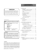
CONTENTS 1. INTRODUCTION ........................................................... 1-2 CAUTION 1.1 Features .............................................................. 1-2 1.2 Internal Preset Memory Capability .................. 1-3 The power cord provided with this monitor is designed for safety and must be used with a properly grounded outlet to avoid possible electrical shock. 1.3 Power Management Function ..........................
1 INTRODUCTION Congratulations on your purchase of the high resolution color monitor. We designed this monitor to provide you with years of reliable trouble-free operation. This guide tells you how to connect, adjust and care for your monitor. This guide also provides technical specifications and instructions for troubleshooting any basic problems you may experience with your monitor. 1.
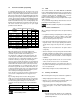
1.2 Internal Preset Memory Capability 1.4 To minimize adjustment needs, the factory has preset popular display standards into the monitor, as shown in Table 1. If any of these display standards are detected, the picture size and position are automatically adjusted. All of the factory presets may be overwritten by adjusting the user controls. This monitor is capable of automatically storing up to 15 additional display standards.
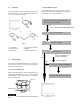
1.7 1.9 Quick Operation Chart Unpacking After you unpack the box you should have all of the items indicated in Figure 1. Save the box and packing materials in case you transport the monitor. 1 To summarize the steps in connecting your computer with the color monitor and setting the necessary controls and switches, refer to the chart below. 2 Connect the color monitor and computer with the necessary cords and cables. See Section 3. INSTALLATION AND CONNECTION 4 3 5 Turn on the color monitor.
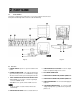
2 PART NAME 2.1 Control Names See Figures 3 and 4 for the location of the user controls, indicator and connectors. Each part is identified by number and is described individually. Figure 4 Figure 3 2.2 Function 1. POWER SWITCH: A push-on / push-off switch for AC power. 5. FUNCTION ADJUST BUTTONS: Push the adjust buttons to adjust the image on the screen. 2.
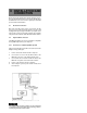
3 INSTALLATION AND CONNECTION On the back of the monitor three kinds of plug-in connections are provided: AC power connector for the AC input, two DB9-15P connectors for video signal input, and USB ports for USB communication. 3.1 AC Power Connection One end of the AC power cord is connected to the AC power connector on the back of the monitor. The other end is plugged into a properly grounded three-prong AC outlet.
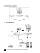
3.2.2 Connecting to Two Computers Figure 6 shows the connection to two computers. Refer to clause 3.2.1 for the connection procedure. Figure 6 3.3 USB System Basic Application The Computer is required to have Windows® 98 or later installed and USB functions.
3.4 Installation of USB Function The following procedure permits your computer to recognize or "enumerate"(A USB term) the USB HUB. 1. Power on the display monitor and then the computer. 2. Start "Enumeration" from the Windows® Desktop. • During the enumeration of USB Hub, connect the keyboard and mouse, to the computer and not to the downstream ports on the display monitor. After the enumeration, the keyboard and mouse can be used by connecting to the downstream ports, if they are USB-compliant.
4 OSD (On Screen Display) FUNCTIONS 4.1 How to adjust the screen The monitor has an OSD(On Screen Display) function. The following procedure shows how to adjust the screen using the OSD function. If you don't press any button for the time set at "OSD TURN OFF", the OSD will turn off automatically.
4.2 Adjustment Items A. Press "FACTORY PRESET" to restore to the factory preset level. B. Press - and + buttons together, to restore to the factory preset level. C. Set data does not change by the change of the signal timing.
X: Available If a non-Factory Preset timing is used, "FACTORY PRESET" does not work.
5 TROUBLESHOOTING PROBLEM Before calling your Authorized Product Support, please check that the items below are properly connected or set. In case of using a non-standard signal, please check the pin assignments and the signal timing of your computer with the specification outlined in Section 6. SPECIFICATIONS and Section 7. APPENDIX. LOCATION ITEMS TO CHECK • Contrast and brightness controls. • Front • Power switch. • AC power cord disconnected. • Front • Rear • Signal cable disconnected.
PROBLEM Abnormal Picture Black vertical lines are visible on the screen. Thin vertical black lines on one or both sides of the screen. This minor condition is caused by grille element overlap which can occur during shipping. Position an open white window over the affected area of the screen and maximize the brightness and contrast controls. This will cause localized heating of the overlap which will clear in a few minutes.
6 SPECIFICATIONS CRT INPUT SIGNAL SIGNAL INTERFACE USB Size 55cm/22" (508mm/20" Viewable Image Size) Mask type Aperture grille Gun In-line Deflection angle 90° Phosphors Red, Green, Blue EBU (medium short persistence) Aperture grille pitch 0.24mm Phosphor pitch 0.25mm Face Plate G-WARAS Focusing method Dynamic Beam Forming (DBF) Video 0.7Vp-p analog RGB Sync Separate H, V sync., Composite sync., or Sync on Green Input Connectors DB9-15P X 2 Input Impedance 75 Ohms(video), 2.
7 7.1 APPENDIX Monitor Signal Input Connector (DB9-15P) (Female) 7.2 Signal Cable Approx. 1.8m DB9-15P MOUNTED ON THE REAR PANEL PIN ASSIGNMENTS Pin No. 1 2 3 4 5 6 7 8 9 10 11 12 13 14 15 Signal RED VIDEO GREEN VIDEO BLUE VIDEO GROUND DDC GROUND RED GROUND GREEN GROUND BLUE GROUND *+5 V(FROM HOST COMPUTER) SYNC GROUND GROUND SDA HORIZONTAL SYNC or COMPOSITE SYNC VERTICAL SYNC(VCLK) SCL DDC ...................DISPLAY DATA CHANNEL SDA ...................SERIAL DATA SCL ...................